UNIT 5
Internal Combustion Engines
Internal combustion (IC) engines- the fuel used undergoes combustion inside the engine in the presence of air. The product produced by the combustion becomes the working fluid of the engine.
Internal combustion engines have higher efficiency and are lighter in weight in comparison to the power developed. They have become very much suitable for mobile applications. With all these advantages, IC engines have become universal means of power generation and very much popular.
Classification of Internal Combustion (IC) Engine:
Internal combustion engines may be classified based on:
- Thermodynamic cycle used – Otto cycle, diesel cycle, and dual cycle engine
- Fuel used – Petrol engine, diesel engine, gas engine, and kerosene oil engine
- Number of strokes for completion of the cycle – Four-stroke engine and two-stroke engine
- Types of fuel ignition – Spark ignition (SI) and compression ignition (CI)
- Number of cylinders – Single cylinder engine and multi-cylinder engine
- Position of cylinders – Horizontal, vertical, V-engine, and radial engine
- Method of cooling engines – Air-cooled engine and water-cooled engine
Components of Internal Combustion (IC) Engine:
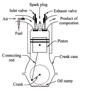
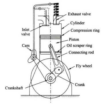
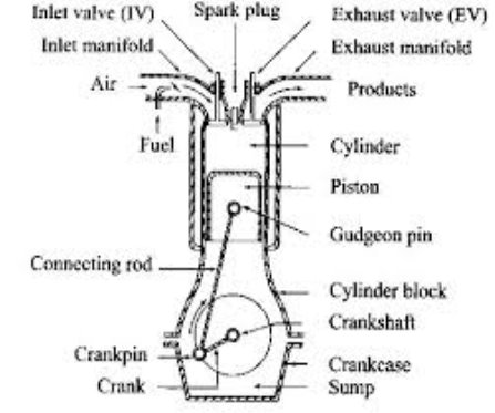
An assembled diagram with various parts of an IC engine is shown in Figure
i. Engine Cylinder:
It is a cylindrical vessel in which the fuel is burnt and the product of combustion gets expanded to develop power. Inside the cylinder, there is a sleeve fitted called the cylinder liner of hard metal. A piston makes a reciprocating motion inside the cylinder.
Ii. Cylinder Head:
It is fitted at the top of the cylinder to cover the cylinder. The cover provides the accommodation of the inlet valve, exhaust valve, and spark plug (in SI engine) or injector (in CI engine).
Iii. Piston:
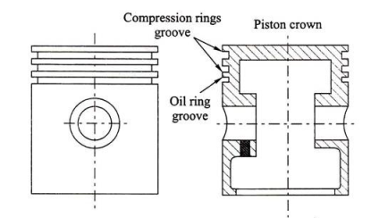
The piston is a tightly fitted block generally known as a trunk piston which receives the gas pressure inside the engine cylinder. The gas pressure is transmitted to the crankshaft through the connecting rod (Fig. 4.27).
Piston Rings:
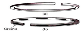
There are two types of rings fitted on the circumferential groove provided on the outer surface of the piston (Fig. 4.28):
Compression Ring:
Compression rings maintain a gas-tight contact between the cylinder and the piston.
Oil Scraper Ring:
Lubrication is required in the cylinder sleeve surface to reduce frictional forces. However, the excess oil needs to be removed. Thus, the ring will have a groove that removes this excess lubricating oil from the sleeve of the cylinder into the crankcase.
Connecting Rod:
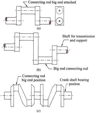
The connecting rod transmits the force from the piston to the crankshaft. It helps in converting the reciprocating motion to rotary motion. It has two ends—a small end and a big end. The small end is connected with a piston with a gudgeon pin. The big end is connected with the crankshaft (Fig. 4.29).

Crank and Crankshaft:
It converts the reciprocating motion of the piston to the rotary motion of the shaft. The crankshaft is enclosed inside a crankcase [Figs. 4.30(a) – 4.30(c)].
Valves:
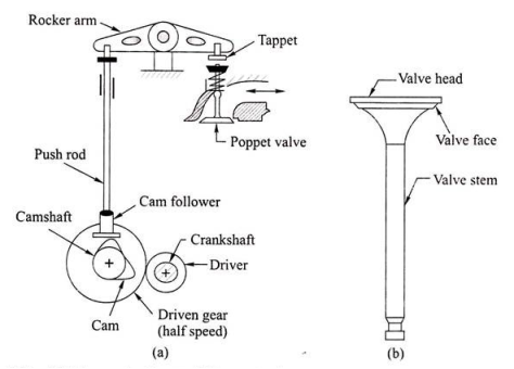
These valves are also called poppet valves.
There are two types of valves:
i. Suction valve and
Ii. Exhaust valve.
i. Suction Valve:
This valve controls the mixture of petrol vapors and air in SI engines and only air in CI engines.
Ii. Exhaust Valve:
It controls the flow of exhaust gas from the cylinder. The product of combustion is to be expelled out by opening this valve for starting a fresh cycle.
The valves are operated by a cam mechanism with the help of rocker arms in a single-cylinder engine and by camshaft in a multi-cylinder engine [Figs. 4.31(a) and 4.31(b)]. In four-stroke engines, the rotation of the camshaft is half of the rotation of the crankshaft.
FlyWheel:
The flywheel is a heavy wheel mounted on the engine shaft. It has a large moment of inertia and, hence, absorbs energy during operation and supplies back the energy to the engine when required. Thus, this removes the cyclic fluctuation and maintains uniform rotation of the crankshaft. A single-cylinder engine will have a large flywheel, whereas a multi-cylinder engine will have a smaller flywheel.
Crank Case:
It is fitted in the lower part of the engine cylinder to cover the crankshaft and also to store the lubricating oil known as oil sump.
In a two-stroke engine, the working cycle is completed in two-stroke of the piston or one revolution of the crankshaft. This is achieved by carried out suction and compression in one stroke expansion and exhaust in the second stroke.
A two-stroke engine has a port instead of valves. The opening and closing of the port are controlled by the piston
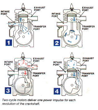
Following are the process in a two-stroke engine
1) Suction stroke: In this stroke piston while moving downward BDC (bottom dead centre) both the transfer port and exhaust port are open. The fresh fuel-air mixture flows into the engine cylinder from the crankcase.
2) Compression stroke: In this stroke, the piston while moving upwards, first covers the transfer port then exhausts the port. After that fuel is compressed as the piston moves upwards. In this stage, the inlet port opens and the fresh air-fuel mixture enters into the crankcase.
3) Expansion stroke: During the compression stroke the piston reached TDC (top dead centre) the charge is ignited with the help of a spark plug. It suddenly increases the pressure and temperature of the product of combustion and volume remain constant. Due to the rise in pressure, the piston is pushed downwards with greater pressure. During the expansion, some of the heat energy is produced and transformed into mechanical work.
4) Exhaust stroke: In this stroke, the piston moves downward and the exhaust port is opened. The burned gases are exhaust from the engine cylinder through the exhaust port into the atmosphere.
The two-stroke engines lighter, simpler, and less expensive to manufacture. Two-stroke engines also have the potential to pack about twice the power into the same space because there are twice as many power strokes per revolution. The combination of lightweight and twice the power gives two-stroke engines a great power-to-weight ratio compared to many four-stroke engine designs.
Four-stroke engine
In the four-stroke engine, the working cycle is completed in four-stroke of the piston or two revolutions of the crankshaft. This is achieved by carried out suction in one stroke and compression in the second stroke, expansion in the third stroke, and exhaust in the fourth stroke. They have an inlet and exhaust valve. Suction and compression in one revolution of crankshaft, expansion, and exhaust in the second revolution of the crankshaft.
Following is the process in the four-stroke engine;
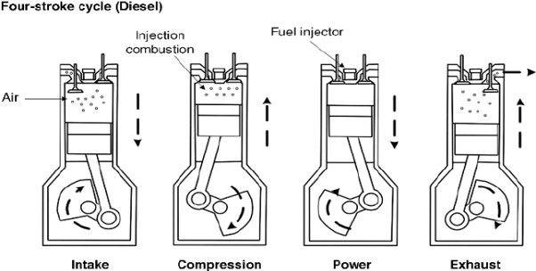
1) Suction stroke: In this stroke, while the piston moving downward BDC (bottom dead centre) inlet valve opens, and pure air is sucked into the cylinder.
2) Compression stroke: In this stroke, the piston while moving from BDC to TDC, the inlet and outlet valve are closed. The compressed start as the piston moves upwards. Which increase pressure and temperature .this complete one revolution of the crankshaft
3) Expansion stroke: just before the piston reached the top dead centre fuel oil was injected in the form of very fine spray into the cylinder. At this point temperature of the compressed air is sufficiently high to ignite the fuel which suddenly increases the pressure and temperature of combustion products. Due to an increase in pressure, the piston is pushed down with a great force.
4) Exhaust stroke: In this stroke exhaust valve opens as the piston move from BDC to TDC. This movement of the piston moves up and pushed out the burned gases to the atmosphere from the engine cylinder
SI and CI engine
S.I Engine:
S I Stands for Spark Ignition. This is one kind of IC (Internal Combustion) engine.
There are four processes in the engine.
- Intake or suction
- Compression
- Power or combustion
- Exhaust


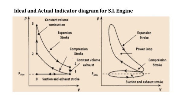
Process 0-1 (Suction stroke)
At the start of the cycle, the piston moves from TDC to BDC. The inlet valve (I.V.) is opened automatically by the valve operating mechanism at the start of this process. Due to the increase in volume inside the cylinder, a slight vacuum is created and, the fresh charge i.e. a mixture of air and petrol prepared in Carburettor is sucked inside the cylinder through the inlet valve. At the end of the stroke, the piston reaches BDC position, the total volume of a cylinder is filled with fresh charge and the inlet valve is closed. Theoretically, the charge is filled at constant pressure P1 and it occupies the total volume of cylinder V1.
Process 1-2 (Compression stroke)
During this stroke, both the valves remain closed and the piston is moved from BDC to TDC by the force of the crank. As the piston moves up, the volume of the cylinder shrinks, and the fresh charge is compressed to a higher pressure P2 and volume V2 equal to clearance volume. Theoretically, this process is an adiabatic compression process. The temperature of fresh charge is also raised in compression from T1 to T2.
Process 2-3 (heat addition or constant volume combustion)
This process is a constant volume heat addition process. At point 2, the spark plug ignites and starts the combustion of an already compressed, high-temperature charge. Due to very favourable conditions of combustion, combustion of charge and heat release takes place in no time and pressure & temperature further shoots up to P3 and T3. Theoretically, the volume remains constant from 2 to 3. So V2=V3=VC=Clearance Volume.
Process 3-4 (expansion or working stroke)
This is the process or stroke of the piston in which positive work is obtained. The burnt gases at high pressure and high temperature at point 3 expand and push the piston again from TDC to BDC, thus doing work on the piston. This work is given to the output shaft of the engine through the connecting rod and crankshaft. A small portion of it is stored in the heavy rotating flywheel mounted on the crankshaft, which is used in the movement of the piston in three other idle strokes i.e. Suction, Compression, and Exhaust. When the piston reaches BDC, the cylindrical total volume is filled with comparatively lower pressure and temperature burnt gases or smoke. At this point 4, the exhaust valve (EV) opens.
Process 4-1 (heat rejection or constant volume exhaust)
In this process, as soon as the exhaust valve is opened at point 4, the burnt gases start escaping to the atmosphere and their pressure reduces to atmospheric pressure P1. Theoretically, this process happens in no time, and escaping exhaust gases takes away some heat from the engine.
Process 1-0 (exhaust stroke)
This stroke is just the opposite of a suction stroke. The piston moves from BDC to TDC and pushes away or sweeps the remaining burnt gases out through E.V. As the piston reaches TDC most of the burnt gases escape and E.V. Is closed. One cycle of the engine completes here. Simultaneously, the I.V. Opens and the next cycle starts.
In this way, the piston goes on moving or reciprocating from TDC to BDC and BDC to TDC with a high speed and the engine produces power continuously by burning petrol or gas, etc. The power output and RPM of the engine can be easily controlled by a throttling valve fitted in the passage of air intake or in the carburetor where fuel and air are mixed together in the right proportion In the exhaust phase, the piston goes upward and the burnt gases go away through the exhaust valve.
C.I Engine:
A diesel engine is called a compression Ignition engine because here the conditions of combustion or ignition are achieved only by compression of air to very high pressure.
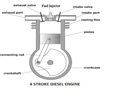
There is no spark plug to initiate the combustion, but in place of that, a fuel injector is there, which injects and atomizes the fuel. Diesel at very high pressure in very hot compressed air after compression stroke in engine Due to high pressure and temperature above the ignition temperature, fuel atomization, evaporation, and self-ignition take place.
The rest of the working of Diesel Engine is same as that of Petrol or Gasoline Engine. Here also one complete cycle is comprised of all the processes of Diesel cycle along with suction of fresh air and exhaust of burnt gases. To carry out all these processes, here also normally 4 strokes of the piston are required. So, it is called a 4-stroke Diesel Engine or C.I Engine.

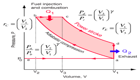
Process e-a (suction stroke)
At the start of the cycle, the piston moves from TDC to BDC, and the inlet valve is opened at the start of the process at point e. Due to the increase in the volume of a cylinder by the movement of the piston, the fresh air from the atmosphere enters the cylinder and occupies all the space inside the cylinder until the piston reaches BDC. At a point, an air-filled cylinder is at volume V1 and its pressure & temperature are theoretically the same as that of the outside atmosphere. Here inlet valve is closed and the cylinder becomes a closed thermodynamic system.
Process a-b (compression stroke)
In this stroke, the piston moves from BDC to TDC by the force of the crank. As both valves are closed, the air sucked in the previous stroke is compressed to the clearance volume. Here in Diesel engine, the compression ratio RC which is the ratio of total volume V1 to clearance volume V2 is very high as compared to SI Engine. So, naturally, the rise in pressure and temperature of the air at the end of the compression stroke is also more. The range of RC (compression ratio) in Diesel Engine is 15 to 22. Theoretically, the compression process is adiabatic & isentropic Compression.
Process b-c (heat addition or fuel injector)
This process is actually a constant pressure heat addition process or a mix of constant volume and constant pressure process as in the case of a high-speed diesel engine. At point b the fuel injector injects a fixed quantity of fuel in very hot & compressed air compressed to the clearance volume. Due to that fuel spray ignites itself thus releasing heat in the cylinder. As this heat addition process is slow, the piston moves back to some distance from TDC to point c shown in fig, and the volume increases which nullifies the effect of an increase in pressure due to heat addition. Pressure remains constant theoretically up to point c, where the injector stops injection of fuel and so the addition of heat. Point c is also called the cut-off point. A part of piston stroke from b to c takes place along with this process and the burning fuel plus air mixture expand and pushes the piston producing a positive work.
Process c-d (expansion stroke or power stroke)
Actually the complete expansion stroke is from point b to point d but a part of it is along the previous heat addition process b-c. After point c heat addition stops and the hot and high pressure burnt gases expand at the cost of their own internal energy and produce positive work by pushing the piston to BDC. This stroke is called a working stroke as here piston moves the crankshaft and gives mechanical energy. The major part of this energy is given to the output shaft and a small portion is stored in the heavy flywheel in the form of its rotational kinetic energy and used up during idle strokes of piston i.e. Suction, Compression & Exhaust.
Process d-a (heat rejection)
This process takes place at constant volume and heat is rejected directly by escaping some of the burnt gases due to pressure difference inside and outside the engine as soon as the exhaust valve opens at point d i.e. just at the end of expansion or working stroke. Theoretically, the piston remains at BDC and gases escape in no time, taking away some heat from the engine. The pressure inside the cylinder reduces to atmospheric pressure.
Process a-e (exhaust stroke)
In this process or stroke, the piston is moved by a crank from BDC to TDC. As the exhaust valve remains open during this stroke, the piston displaces or sweeps out the burnt gases through it and only a small fraction of gases remain in the clearance volume finally. The piston reaches TDC and the cycle completes as the initial conditions are again reached. At this point, the exhaust valve closes and inlet valve opens and the next cycle starts.
In this way, the piston moves or reciprocates from TDC to BDC and again from BDC to TDC with a high speed and the engine produces power continuously by burning of air and fuel mixture. The power output and RPM of the engine here can be controlled by controlling the quantity of fuel injected only. There is no restriction on the quantity of air sucked by the engine. There is a mechanical or electric control on the fuel injection depending on the fuel injection system used. When more power is required more quantity of fuel is injected and when less power is required accordingly fuel supply is reduced. There is no control on the quantity of air so air sucked remains more or less the same. In this way, only the quality of combustible mixture changes in different conditions of loading and so Quality Governing is used in CI Engine.
OTTO CYCLE: Otto cycle is a thermodynamic cycle upon which a spark-ignition engine works. Spark Ignition (or SI) engine uses petrol (or Gasoline) as fuel. The Otto cycle was invented by Nicolas Otto in 1876.
Spark ignition engine is a type of internal combustion engine.
Below are P-V and T-S Diagrams of the Otto Cycle.
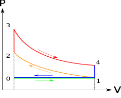
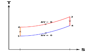
Otto Cycle is comprised of four processes (apart from the intake and exhaust process)
Process 1-2: This process comes after the intake process. In the case of SI engines, intake is a mixture of gasoline and air, also known as a charge. In this process, the charge is compressed in an isentropic manner. Temperature raised from T1 to T2 and volume decrease from V1 to V2.
Process 2-3: In this process, the fuel gets blasted with the help of an external spark (that is why the engine is known as a spark-ignition engine). This process is a constant volume heat addition process. Temperature raised from T2 to T3
.
Q2-3= CV(T3-T2)
Process 3-4: After the combustion process, the exhaust gases expand. This process is an isentropic expansion process. No heat is interchanged. The temperature falls from T3 to T4 and volume increase from V3 to V4.
Process 4-1: After the expansion process, the exhaust valve opens. This results in a sudden drop of pressure inside the engine cylinder. This process is a constant volume heat rejection process.
Q4-1= CV(T4-T1)
Process 0-1 is the intake process and process 1-0 is the exhaust process.
The efficiency of the Otto Cycle is the ratio of work output to the heat input.
Work done or output = Heat supply-Heat rejected
Work output = [CV (T3-T2)] – [CV (T4-T1)]
Heat Input = CV (T3-T2)
Efficiency = Work done / Heat Input
After putting values of heat input and work output in the above formula, we get
η = [CV (T3-T2)] – [CV (T4-T1)] / CV (T3-T2)
η = 1 – [(T4-T1)/ (T3-T2)]
η = 1 – [T1 (T4 / T1 – 1 )/ T2 (T3/T2 - 1)]
r = compression ratio = V1 / V2 = V4 / V3
T2 = T1 (V1/V2) y-1
T2 = T1 (r) y-1 …..equation 1
T3/T4 = (V4 /V3)y-1
T3 = T4 (r) y-1 ……equation 2
From equation 1 and 2
T2 / T1 = T3/T4
Or T4 / T1 = T3 / T2
Put the value in this equation
η = 1 – [T1 (T4 / T1 – 1)/ T2 (T3/T2 - 1)]
We get
η = 1 – [T1 / T2]
Or η = 1 – 1 / (r )y-1
DIESEL CYCLE
Diesel cycle is a gas power cycle invented by Rudolph Diesel in the year 1897. It is widely used in diesel engines.
The diesel cycle is similar to the Otto cycle except in the fact that it has one constant pressure process instead of a constant volume process (in the Otto cycle).
The diesel cycle can be understood well if you refer to its p-V and T-s diagrams.
P-V and T-s Diagrams of Diesel Cycle:
p-V Diagram |
T-s Diagram |
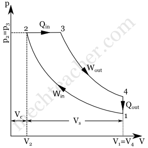 | 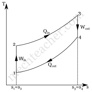 |
Processes in Diesel Cycle:
The diesel cycle has four processes. They are:
- Process 1-2: Isentropic (Reversible adiabatic) Compression
- Process 2-3: Constant Pressure (Isobaric) Heat Addition
- Process 3-4: Isentropic Expansion
- Process 4-1: Constant Volume (Isochoric) Heat Rejection
Process 1-2: Isentropic Compression
In this process, the piston moves from the Bottom Dead Centre (BDC) to Top Dead Centre (TDC) position. Air is compressed isentropically inside the cylinder. The pressure of air increases from p1 to p2, temperature increases from T1 to T2, and volume decreases from V1 to V2. Entropy remains constant (i.e., s1 = s2). Work is done on the system in this process (denoted by Win in the diagrams above).
Process 2-3: Constant Pressure Heat Addition
In this process, heat is added at constant pressure from an external heat source. Volume increases from V2 to V3, temperature increases from T2 to T3, and entropy increases from s2 to s3.
Heat added in process 2-3 is given by
Qin = mCP(T3 − T2) kJ ………… (i)
Where,
m → Mass of air in kg
Cp → Specific heat at constant pressure in kJ/kg K
T2 → Temperature at point 2 in K
T3 → Temperature at point 3 in K
Process 3-4: Isentropic Expansion
Here the compressed and heated air is expanded isentropically inside the cylinder. The piston is forced from TDC to BDC in the cylinder. The pressure of air decreases from p3 to p4, temperature decreases from T3 to T4, and volume increases from V3 to V4. Entropy remains constant (i.e., s3 = s4). Work is done by the system in this process (denoted by Wout in the p-V and T-s diagrams above).
Process 4-1: Constant Volume Heat Rejection
In this process, heat is rejected at constant volume (V4 = V1). Pressure decreases from P4 to P1, temperature decreases from T4 to T1 , and entropy decreases from s4 to s1.
Heat rejected in process 4-1 is given by
Qout = mCv(T4 − T1) kJ ………… (ii)
Where,
m → Mass of air in kg
Cv → Specific heat at constant volume in kJ/kgK
T2 → Temperature at point 2 in K
T3 → Temperature at point 3 in K
Air-standard Efficiency of Diesel Cycle:
Air-standard efficiency (or thermal efficiency) of diesel cycle is given by:
ηTh= ηDiesel= Heat Added – Heat Rejected / HeatAdded×100%
ηDiesel=Qin−Qout / Qin×100%
From equations (i) and (ii)
ηDiesel= mCp(T3–T2)– mCV(T4–T1) / mCp (T3–T2)×100%
ηDiesel = (1−mCV (T4−T1) / mCp(T3−T2))×100%
ηDiesel = (1−CV (T4−T1)/ Cp(T3−T2))×100%
ηDiesel = (1−1 / γ (T4−T1) / (T3−T2))×100% (Since Cp / CV= γ
CV / Cp=1/γ
References:
1. Engineering Thermodynamics, P K Nag, The Tata McGraw-Hill Companies
2. Mechanical Engineering Design, Joseph E Shigley, Charles R Mischke, The Tata McGraw-Hill Companies
3. Production Technology Vol. I & II, O.P. Khanna, Dhanpat Ray Publications