Unit 8
MANUFACTURING TECHNOLOGY
a) Center lathe:
i) Construction
Center or Engine Lathe Machine is the most widely used lathe machine and still, it is, in every workshop, this machine is present. An operation like Turning, facing, grooving, Knurling, threading, and more, such operations are performed on this type of machine.
The Center lathe machine has all the parts such as bed, Saddle, headstock, and tailstock, etc. The headstock of an engine lathe is rigid and the tailstock is moveable which is further used to support an operation like knurling. It can easily feed the cutting tool in both directions i.e. longitudinal and lateral directions with the help of feed mechanisms. Center Lathe machines are driven by the gear mechanism or pulley mechanism. It has three types of driven mechanisms, and those are Belt-driven, Motor-driven, gear head type.
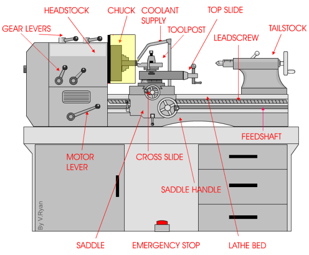
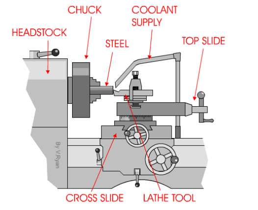
The Center Lathe is used to manufacture cylindrical shapes from a range of materials including; steels and plastics. Many of the components that go together to make an engine work have been manufactured using lathes. These may be lathes operated directly by people (manual lathes) or computer-controlled lathes (CNC machines) that have been programmed to carry out a particular task. A basic manual center lathe is shown below. This type of lathe is controlled by a person turning the various handles on the top slide and cross slide to make a product/part.
The headstock of a center lathe can be opened, revealing an arrangement of gears. These gears are sometimes replaced to alter the speed of rotation of the chuck. The lathe must be switched off before opening, although the motor should automatically cut off if the door is opened while the machine is running (a safety feature).
The speed of rotation of the chuck is usually set by using the gear levers. These are usually on top of the headstock or along the front and allow for a wide range of speeds.
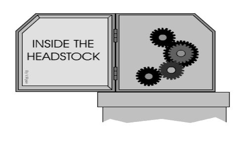
However, sometimes the only way to set the lathe to a particular speed is to change the gear arrangement inside the headstock. Most machines will have some alternative gear wheels for this purpose.
Ii) Basic element:
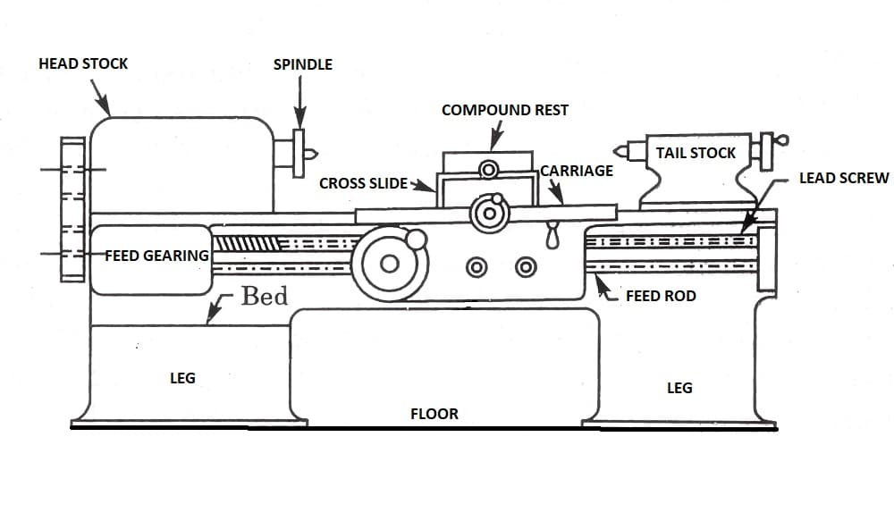
A lathe machine tool consists of several parts like:
- Headstock
- Bed
- Tailstock
- Carriage
- Saddle
- Cross-slide
- Compound rest
- Toolpost
- Apron
- Lead Screw
- Feed rod
- Chuck
- Main spindle
- Leg
1) Head Stock:
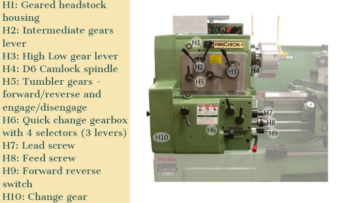
Head Stock is situated on the left side of the lathe bed and it is the house of the driving mechanism and electrical mechanism of a Lathe machine tool.
- It holds the job on its spindle nose having external screw threads and internally Morse taper for holding lathe center. And it is rotating at a different speed by cone pulley or all geared drive. There is a hole throughout the spindle for handling long bar work.
- Head Stock transmits power from the spindle to the feed rod, lead screw, and thread cutting mechanism.
Accessories mounted on headstock spindle:
- Three jaw chuck
- Four jaw chuck
- Lathe center and lathe dog
- Collect chuck
- Faceplate
- Magnetic chuck
A separate speed change gearbox is placed below the headstock to reduce the speed to have different feed rates for threading and automatic lateral movement of the carriage. The feed rod is used for most turning operations and the lead screw is used for thread cutting operation.
2) Bed:
It is the base of the lathe machine. It is made of single piece casting of Semi-steel (Chilled Cast Iron). The bed consists of two heavy metal slides running lengthwise, with ways or ‘V’ formed upon them and rigidly supported with cross girths.
- It is sufficiently rigid and good damping capacity to absorb vibration.
- It prevents the deflection produced by the cutting forces.
- It supports the headstock, tailstock, carriage, and other components of the lathe machine.
3) Tail Stock:
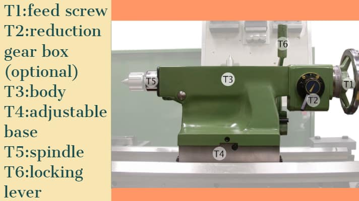
Tail Stock is situated on the right side above the lathe bed. It is used for:
- Support the long end of the job for holding and minimizes its sagging.
- It holds the tool for performing different operations like drilling, reaming, tapping, etc.
- And it is also used for a small amount of taper for a long job by offsetting the tailstock.
4) Carriage:
The carriage is used to support, guide, and feed the tool against the job when the machining is done.
- It holds moves and controls the cutting tool.
- It gives rigid supports to the tool during operations.
- It transfers power from feed rod to cutting tool through an apron mechanism for longitudinal cross-feeding.
- It simplifies the thread cutting operation with the help of a lead screw and half nut mechanism.
It is consists of:
- Saddle
- Cross-slide
- Compound rest
- Toolpost
- Apron
It provides three movements to the tool:
- Longitudinal feed-through carriage movement
- Cross feed-through cross slide movement
- Angular feed-through top slide movement
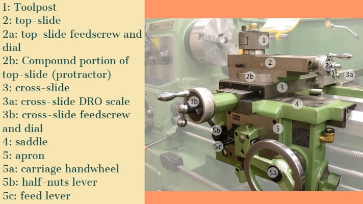
5) Saddle:
Generally, it is made up of ‘H’ shaped casting and it has a ‘V’ guide and a flat guide for mounting it on the lathe bed guideways.
6) Cross-slide:
It is assembled on the top of the saddle. The top surface of the cross-slide is provided with T-slot.
7) Compound rest:
It supports the tool post and cutting tool in its various positions. It can be swiveled at any desired position in the horizontal plane. It is necessary for turning angles and boring short tapers.
8) Tool post:
It is the topmost portion of the carriage and it is used to hold various cutting tools or tool holders. There are three types of tool post commonly used and those are:
- Ring and rocker tool post
- Squarehead tool post
- Quick change tool post
9) Apron:
An apron is a house of the feed mechanism. It is fastened to the saddle and hangover in front of the bed.
10) Lead screw:
A lead screw is also known as a power screw or a translation screw. It converts rotational motion to linear motion. Lead Screw is used for Thread Cutting operation in a lathe machine tool.
11) Feed Rod:
Feed rod is used to move the carriage from the left side to the right side and also from the right side to the left side.
12) Chuck:
Chuck is used to holding the workpiece securely.
There are generally 2 types of chucks:
- 3 jaw self-cantering chuck
- 4 jaw independent chuck
13) Main Spindle:
The spindle is a hollow cylindrical shaft in which long jobs can pass through it.
It is designed so well that the thrust of the cutting tool does not deflect the spindle.
14) Leg:
Legs are carrying an entire load of a lathe machine tool and transfer to the ground. The legs are firmly secured to the floor by the foundation bolt.
Iii) Working operation on the lathe:
A Lathe Machine consists of the following operation:
1) Centering
2) Facing
3) Turning
4) Chamfering
5) Knurling
6) Thread cutting
7) Drilling
8) Boring
9) Reaming
10) Spinning
11) Tapping
12) Parting off
Before continuing any operation in lathe we have to load the job and center it on the head-stock spindle.
In lathe operations, the headstock spindle holds the job and it rotates with the same speed as the spindle. The carriage holding the tool on the tool post, also the carriage gives the tool post moves longitudinally or crosswise direction to give the desired feed on the job.
These two motions (longitudinally and crosswise) help to remove the chips of the metal and giving the proper shape of the job. The Lathe is such a versatile machine that it can produce another lathe. It is tough to mention which operations are not performed in a lathe machine tool, though we discuss some important lathe operations in detail.
1) Centering operation in the lathe:
We use this operation for producing a conical hole in the face of the job to make the bearing support of the lathe center when the job is to hold between two canters. (Head-stock and Tail-stock)
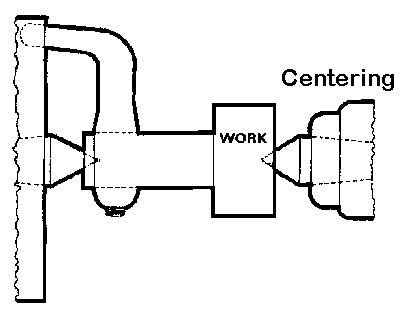 CENTERING OPERATION
2) Facing operation in the lathe:
Facing operation is for making the ends of the job to produce a smooth flat surface with the axis of operation or a certain length of a job. In this operation,
- Hold the job on the Head-stock spindle using a Three or four-jaw chuck.
- Start the machine on the desire RPM to rotate the job.
- Give a desirable feed on the perpendicular direction of the axis of the job.
![22 Types of Lathe Machine Operations [Complete Guide] PDF](https://glossaread-contain.s3.ap-south-1.amazonaws.com/epub/1642991405_7347958.jpeg)
3) Turning operation in the lathe:
The operation by which we remove the excess material from the workpiece to produce a cone-shaped or a cylindrical surface
There are several types of turning operations, those are:
- Straight turning
- Shoulder turning
- Rough turning
- Finish turning
- Taper turning
- Eccentric turning
Straight turning:
This operation is done to produce a cylindrical surface by removing excess material from the workpiece.
It is done in the following ways:
- Mount the job by suitable job holding device and check the trueness of the job axis with the lathe axis.
- Hold the cutting tool on the tool post and set the cutting edge at the job axis or slightly above it.
- Set the spindle as per the desired feed.
- Give depth of cut as per finish or rough cut.
- Start the machining.
- Engage automatic feed to move the carriage with the tool to the desired length, then disengage the feed, and the carriage is brought back to its starting.
- The process is repeated until the job is finished.
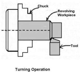
STRAIGHT TURNING OPERATION
Shoulder turning:
A shoulder turning is called which has a different diameter to form a step from one diameter to another. There are four kinds of shoulder.
- Square
- Beveled
- Radius
- Undercut
![22 Types of Lathe Machine Operations [Complete Guide] PDF](https://glossaread-contain.s3.ap-south-1.amazonaws.com/epub/1642991405_8905172.jpeg)
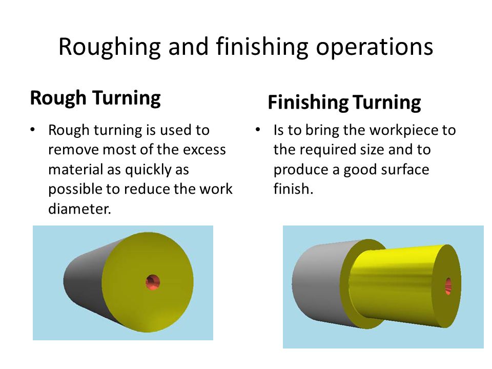
Rough turning:
It is a process of removal of excess material from the workpiece in minimum time by applying a high rate of feed and heavy depth of cut. The depth of cut is around 2 to 5mm and the rate of feed is 0.3 to 1.5mm/revolution.
Finish turning:
The finish turning operation needs high cutting speed, minimum feed, and a very small depth of cut to generate a smooth surface.
In finish turning the depth of cut is around 0.5 to 1mm and the rate of feed is 0.1 to 0.3 mm/revolution.
Taper turning:
A taper is defined as a uniform decrease or increase in the diameter of a workpiece along with its length.
The operation by which a conical surface of the gradual reduction in diameter from a cylindrical workpiece is produced is called taper turning.
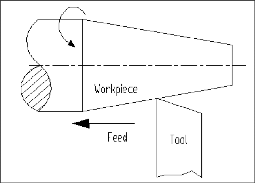
Taper turning methods:
A tapering form may be done by any one of the following methods.
- Taper turning by form tool
- By swiveling the compound rest
- Tail-stock set over method
- By taper turning attachment
Let me discuss them in brief.
Taper turning by form tool:
It is used to form a short length of taper by using a form tool or broad nose tool.
Any increase in the length of the taper will require the use of a wider cutting edge which may destroy the workpiece due to the vibration and spoil the workpiece. In this operation, the tool angle must be half of the taper angle.
Taper turning by swiveling the compound rest:
This method is used for turning step and short tapers.
It is done as follows:
- Set the compound rest by swiveling it from the centerline of the lathe center through an angle equal to a half taper angle.
- Clamp the carriage in place.
- After adjusting and setting the tool, feed is applied by the compound rest’s feed handle to complete the taper.
Tail-stock set over method:
Set over of tail-stock from its center-line is done equal to half taper.
Job is held between the centers. The length of the workpiece will be long enough. An only a small taper on a long job is done by this process.
It is used for external taper only.
By taper turning attachment:
It is done in the following ways:
- The cross slide is first made free from lead screw by hinder screw.
- The rear end of the cross slide is then tightened with a guide block by a belt.
- Set the guide bar at an angle to the lathe axis. (Half taper angle)
- The required depth of cut is given by the compound slide is at a right angle to the lathe axis.
4) Chamfering operation:
Chamfering is used for bevelling the end of a job to remove burrs, to look better, to make a passage of the nut into the bolt. This operation is done after thread cutting, knurling, rough turning.
![22 Types of Lathe Machine Operations [Complete Guide] PDF](https://glossaread-contain.s3.ap-south-1.amazonaws.com/epub/1642991406_1099536.jpeg)
5) Knurling operation:
It is the process of producing a rough surface on the workpiece to provide effective gripping. The knurling tool is held rigidly on the tool post and pressed against the rotating job so that leaving the exact facsimile of the tool on the surface of the job.
![22 Types of Lathe Machine Operations [Complete Guide] PDF](https://glossaread-contain.s3.ap-south-1.amazonaws.com/epub/1642991406_1622481.jpeg)
6) Thread cutting operation:
It is the operation that is used to produce a helical groove on a cylindrical or conical surface by feeding the tool longitudinally when the job revolved between the two canters.
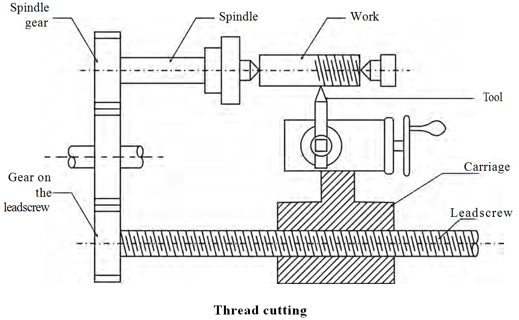
Tool setting for thread cutting operation:
The tool should be set exactly to the height of the centerline of the job and at 90 degrees to the job.
Tool setting gauge is used for this purpose.
Feeding during thread cutting operation:
It is done in two ways.
- The tool may be feed exactly at 90 degrees to the job axis but it does not have good cutting action because only the front end of the tool does cutting.
- The tool may be beefed at an angle from 27-30 degrees at which the compound rest may be set so that the complete side of the tool is used for cutting action which gives a better polish on the threads.
Job speed during threading:
The job speed will be 1/3 to 1/4th of the job speed in the turning operation.
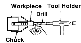
7) Drilling operation:
Drilling is an operation by which we can make holes in a job.
In this operation, the job is rotated at the turning speed on the lathe axis and the drilling tool is fitted on the tail-stock spindle. And the tail-stock is moved towards the job by hand feed.
8) Boring operation:
In this operation, we can enlarge the diameter of the existing hole on a job by turning inside with some farm tool known as a boring tool. The boring tool is also fitted on tail-stock.
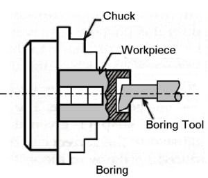
9) Reaming operation:
Reaming is the operation for sizing or finishing a drilled hole to the required size by a tool called a reamer. This tool is fitted on tail-stock.
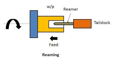
10) Spinning operation:
In this operation, the job of this sheet metal is held between the former and the tail-stock center rotates at high speed with the former. The long round nose forming tool rigidly fixed on a special tool post presses the job on the periphery of the former. So the job is taken exactly the shape of the former. This is a chipless machining process.
11) Tapping operation:
We use this operation for creating internal threads within a hole through a tool called tap.
Three taps are generally used in an internal thread.
- Taper Tap
- Second Tap
- Plug Tap
12) Parting-off operation:
It is the operation of cutting off a bar type job after complete the machining process. In this operation a bar type job is held on a chuck, rotates at turning speed, a parting off tool is fed into the job slowly until the tool reaches the center of the job.
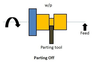
Iv) Turning and facing:
Turning:
Turning a taper on a long piece of material is best achieved by offsetting the tailstock. The material is held between two centers as a normal three-jaw chuck cannot be used. A three-jaw chuck will not hold the material safely or accurately when a long taper is being turned. Diagram ‘A’ below shows the side view of the two centers, the material, and the tool post. |
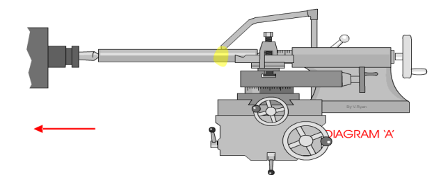 |
Diagram ‘B’ shows a bird’s eye view (plan view) of the same equipment. However, this time it can be seen that the tailstock has been adjusted so that it is off-center. This means that a long taper can be turned. A small amount of material must be removed with each pass of the cutting tool. Also, the lathe should be set up so that the cutting tool feeds automatically along the bed of the lathe. This will lead to a better finish to the surface of the material. The animation below shows a 'speeded up version' of taper turning. Normally taper turning takes a long time. |
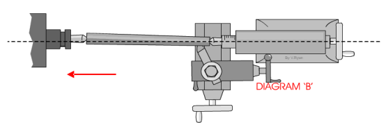 |
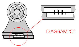
Diagram ‘C’ shows the scale at the back of the tailstock. To adjust the tailstock so that it is off-center usually means loosening some Allen screws, offsetting the tailstock, and then tightening the screws back in position.
Facing:
A very basic operation is called ‘facing off’. A piece of steel has been placed in the chuck and the lathe cutting tool is used to level the end. This is done by turning the cross-slide handle so that the cross-slide moves and the cutting tool cuts the surface of the steel. |
 |
Only a small amount of material should be removed - each pass of the cross slide. After each pass of the cutting tool, the top slide can be rotated clockwise to move the tool forward approximately 1mm.
This sequence is repeated until the steel has been leveled (faced off).
When using a center lathe it is always advisable to work patiently and safely. Do not attempt to remove too much material in one go. At best this will cause damage to the steel being worked on and to the expensive cutting tool being used. At worse an accident will occur.
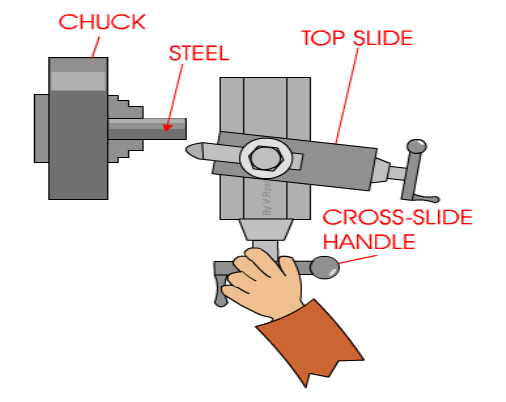
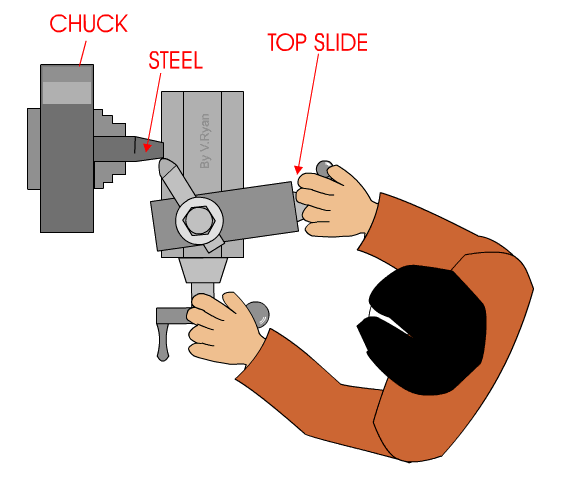
When turning a short taper the top slide is set a required angle. This is normally done by loosening two small Allen screws and then rotating the top slide to the angle and tightening back up the two Allen screws. |
 |
b) Drilling machine-
Drilling Machine is the simplest, moderate, and most accurate machine tool used in almost all production shops and tool rooms. Drilling is a single purpose machine tool as its main purpose is to make holes in the workpiece.
A machine consists of a spindle that provides rotary motion to the drilling tool, which finally makes the hole in the job(workpiece).
A drilling machine is a type of machine in which the holes are being made on the workpiece by making use of a rotating tool called drill bit or the twist drill. Drilling is a technology of creating holes.
Drilling operation can also be performed on Lathe Machine. In the lathe machine, the workpiece rotates and the drilling tool is held stationary in the tailstock.
Boring: When we talk about drilling, boring is mostly discussed.
Boring is a process in which the holes are enlarged that is already being drilled or cored. To perform boring action by a machine a special holder for the boring tool is required.
The basic element of a pillar drilling machine:
Vertical or Pillar Drilling Machine:
Vertical or Pillar Drilling Machine is free standing and is of a far heavier construction able to take larger drills.
It has a heavy frame to support a wider range of work.
The table height is adjustable and power speed and feeds are available.
The larger drills normally have a tapered shank located within the taper bore in the spindle end. These tapers are standardized as Morse tapers.
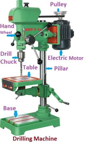
Various parts and their function of the drilling machine are:
1) Bed
2) Pillar
3) Swivel table
4) Motor
5) Steeped pulley
6) Spindle
7) Chuck
8) Drill Bit
9) Hand-wheel
10) Feed Mechanism
11)
1) Bed:
The bed is the main part of the machine on which the whole machine is being mounted. The bed is made up of cast iron, so it has high compressive strength and good wear resistance.
2) Pillar:
The pillar is a type of vertical column that rests on the bed. Pillar is present at the center of the bed. Pillar helps the motor and the spindle head.
3) Swivel Table:
The table is the place where the workpiece is being mounted. The table is attached to the column and it can be rotated around the column and can have an upward and downward moment. A table can be adjusted at any angle as per the requirement. The worktable is generally made of cast iron and it is mounted on the column. T-slots are provided at the top surface of the table may be in some table there is a vice which also helps to hold the job.
The table can move up and down as also right or left according to the job and tool arrangement. The up and down motion of the table can be given by hand as well as by some electrical mechanism. We use a rack and pinion mechanism for a vertical moment of the table.
The shape of the table can be rectangular or also circular.
4) Motor:
The motor is present at the top of the column. Inside the motor shaft is there which is connected to a stepped pulley so that we can increase or decrease the speed of the rotation of the motor.
5) Stepped pulley:
Two steeped pulleys are present on either side of the column at the top. Out of these two, one pulley will be in an upward direction while the other pulley is inverted. Always both the pulleys will be there in the opposite direction. The basic function of the stepped pulley is to control the speed of the rotation of the motor.
6) Spindle:
Spindle arrangement is present at top of the column opposite to the arrangement of the motor. The top of the spindle is attached to one of the stepped pulleys. The bottom of the spindle is connected to the chuck.
7) Chuck:
Chuck is present at the bottom of the spindle. The basic function of the chuck is to hold the cutting tool firmly.
8) Drill bit:
A drill bit is an actual cutting tool that is used to create a hole in the workpiece.
9) Hand Wheel:
The basic function of the handwheel is to adjust the spindle position as per the requirement.
10) Feed Mechanism:
In a drill machine, we use an electric motor, V-belt, and pulley to transfer the power from the motor to the spindle. For the up and down motion of the drill head, we use hand and as well as automatic feed by an electrical motor. Here also a rack and pinion are used to convert the rotational movement from an electrical motor or by hand to the straight-line movement.
Operation of Drilling Machine
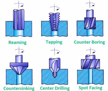
The various operations that can be performed in a drilling machine are:
1. Drilling
2. Boring
3. Reaming
4. Counter Boring
5. Counter Sinking
6. Spot Facing
7. Tapping
8. Lapping
9. Grinding
10. Trepanning
Operation of Drilling Machine
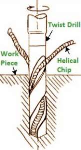
1. Drilling
- Drilling is an operation of producing a cylindrical hole by removing metal by rotating the edge of cutting tool call as Drill.
Drilling Operation
- This is one of the simplest methods of producing a hole.
- It doesn’t produce an accurate hole in a workpiece due to the vibration of the spindle and drill.
2. Boring
- The purpose of boring is to enlarge a hole through an adjustable cutting tool with only one cutting edge.
- It machines the internal surface of a hole already produced in casting.
- To correct out of roundness of the hole.
- To address the area of the gap as the drilling apparatus follows an autonomous way as for the gap.
3. Reaming
- It is a precise method for estimating and completing an opening that has been recently bored.
- The tool uses for reaming is known as the reamer which has multiple cutting edges.
- It can’t originate a hole.
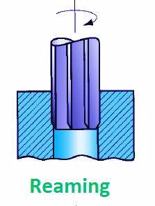
- It follows the way which has been recently bored and expels an extremely limited quantity of metal.
- The material removes through this process is around 0.375 mm and for accurate work, this should not exceed 0.125 mm.
4. Counter Boring
- This is an operation of enlarging the end of a hole cylindrically.
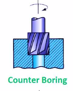
- The enlarged hole forms a square shoulder with the first gap.
- The cutting speed for this operation is 25 % less than that of drilling.
5. Counter Sinking
- It is an activity of making a cone-shaped enlargement of the end of a hole to provide a recess for a flat head screw or countersunk rivet fitted into the hole.
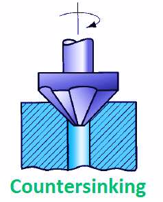
- The standard countersinks have 60°, 82°, or 90° included angle and the cutting edges of the tool are formed at the conical surface.
6. Spot Facing
- This is an operation of smoothing and squaring the surface around a hole for the seat for a nut or the head of a screw.
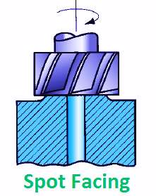
- A counterbore or an extraordinary spot confronting apparatus might be utilized for this reason.
7. Tapping
- This is an operation of cutting internal threads by means of a cutting tool called a tap.
- A tap might be considered as a jolt with precise strings cut on it.
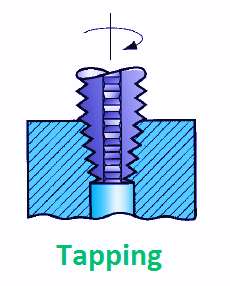
- The threads act as cutting edges which are solidified and ground.
- It removes metal and cuts internal threads which will fit into outer threads of the same size.
8. Lapping
- This is an operation of sizing and finishing a small diameter hole already hardened by removing a very small amount of material by using a lap.
- The lap fits in the hole and moves up and down while it revolves.
9. Grinding
- It is an operation to finish a hardened hole.
- The grinding wheel is made to rotate with the shaft and is exhausted and down.
- The accuracy in grinding operation is quite high about ± 0.1125 mm.
10. Trepanning
- This is an operation of producing a hole by removing metal along the circumference of a hollow cutting tool.
- It performs for producing large holes.

- The tool resembles a hollow tube having cutting edges at one end and a strong shank at the other to fit into the drill spindle.
- This is one of the effective strategies for delivering a hole.
c) Horizontal milling machine – construction and working
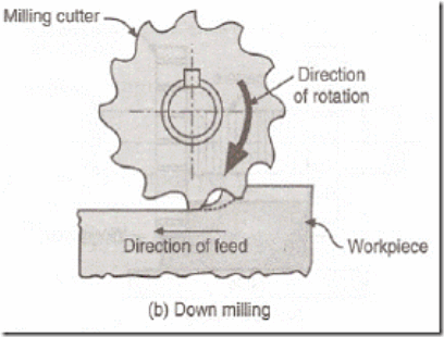
Milling is the cutting operation that removes metal by feeding the work against a rotating, cutter having single or multiple cutting edges. Flat or curved surfaces of many shapes can be machined by milling with good finish and accuracy. A milling machine may also be used for drilling, slotting, making a circular profile, and gear cutting by having suitable attachments.
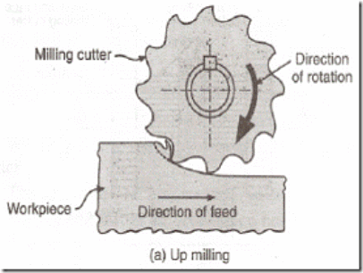
Working Principle: The workpiece is holding on to the worktable of the machine. The table movement controls the feed of the workpiece against the rotating cutter. The cutter is mounted on a spindle or arbor and revolves at high speed. Except for rotation the cutter has no other motion. As the workpiece advances, the cutter teeth remove the metal from the surface of the workpiece and the desired shape is produced.
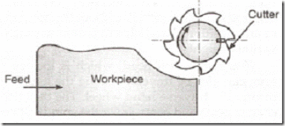
Horizontal Milling Machine Construction: The main part of the machine is the base, Column, Knee, Saddle, Table, Overarm, Arbor Support, and Elevating Screw.
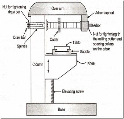
1. Base: It gives support and rigidity to the machine and also acts as a reservoir for the cutting fluids.
2. Column: The column is the main supporting frame mounted vertically on the base. The column is box-shaped, heavily ribbed inside, and houses all the driving mechanisms for the spindle and table feed
3. Knee: The knee is a rigid casting mounted on the front face of the column. The knee moves vertically along the guideways and this movement enables to adjust the distance between the cutter and the job mounted on the table. The adjustment is obtained manually or automatically by operating the elevating screw provided below the knee.
4. Saddle: The saddle rests on the knee and constitutes the intermediate part between the knee and the table. The saddle moves transversely, i.e., crosswise (in or out) on guideways provided on the knee.
5. Table: The table rests on guideways in the saddle and provides support to the work. The table is made of cast iron, its top surface is accurately machined and it carriers T-slots that accommodate the clamping bolt for fixing the work. The worktable and hence the job fitted on it is given motions in three directions:
a). Vertical (up and down) movement is provided by raising or lowering the knee.
b). Cross (in or out) or transverse motion provided by moving the saddle concerning the knee.
c). Longitudinal (back and forth) motion provided by hand wheel fitted on the side of the feed screw.
In addition to the above motions, the table of a universal milling machine can be swiveled 45° to either side of the center line and thus fed at an angle to the spindle.
6. Overarm: The Overarm is mounted at the top of the column and is guided in perfect alignment by the machined surfaces. The Overarm is the support for the arbor.
7. Arbor support: The arbor support is fitted to the Overarm and can be clamped at any location on the Overarm. Its function is to align and support various arbors. The arbor is a machined shaft that holds and drives the cutters.
8. Elevating screw: The upward and downward movement to the knee and the table is given by the elevating screw that is operated by hand or an automatic feed.
Operations that can be performed in a Milling Machine:
There are several types of operation that can be performed in a milling machine, and those are:
- Plain Milling Operation
- Face Milling Operation
- End Milling Operation
- For Milling Operation
- T-slot Milling Operation
- Side Milling Operation
- Gear Milling Operation
- Straddle Milling Operation
- Grooves Milling Operation
- Gang Milling Operation
1) Plain Milling Operation:
It is the operation of producing a plain, flat, horizontal surface, parallel to the axis of rotation.
This operation is also known as slab milling.
This operation is very common and done in almost all jobs.
This can be carried out on every mill machine.
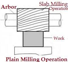
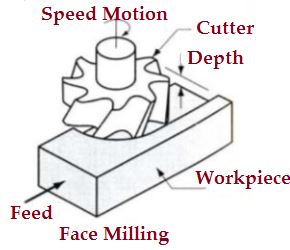
2) Face milling Operation:
This machining operation is done on the surfaces which are perpendicular to the axis of the cutter. The operation is performed by the face milling cutter mounted on the stub arbor of the machine.
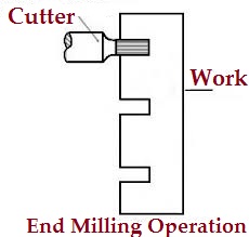
3) End milling operation:
It is the process of producing flat surfaces that may be horizontal, vertical, and at an angle taking worktable as a reference.
4. Side milling
- It is the machining process that produces a flat vertical surface at the sides of a workpiece.
5. Slot milling
- This is an operation of producing slots like T– slots, Plain- slots, etc.
6. Angular milling
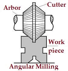
- It is the operation of producing all types of angular cuts like V- notches, grooves, serrations, and angular surfaces.
- E.g. Production of V- Blocks, etc.
7. Form milling
- This is the process of machining special contour ( outline ) composed of curves, straight lines, or entirely of curves at a single cut.
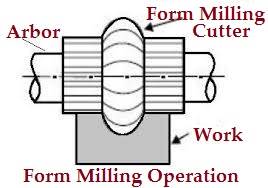
- This operation is accomplished by using convex, concave, and corner rounding milling cutters.
- In the wake of machining, the shaped surface is checked by a layout measure.
8. Straddle milling
- It is a process in which two side cutters are used to machining two opposite sides of a workpiece simultaneously.
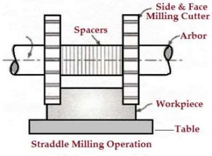
- Straddle milling is very common to produce square or hexagonal surfaces.
9. Gang milling
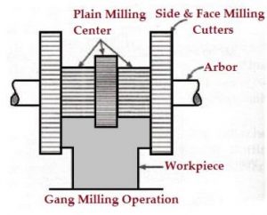
- It is the machining process in which two or more milling cutters are used together to perform different operations simultaneously.
10. Profile milling
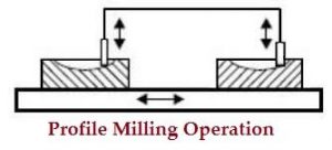
- It is the operation of reproduction of an outline of a template or complex shape of a master die on a workpiece.
11. Sawmilling
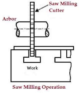
- Sawmilling is the operation of the production of narrow slots or grooves on a workpiece by using a sawmilling cutter.
12. Gear milling
- The gear cutting operation is performed in a milling machine by using a form relieving cutter.
- The cutter may be a cylindrical type or end mill type. The cutter profile corresponds exactly with the tooth space of the gear.
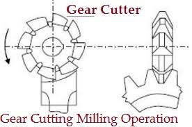
- Similarly separated rigging teeth are cut on an apparatus clear by holding the work on an all-inclusive isolating head and afterward ordering it.
13. Helical milling
- Helical milling is the operation of the production of helical flutes or grooves around the periphery of a cylindrical or conical workpiece.
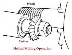
- The usual examples of work performed by helical milling operations are the Production of helical milling cutters, helical gears, cutting helical grooves or flutes on a drill blank or a reamer.
14. Cam milling
- The Cam milling is the operation of production of cams in a milling machine by the use of a universal dividing head and a vertical milling attachment.
- The axis of the cam can be set from zero to ninety degrees about the surface of the table for obtaining different rise of the cam.
- The cams are used to open and close valves in the internal combustion engines.
15. Thread milling
- Thread milling is the operation of the production of threads by using a single or multiple threads milling cutters.
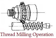
- The operation is performed in special thread milling machines to produce accurate threads in small or large quantities.
The advantages of the Milling machine:
In the milling machine there are the following advantages, those are:
- Ideal for the production of individual pieces and small batches.
- Capable of producing complex shapes with the use of multitooth, as well as a single point, cutting tools.
- Operation cost can be very modest given general-purpose equipment and cutters are used.
Milling Machine Disadvantages:
These are the following disadvantages of a milling machine:
- It is more costly than casting, cold forming, extrusion, etc. If these processes can provide the flatness, surface finish, and dimensional accuracy required for the part.
- For mass production, it becomes economically necessary to use special-purpose machines.
- They may cost millions of dollars but the cost is justifiable when handling labour which is virtually eliminated and machining accuracy and repeatability is ensured.
The applications of Milling Machine:
These are the following applications of the milling machine:
- These machines are used to make gears.
- Usually used to a machined flat surface but can also produce irregular surfaces.
- Used to produce the groove or slot.
- Modern mill machine cut superalloys, titanium, tensile steel to closer tolerance, a greater accuracy, and a faster rate.
- This machine is used to design metal and other materials.
a) Welding process:
Welding is a fabrication process whereby two or more parts are fused through heat, pressure, or both forming a join as the parts cool. Welding is usually used on metals and thermoplastics but can also be used on wood. The completed welded joint may be referred to as a weldment
Welding is the process by which two pieces of metal can be joined together. The process of welding doesn’t merely bond the two pieces together as in brazing and soldering, but, through the use of extreme heat and sometimes the addition of other metals or gases, causes the metallic structures of the two pieces to join together and become one. There are some different welding methods, including spot welding, metal inert gas (MIG), and tungsten inert gas, which are forms of gas metal arc welding, arc welding, and gas welding, to name a few. Welding can even be done underwater.
There are a variety of different processes with their techniques and applications for industry, these include:
1) Arc
This category includes some common manuals, semi-automatic and automatic processes. These include metal inert gas (MIG) welding, stick welding, tungsten inert gas (TIG) welding also known as gas tungsten arc welding (GTAW), gas welding, metal active gas (MAG) welding, flux-cored arc welding (FCAW), gas metal arc welding (GMAW), submerged arc welding (SAW), shielded metal arc welding (SMAW) and plasma arc welding.
These techniques usually use filler material and are primarily used for joining metals including stainless steel, aluminum, nickel and copper alloys, cobalt, and titanium. Arc welding processes are widely used across industries such as oil and gas, power, aerospace, automotive, and more.
Friction
Friction welding techniques join materials using mechanical friction. This can be performed in a variety of ways on different welding materials including steel, aluminum, or even wood.
The mechanical friction generates heat which softens the materials which mix to create a bond as they cool. How the joining occurs is dependant on the exact process used, for example, friction stir welding (FSW), friction stir spot welding (FSSW), linear friction welding (LFW), and rotary friction welding (RFW).
Friction welding doesn't require the use of filler metals, flux, or shielding gas.
Friction is frequently used in aerospace applications as it is ideal for joining otherwise 'non-weldable' light-weight aluminum alloys.
Friction processes are used across industries and are also being explored as a method to bond wood without the use of adhesives or nails.
Electron Beam
This fusion joining process uses a beam of high-velocity electrons to join materials. The kinetic energy of the electrons transforms into heat upon impact with the workpieces causing the materials to melt together.
Electron beam welding (EBW) is performed in a vacuum (with the use of a vacuum chamber) to prevent the beam from dissipating.
There are many common applications for EBW, as can be used to join thick sections. This means it can be applied across some industries from aerospace to nuclear power and automotive to rail.
Laser
Used to join thermoplastics or pieces of metal, this process uses a laser to provide a concentrated heat ideal for barrow, deep welds, and high joining rates. Being easily automated, the high welding speed at which this process can be performed makes it perfect for high volume applications, such as within the automotive industry.
Laser beam welding can be performed in the air rather than in a vacuum such as with electron beam joining.
Resistance
This is a fast process that is commonly used in the automotive industry. This process can be split into two types, resistance spot welding, and resistance seam welding.
Spot welding uses heat delivered between two electrodes which are applied to a small area as the workpieces are clamped together.
Seam welding is similar to spot welding except it replaces the electrodes with rotating wheels to deliver a continuous leak-free weld.
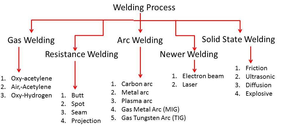
In general, various welding processes are classified as follows.
1: Gas Welding
(a): Air Acetylene
(b): Oxy-Acetylene
(c): Oxy Hydrogen Welding
2: Arc Welding
(a): Carbon Arc welding
(b); Plasma Arc welding
(c): Shield Metal Arc Welding
(d): T.I.G. (Tungsten Inert Gas Welding)
(e): M.I.G. (Metal Inert Gas Welding)
3: Resistance Welding:
(a): Spot welding
(b): Seam welding
(c): Projection welding
(d): Resistance Butt welding
(e): Flash Butt welding
4: Solid State Welding:
(a): Cold welding
(b): Diffusion welding
(c): Forge welding
(d): Fabrication welding
(e): Hot pressure welding
(f): Roll welding
5: Thermo Chemical Welding
(a): Thermit welding
(b): Atomic welding
6: Radiant Energy Welding
(a): Electric Beam Welding
(b): Laser Beam Welding
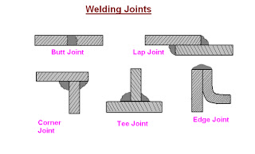
Welding Joints
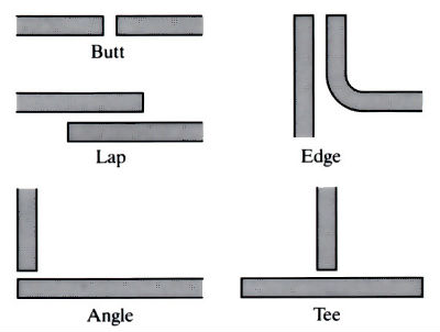
Different types of welding joint are classified as butt, lap, Corner, tee, and edge joint which are shown in the figure.
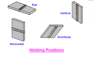
Iii) Manual metal arc welding
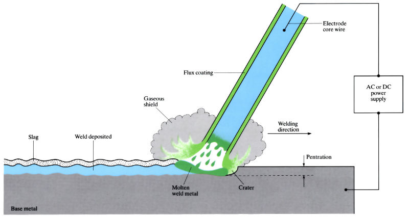
Manual metal arc welding (MMA or MMAW), also known as shielded metal arc welding (SMAW), flux shielded arc welding, or stick welding, is a process where the arc is struck between an electrode flux coated metal rod and the workpiece. Both the rod and the surface of the workpiece melt to create a weld.
Manual metal arc welding was first invented in Russia in 1888. It involved a bare metal rod with no flux coating to give a protective gas shield. The development of coated electrodes did not occur until the early 1900s when the Kjellberg process was invented in Sweden and the Quasi-arc method was introduced in the UK. It is worth noting that coated electrodes were slow to be adopted because of their high cost. However, it was inevitable that as the demand for sound welds grew, manual metal arc became synonymous with coated electrodes. When an arc is struck between the metal rod (electrode) and the workpiece, both the rod and workpiece surface melt to form a weld pool of molten metal. Simultaneous melting of the flux coating on the rod will form gas and slag which protects the weld pool from the surrounding atmosphere. The slag will solidify and cool and must be chipped off the weld bead once the weld run is complete (or before the next weld pass is deposited).
The process allows only short lengths of weld to be produced before a new electrode needs to be inserted in the welding electrode holder. Weld penetration is low and the quality of the finished weld deposit is highly dependent on the skill of the welder.
MMA welding (flux-coated electrode)
An electric arc is produced between a metal electrode, carrying a high current, and the workpiece to be joined. Under the intense heat of the arc temperature (2700–5500°C), a small area of the base metal is brought to the melting point. At the same time, the end of the electrode is melted and droplets of molten metal pass through the arc to the base metal. A flux coating on the electrode provides a gaseous shielding against oxidation.

Manufacture:
- Either alternating (a.c.) or direct (d.c.) current is used for MMA welding. When a.c. Is used, the arc must re-ignite at each half-cycle, as the polarity is reversed. This causes some instability of the arc, which can be alleviated by the use of arc-stabilizing agents in the flux coating. When D.C. Is used, there is a choice of polarity – the positive pole of the arc is the hottest.
- Arc voltages are maintained between 14 and 45 V, with open-circuit voltages of 50–100 V. Power sources range from 30 to 500 Amps a.c. Or d.c.
- Coated electrodes contain slag-forming ingredients (that produce a fluid coating over the weld as it cools) and gas-forming ingredients (that generate atmospheres of CO2, CO, or H2 around the arc). Principal materials used in electrode coatings include:
- Carbonaceous material of the cellulose type (C6 H10 O5 ) n – produces a shielding gas (CO).
- Silica (SiO2) – combines with metallic oxides to form slag.
- Titanium oxide (TiO2) – to stabilize the arc.
- Calcium carbonate (CaCO3) – decomposes to form CaO, and hence a basic slag.
- Calcium fluoride (CaF2)– increases slag fluidity.
- Sodium oxide (Na2O) – acts as a coating binder and promotes slag fluidity.
- Ferro-silicon – acts as deoxidant.
- Iron powder – increases the rate of deposition.
- Sizes of welding machines are designated according to their output rating, which may range from 150 to 1000 Amps.
- Deposition rates in range 2–5 kg h-1.
Materials:
- Most engineering metals and alloys can be welded by the MMA welding process (a very versatile process).
- In welding carbon and low alloy steels, the coated electrodes are usually of low carbon steel. For alloy steels prone to the formation of hard and brittle martensite on cooling, low alloy steel electrodes are used. Also, these steels are prone to hydrogen embrittlement and coatings must be free from hydrogen-forming cellulose. Instead, TiO2 and CaCO3 are added to the coating. Austenitic compositions (up to 25% chromium and 20% nickel) are also useful to prevent martensite formation.
- Cast irons are welded with nickel-rich or monel electrodes (Ni - Cu).
- Most non-ferrous metals and alloys are welded with electrodes of a composition similar to the metal being welded. Aluminum alloy electrodes are coated with fluxes consisting of mixtures of fluorides and chlorides to dissolve the aluminum oxide Al2O3 surface layer. The precipitation hardening Al-Mg-Si alloys are now welded by the TIG and MIG processes. Copper, copper-tin (bronzes) and copper-zinc (brasses) alloys have large coefficients of thermal conductivity, so require greater amounts of heat and need pre-heating before MMA welding (up to 250–450°C). Nickel alloys can be welded with pre-heated electrodes.
Design:
- There are five main types of welded joints: butt, corner (angle), edge, fillet (or tee), and lap joints.
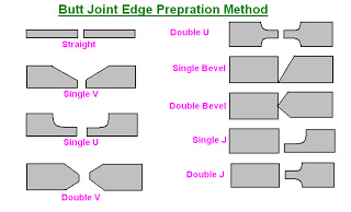
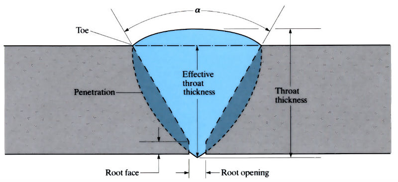
- Square-ended butt joints can be made in metal thicknesses up to 5mm. Single “V” butt welds are made in metal plate, with thicknesses of 5–25 mm. The minimum included angle (α) is 60° with a root opening of 0–3mm and a root face of 0–3mm.
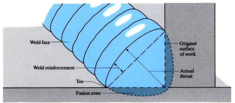
- Fillet welds are used to fill in a corner and are the most common welds in structural work (T-joints).
IV) Spot welding:
Spot welding (also known as resistance spot welding) is a resistance welding process. This welding process is used primarily for welding two or more metal sheets together by applying pressure and heat from an electric current to the weld area.
It works by contacting copper alloy electrodes to the sheet surfaces, whereby pressure and electric current are applied and heat is generated by the passage of current through resistive materials such as low carbon steels.
A form of resistance welding, spot welding is one of the oldest welding processes whereby two or more sheets of metal are welded together without the use of any filler material.
The process involves applying pressure and heat to the weld area using shaped alloy copper electrodes which convey an electrical current through the weld pieces. The material melts, fusing the parts at which point the current is turned off, pressure from the electrodes is maintained and the molten “nugget” solidifies to form the joint.
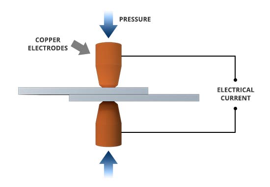
The welding heat is generated by the electric current, which is transferred to the workpiece through copper alloy electrodes. Copper is used for the electrodes as it has high thermal conductivity and low electrical resistance compared to most other metals, ensuring that the heat is generated preferentially in the workpieces rather than the electrodes.
The amount of heat depends on the thermal conductivity and electrical resistance of the metal as well as the amount of time the current is applied. This heat can be expressed by the equation:
Q = I2Rt
In this equation “Q” is heat energy, “I” is current, “R” is electrical resistance, and “t” is the time for which the current is applied.
Spot welding has applications in some industries, including automotive, aerospace, rail, white goods, metal furniture, electronics, medical building, and construction.
Given the ease with which spot welding can be automated when combined with robots and manipulation systems, it is the most common joining process in high volume manufacturing lines and has in particular been the main joining process in the construction of steel cars for over 100 years.



Iv) Oxyacetylene welding:
Oxy-Acetylene (OA) welding is one of the many types of welding. It is extremely versatile, and with enough skill and practice, you can use this type of welding for virtually any metal. The oxy-acetylene flame burns at 6000 F and is the only gas flame that is hot enough to melt all commercial metals. Oxy-acetylene welding is simple in concept - two pieces of metal are brought together, and the touching edges are melted by the flame with or without the addition of a filler rod.
Advantages of Oxy-Acetylene Welding
It's easy to learn.
The equipment is cheaper than most other types of welding rigs (e.g. TIG welding)
The equipment is more portable than most other types of welding rigs (e.g. TIG welding)
OA equipment can also be used to "flame-cut" large pieces of material.
Disadvantages of Oxy-Acetylene Welding:
OA weld lines are much rougher in appearance than other kinds of welds and require more finishing if neatness is required.
OA welds have large heat-affected zones (areas around the weld line that have had their mechanical properties adversely affected by the welding process)
Materials Suitable for OA Welding
Most steels
Brass
Preparation:
1) Assemble all of the materials needed to make the weld. This includes parts, OA equipment, fixturing, tools, safety mask, gloves, and filler rod.
2) Clean the parts to be welded to remove any oil, rust, or other contaminants. Use a wire brush if needed to remove any rust.
3) Assemble and fixture the parts in place - the parts need to be stable for a good weld line. Ceramic bricks, vise grips, pliers, and clamps are available in a file cabinet in the welding room for fixturing.
4) Select the nozzle you plan to use for welding. Nozzles come in a variety of sizes, from 000 (for a very small flame - typically used for thin materials) to upwards of 3 (for a large flame - needed for thick materials). Larger nozzles produce larger flames and, in general, are more appropriate for thicker material. Choosing the right size nozzle becomes easier with more experience.
5) Clean the nozzle. Carbon deposits can build up on the nozzles which interfere with the flame quality and cause backfiring. The cleaning tool has a wide flat blade (with a file-like surface) which is used to clean carbon deposits on the exterior of the nozzle. Use it to scrape any deposits from the flat face of the tip. Use the wire-like files to clean the interior of the nozzle. Pick the largest wire which will fit inside the nozzle and scrape the edges of the hole to remove any carbon build-up.
6) Attach the nozzle to the gas feed line by hand. Don't over-torque - the nozzle and hose fitting are both made of brass which doesn't stand up well to abuse. A snug, finger tight fit is sufficient.
7) Check the pressure levels in the oxygen and acetylene tanks. There should be at least 50 psi in the acetylene tank. The oxygen tank can be used until it is empty. . Note: The oxygen used in OA welding is NOT for human consumption. It contains contaminants that could be unhealthy if taken in large quantities
Adjusting the flame
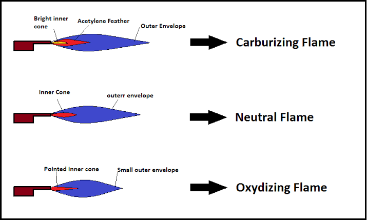
The blue flame will be divided into 3 different colour regions - a long yellowish tip, a blue middle section, and a whitish-blue intense inner section.
There are three types of flames as described below:
1) Neutral - This type of flame is the one you will use most often in the metalwork room. It is called “neutral” because it has no chemical effect upon the metal during welding. It is achieved by mixing equal parts oxygen and acetylene and is witnessed in the flame by adjusting the oxygen flow until the middle blue section and inner whitish-blue parts merge into a single region.
2) Reducing / Carburising flame - If there is excess acetylene, the whitish-blue flame will be larger than the blue flame. This flame contains white hot-carbon particles, which may be dissolved during welding. This “reducing” flame will remove oxygen from iron oxides in steel.
3) Oxidizing flame - If there is excess oxygen, the whitish-blue flame will be smaller than the blue flame. This flame burns hotter. A slightly oxidizing flame is used in brazing, and a more strongly oxidizing flame is used in welding certain brasses and bronzes.
Safety features incorporated into oxy-acetylene equipment
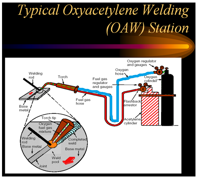
The Acetylene tank contains an absorbent substance called Acetone. Acetone can absorb 25 times its volume of Acetylene.
Colour coding: oxygen cylinder is black and acetylene is maroon, hoses and regulators are colour coded with oxygen as blue and acetylene as red.
The acetylene connection on the torch has a left-hand thread and the oxygen connection has a right-hand thread to prevent interchange.
Flashback arrestors are placed on the acetylene and oxygen lines to prevent feedback of gases.
Regulators are designed to fit only on acetylene or high-pressure oxygen cylinders and cannot be changed
b) Brazing:
Among various joining processes, brazing is a particular variant that allows the joining of two different components without melting either of the materials (base materials). The brazing process is characterized by the creation of a liquid that is made to flow into and fill the spaces between the components to be joined and then allowed to solidify.
The liquid, appropriately termed as “the filler” since it fills the space between the joint, has a comparatively lower melting point than the materials being joined. Hence, no melting of the substrate occurs. Consider this as being a liquid glue to join two materials together. The only difference is that the glue has to be melted before it can be activated for joining.
Capillary action, wetting, and possible chemical reactions during the process ensure a powerful metallurgical bond due to bonding at the atomic level. This is why brazing is often the first choice in joining simple and complex structures ranging from the radiator cores in your automobiles to honeycomb sandwich cores in the aerospace industry.
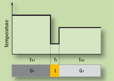
The temperature profile during the brazing process The brazed joint is always at a lower temperature as compared to the melting temperature of the base materials.
Ii) Procedure:
To carry out the brazing process, a brazing torch, filler rod, flux, gaseous fuels (oxygen and acetylene) to get carburizing flame are required.
The procedure of the brazing operation is explained below.
1. First, the surfaces to be joined are cleaned, and dust, oil, grease, oxide layers, and other foreign substances are removed.
2. Apply a suitable flux at where the brazing is to be carried out. This is used to avoid the base metal oxidation, and it helps to flow the filler material easily by capillary action.
3. Then, the filler material is placed at the place where brazing is to be carried out.
4. By using a carburizing flame, raise the temperature above the melting point of the filler material.
5. After raising the temperature of filler material, then molten metal is formed, and it flows into the gap by capillary action.
6. Allow the filler material and base metals to solidify.
7. Then, cool the base metals slowly to get a strong bonding.
8. The leftover fluxes are cleaned immediately after the brazing process because it is corrosive.
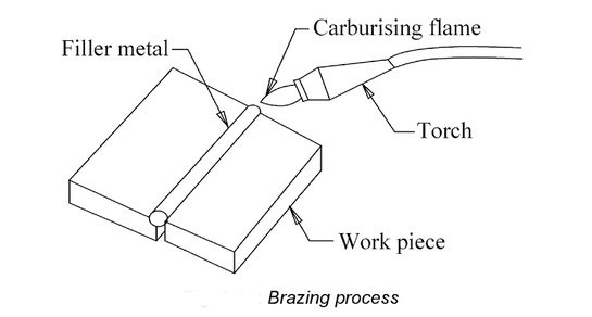
Brazing processes themselves are often classified according to the sources of heating. Chemical heat sources for melting include Torch Brazing, Furnace Brazing, Exothermic Brazing, and Vapour- Phase Brazing. Electrical sources are often widely used in an automated industrial setup and include Chemical Dip Brazing, Molten Melt Brazing, Induction Brazing, Infrared Brazing, Electron Beam Brazing, and Diffusion Brazing.
Ii) Filler material
The filler material has to be of a different composition than the material of the components to be joined. The choice of the filler material largely depends on the materials that are to be joined together. Braze fillers can be ceramic for joining ceramics to ceramics, or metallic for joining metals to ceramics or themselves. The process is clean, efficient, and easily reproducible. The brazing process is particularly effective since it involves a substantial degree of inter-diffusion between the filler and the substrate. You can consider it as atoms moving from the filler material to the base material.
The filler material should possess distinctive characteristics to be used for brazing. It should have the required mechanical, chemical, and physical properties that can be imparted to the braze joint. Most importantly, the filler material should have a coefficient of thermal expansion (CTE) close to that of the base materials. This ensures that no thermal stresses are generated after solidification.
The melting point of the filler material should be lower than the one of the base materials and the molten liquid formed during the melting process should have the appropriate fluidity which can enable it to flow and distribute properly into the joints via the capillary action. Also, the composition of the filler material must be homogeneous and stable to inhibit the separation of the constituents.
Iii) Advantages and disadvantages:
Advantages of Brazing:
1. brazing is an economical and straightforward process.
2. A brazing process can join dissimilar metals.
3. Low gauge or thin section plates are joined very easily, but such workpieces cannot be joined by welding.
4. Metals with different thicknesses can be joined easily.
5. Joints produced with the brazing process are better in appearance because stresses will not be induced, no metallurgical damages, and distortion of the plate will take place.
6. Radiators, containers, and tanks, pipe fittings, heat exchangers can be brazed easily. But this cannot be done by welding.
7. Brazing produces leak-proof and pressures tight joints.
8. Thin sheets, pipes, and gauges that can’t be joined by welding can be joined by brazing.
9. Complex assemblies can be fabricated by this method.
10. A brazed component can preserve protective metal coating.
11. Brazing can be done on the cast and wrought materials.
12. Corrosion resistance joints can be produced by this method.
13. Brazing preserves metallurgical characteristics of material better than welding.
14 After brazing a component maintains more precision tolerances than welding.
15. Brazing processes can be automated for bulk production.
16. Non-metals can be joined to metals.
Disadvantages of Brazing:
1. Heavy sections can be joined by a brazing process. It is suitable for small and thin section plates only.
2. Skilled labour is required for brazing.
3. Brazing results in low strength joints compared to welding.
4. It requires tightly mating parts.
5. It requires proper cleaning.
6. Size of the job is limited.
7. Joints are not successful at elevated temperatures.
8. Colour of the filler metal may not match with that of the base metal.
Iii) Applications
Following are the applications of brazing:
- It is used in vacuum interrupters.
- It is used in transport applications.
- Used in constructions.
- It is helpful in medical equipment.
- Used in art and jeweler
c) Soldering
Soldering is the process of joining two metal pieces with the help of suitable filler material and at a temperature below 450°C. Or it is a process of metal joining at a low temperature of about below 450° C.
The main advantages of soldering are that two dissimilar metals can also be joined. The filler metal used for soldering is called solder, and it is an alloy of lead and tin. Different solder can be obtained by varying the proportions of lead and tin in the alloy.
The main characteristic of solder is that it can melt at low temperature because its melting point is low. Soldering operation does not involve melting the workpieces. The solders available in the market are in the form of soft solder and hard solder. Soft solder is made up of lead and tin, and hard solder is made up of copper, tin, and silver. These metals are mixed in different proportions to get a variety of solders.
A suitable flux is used in the soldering process to clean and remove the impurities produced due to oxidation. Usually, zinc chloride is used as a flux for the soldering process. Soldering finds its applications in automotive and fabrication industries and is used in automotive radiators or tin cans.
It is also used in Electrical Connections in television and radio, joining thermally sensitive components, and sometimes used to join dissimilar metals.
Ii) Soldering Process Procedure.
The soldering equipment is soldering iron, solder, or filler rod, power supply. The procedure of soldering is explained as below.
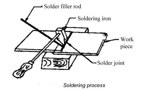
1. The workpieces must be cleaned before the soldering process. The presence of oil, grease, dust, wetness, rust, etc., is removed.
Sometimes suitable cleaning agents are used for cleaning the soldering surfaces. The presence of foreign materials on the surfaces to be soldered leads to weak joints lowers the strength of the joint produced.
The commonly used cleaning agent is flux, such as borax or resin. This flux helps to remove all unwanted material from the surfaces of the workpiece and get strong bonding.
2. First, the soldering iron tip (made up of copper) is cleaned and heated. It is then applied with solder using resin. This will create a thin film of solder on the soldering iron tip and is called tinning.
3. Once the solder is taken in the soldering iron tip, the soldering iron tip is heated, and the solder will be melted. This melted solder then flows over the joining area and fills the gap. Finally, the joint formed is allowed to cool slowly.
After complete soldering, the soldered surfaces must be cleaned. To clean the leftover flux, a suitable chemical is used, or it is cleaned by using cotton waste.
Iii) Advantages and disadvantages:
Advantages of soldering:
1. Dissimilar metals can be joined.
2. It is simple, low cost, flexible, economical, and user-friendly.
3. The life of the solder will be more.
4. Low amount of power is required to heat the soldering iron.
5. The soldering can be done at low temperature, and controlling is very easy.
6. Soldered joints can be dismantled.
Disadvantages of Soldering:
1. The soldering process cannot join heavy sections. It is suitable for small parts only.
2. Solders are costlier, and soldering requires proper solder to get strong bonding.
3. Skilled labour is required for soldering.
Iv) Rivets and their types often small machine components are joined together to form a larger machine part. The design of joints is as important as that of machine components because a weak joint may spoil the utility of a carefully designed machine part. Mechanical joints are broadly classified into two classes viz., non-permanent joints and permanent joints. Non-permanent joints can be assembled and dissembled without damaging the components. Examples of such joints are threaded fasteners (like screw-joints), keys and couplings, etc.
Permanent joints cannot be dissembled without damaging the components. These joints can be of two kinds depending upon the nature of the force that holds the two parts. The force can be of mechanical origin, for example, riveted joints, joints formed by press or interference fit, where two components are joined by applying mechanical force. The components can also be joined by molecular force, for example, welded joints, brazed joints, joints with adhesives, etc.
Not until long ago riveted joints were very often used to join structural members permanently. However, significant improvement in welding and bolted joints has curtained the use of these joints. Even then, rivets are used in structures, ship bodies, bridges, tanks, and shells, where high joint strength is required.
2. Rivets and Riveting:
A Rivet is a short cylindrical rod having a head and a tapered tail. The main body of the rivet is called shank (see figure 10.1.1). According to Indian standard specifications, rivet heads are of various types. Rivets heads for general purposes are specified by Indian standards IS: 2155-1982 (below 12 mm diameter) and IS 1929-1982 (from 12 mm to 48 mm diameter). Rivet heads used for boiler works are specified by IS: 1928-1978. To get dimensions of the heads see any machine design handbook.
Head
Shank
Tail
Rivet and its parts
Riveting is an operation whereby two plates are joined with the help of a rivet. Adequate mechanical force is applied to make the joint strong and leak proof. Smooth holes are drilled (or punched and reamed) in two plates to be joined and the rivet is inserted. Holding, then, the head through a backing up bar as shown in the figure, necessary force is applied at the tail end with a die until the tail deforms plastically to the required shape.
Depending upon whether the rivet is initially heated or not, the riveting operation can be of two types:
(a) cold riveting- riveting is done at ambient temperature and
(b) hot riveting - rivets are initially heated before applying force. After riveting
Is done, the joint is heat-treated by quenching and tempering. To ensure leak-proofness of the joints, when it is required, an additional operation like caulking is done.
Backing up bar Die
Riveting operation
3. Types of riveted joints and joint efficiency:
Riveted joints are mainly of two types
1. Lap joints
2. Butt joints
3.1 Lap Joints:
The plates that are to be joined are brought face to face such that an
Overlap exists.
References:
1. Engineering Thermodynamics, P K Nag, The Tata McGraw-Hill Companies
2. Mechanical Engineering Design, Joseph E Shigley, Charles R Mischke, The Tata McGraw-Hill Companies
3. Production Technology Vol. I & II, O.P. Khanna, Dhanpat Ray Publications