UNIT-1
Resultant of coplanar forces
1.1.1 Basic units, SI units, Rigid body, particle
Fundamental Concepts
1> Particle
It is a material point which contains definite quantity of matter without dimension.
2> Rigid Body
It is a body which does not undergo any deformation (change in shape and size) under the action of external force.
Combination of large no of particles which remains at fixed distance from each other when external force is applied or removed.
3> Force
An action which tends to change the state of rest of body or motion of body on which it acts.
System of Units:
A system of units is a set of related units that are used for calculations. The system includes base units, which represent base dimensions, and derived units, which represent products of powers of base dimensions. Some units exist in more than one system of units. For example, there is a unit of mass named the ounce in the avoirdupois and troy systems of units. To distinguish between these units in Maple, each unit has a context. For example, the ounce[avoirdupois] and ounce[troy] are units of mass. For additional information about dimensions, units, and contexts, see Details.
For example, in the MKS system, the base units are the meter, kilogram, and second, which represent the base dimensions of length, mass, and time, respectively. In this system, the unit of speed is the meter per second. However, the unit of force, the kilogram meter per square second, is named the newton.
In the FPS system, the base units are the foot, pound, and second, which represent the base dimensions of length, mass, and time, respectively. The complex unit of speed and derived unit of force are the foot per second and pound, respectively, where 1 pound equals 1 foot pound per second squared.
Systems of Units
The set of systems of units in Maple is:
SI (International System of Units) (meter-kilogram-second-ampere-kelvin-mole-candela)
FPS (foot-pound-second)
MKS (meter-kilogram-second)
CGS (centimetre-gram-second)
EMU (Electromagnetic) (centimetres-gram-second-ampere)
ESU (Electrostatic) (centimetre-gram-second-coulomb)
Atomic (bohr-electron mass-atomic second-electron)
MTS (meter-tonne-second)
1.1.2 Scalar quantities, vector quantities, Idealization of engineering problems
Scalar Quantities: The physical quantities which are specified with the magnitude or size alone are scalar quantities. For example, length, speed, work, mass, density, etc.
Vector Quantities: Vector quantities refer to the physical quantities characterized by the presence of both magnitude as well as direction. For example, displacement, force, torque, momentum, acceleration, velocity, etc.
Characteristics of Vectors
The characteristics of vectors are as followed –
- They possess both magnitudes as well as direction.
- They do not obey the ordinary laws of Algebra.
- These changes if either the magnitude or direction change or both change.
Unit Vector
A unit vector is that vector which is a vector of unit magnitude and points in a particular direction. The unit vector in the direction of  and is defined by

The unit vectors along the x, y and z-axis is ^i, ^j, and ^k respectively.
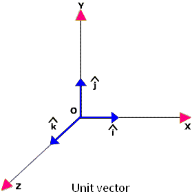
Fig 1
Equal Vectors
Vectors A and B are equal if | A | = | B | as well as their directions, are same.
Zero Vectors
Zero vectors are a vector with zero magnitudes and an arbitrary direction is a zero vector. It can be represented by O and is a Null Vector.
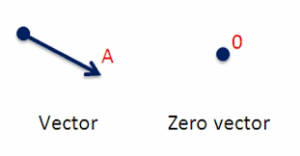
Fig 2
Negative of a Vector
The vector whose magnitude is same as that of a (vector) but the direction is opposite to that of a (vector) is referred to as the negative of a (vector ) and is written as – a ( vector ).
Parallel Vectors
A and B are said to be parallel vectors if they have the same direction, or may or may not have equal magnitude (A || B ). If the directions are opposite, then A (vector) is anti-parallel to B ( vector ).
Coplanar Vectors
If the vectors lie in the same plane or they are parallel to the same plane, the vectors are said to be coplanar. If not, the vectors are said to be non – planar vectors.
Displacement Vectors
The displacement vector refers to that vector which gives the position of a point with reference to a point other than the origin of the coordinate system.
Vector Addition and Subtraction
After understanding what is a vector, let’s learn vector addition and subtraction. The addition and subtraction of vector quantities does not follow the simple arithmetic rules. A special set of rules are followed for the addition and subtraction of vectors. Following are some points to be noted while adding vectors:
- Addition of vectors means finding the resultant of a number of vectors acting on a body.
- The component vectors whose resultant is to be calculated are independent of each other. Each vector acts as if the other vectors were absent.
- Vectors can be added geometrically but not algebraically.
- Vector addition is commutative in nature, i.e

Now, talking about vector subtraction, it is the same as adding the negative of the vector to be subtracted. TO better understand, let us look at the example given below. Let us consider two vectors  and
and  as shown in the figure below. We required to subtract
  from
from  It is just the same as adding
  and
and  The resultant is shown in the figure below
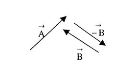
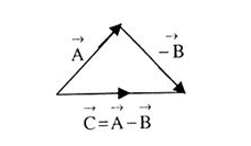
Fig 3
Vector Notation
For vector quantity usually, an arrow is used on the top like →v which represents the vector value of the velocity and also explains that the quantity has both magnitudes as well as direction.
Idealization of engineering problems
The mathematical description of a real engineering Problem can become very complex. Thus, idealization (or models) and assumptions are used in mathematics in order to simplify the application of the theory.
1) Particle: is a body of negligible dimensions. In the mathematical sense, a particle is a body whose dimensions are considered to be near zero so that we may analyse it as a mass concentrated at a point. We often choose a particle as a differential element of the body. We may treat a body as a particle when its dimensions are irrelevant to the description of its position or the action of forces applied to it. A body considered as a particle is taken as a unique point, which is generally the mass center of the body. A particle has mass but no shape and dimensions. In so doing, the principles of mechanics are reduced to a rather simplified form, since the geometry of the body will not be involved in the analysis of the problem. The line of actions of all the forces applied to the body must pass through this point.
Forces can only exert push – pull effects on a particle.
2) Rigid Body: is an idealized body composed of a large number of particles all of which always remain at fixed distances from each other. In addition to the tendency to move a body in the direction of its application, a force may also tend to rotate a body about an axis. A rigid body is assumed to undergo no deformation under the action of applied forces. Its shape and dimensions remain fixed under all loading conditions and at all times.
3) Point Force: is an idealized force assumed to act at a point on a body. A constant force exerted on a body by another is actually distributed over the area of contact between two bodies. If the area of contact is relatively small, the contact force between the two bodies may be considered as a point (concentrated) force.
Key points
1) Scalar Quantities: The physical quantities which are specified with the magnitude or size alone are scalar quantities. For example, length, speed, work, mass, density, etc.
2) Vector Quantities: Vector quantities refer to the physical quantities characterized by the presence of both magnitude as well as direction. For example, displacement, force, torque, momentum, acceleration, velocity, etc.
1.1.3 Force, law of transmissibility of force, moment of a force
Force [(F) or (P)]:-
It is an external agency which produces or tends to produce, destroy or tends to destroy motion.
OR
It is an external agent which changes or tends to change the state of motion of body.
It is a vector quantity.
Force is also known as rate of change of momentum.
As momentum = mass x velocity
But mass will never change, then
Force = mass x rate of change of velocity
= mass x Acceleration
F = P = ma
S.I. Unit: - Newton (N)
Kilo Newton (KN) = 103 N
Mega Newton (MN) = 106 N
Giga Newton (GN) = 103 N
Tera Newton (TN) = 1012 N
1 Kg Force:-
Force required producing unit gravitational acceleration on unit mass.
01 kg force = mass x Acceleration (gravity)
= 1 kg x 9.81 m / s2
= 9.81 kg.m / s2
1 kg.F = 9.81 Kg m / s2
1 kg.F = 9.81 N
I.e. 1 Kg = 9.81 N
Characteristics of Force:-
1>Magnitude: - The value of force i.e. 10N, 2KN, etc.
2>Direction: - Line of action & angle formed with fixed axis.
3>Nature of force or sense:-It means whether the force is push or pull.

Pull type force Push type force
Push: - Force acting towards the point
Pull: - Force acting away from the point.
4>Point of application: -
The point at which or through which the force acts.
Effects of Force: -
Force may produce following effects on the body.
1> It may change the state of body.
I.e. if body is at rest, force may bring it in motion or if body is in motion, force may accelerate it or force may stop it or may retard it.
2> It may produce internal stress in the body.
3> It may produce deformation in non-rigid body.
4> It may produce rotational effect in body.
5> It may keep the body in stable state (Equilibrium).
Law of transmissibility of force
The state of the rigid body will not change if force acting on a body is replaced by another force of same magnitude & direction acting anywhere on the body along the line of action of replaced force.
The value of force will not change along the Line of action of force within the body.

Fig 5
Moment of a force
Moment: - The turning effect produced by a force on the body on which it acts is called as Moment. Moment of force about any point is the product of magnitude of force and perpendicular distance of force from the point about which moment is to be taken.
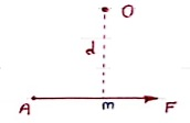 Let force F is applied at point A as shown & O is any point about which we want to take moment.
Fig 6
Thus from point O, draw OM line perpendicular to the line of action of force.
OM = d = Perpendicular distance between Force & point O.
Moment = M = F x d
Graphical representation of Moment: -
- Select suitable scale to locate the force graphically.
- Draw a line parallel to line of action of force. Length of this line can be calculated from selected scale.
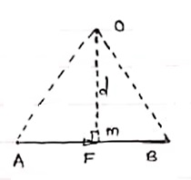 - Length of a line will be equal to magnitude of force. In the figure, Force F is represented by line AB.
- Now let O is the moment centre &
OM = d = perpendicular distance
By definition, Mo = F x d
Now join OA & OB, then
In Δ OAB
Area (ΔOAB) = ½ x AB x OM Fig 7
2 (Area of ΔOAB) = F x d = Mo
Thus the moment of any force about any point is numerically equal to twice area of triangle in which base represents force & height represents the perpendicular distance.
1.1.4 Couple, moment of a couple, resultant
Couple
A pair of two equal and opposite (unlike) parallel forces (of same magnitude) is known as couple.
Properties of Couple: -
1> Two unlike parallel, non-collinear forces of same magnitude will form couple.
2> Resultant of couple is always zero.
3> Moment of couple is product of one of the forces & lever arm of couple.
M = F x d
Lever arm of couple = ḻlar distance between couple forces.
4> Couple cannot be balanced by single force.
5> Couple can be balanced only by another couple of opposite nature.
6> Moment of couple is independent of moment centre. i.e. Ref. Point is not required to take moment of couple.
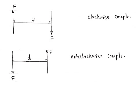
Fig 8
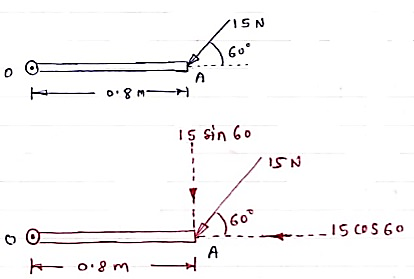 Q) A force of 15 N is applied at an angle of 600 to the edge of door as shown in figure. Find the moment of this force.
Solution:-
Resolving force at point B & then taking the moment about point O,
M0 = (15 Cos 60 x 0) + (15 Sin 60 x 0.8)
= 0 + 10.39
M0 = 10.39 N.m
Q) A 90 N force is applied to the control rod AB. Determine moment of this Force about point B.
Solution:-
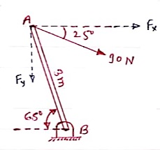 As we don’t know perpendicular distance between force & point ‘B ’, Let us resolve the force into two components.
X – Component of force
Fx = 90 Cos 25 = 81.567 N
Y – Component of force
Fy = 90 Sin 25 = 38.036
Now taking moments about point B
MB = [Fx x (3 Sin 65)] - [Fy x (3 Cos 65)]
MB = (81.65 x 2.72) – (38.036 x 1.27)
= 221.843 – 48.31
MB = 173.53 N.m
Examples on Non-concurrent forces & use of Varigon’s theorem
 1> Determine the resultant of the system of forces acting on a beam as shown in figure.
Fig 8
Above Force system is Non-concurrent force system.
Resolving the forces horizontally,
∑ Fx = - 20 Cos 60 = - 10 KN = 10 KN (toward left)
Resolving forces vertically,
∑Fy = - 20 – 30 – 20 Sin 60
= - 67.32 KN
∑Fy = 67.32 KN (downwards)
Resultant, R = √ (∑ Fx) 2 + (∑Fy) 2 = √10 2 + 67.322
R = 68.06 KN
Direction of Resultant,
Tanα = ∑Fy / ∑ Fx = 67.32 / 10.00
α = 81.550
Now taking moment about point A & using Varignon’s theorem.
∑MA = Moment of resultant A
(20 x 1.5) + (30 x 3) + (20 Sin 60 x 6) = (∑ Fx x 0 ) + (∑Fy x X)
223.92 = 67.32 x X
X = 223.92 / 67.32 = 3.326 m from point A
Ans
 Q) For a given force system, find the resultant in magnitude & direction. Also find the location of Resultant.
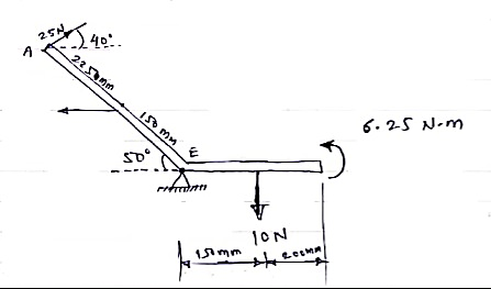
Solution

Resolving forces horizontally,
∑ Fx = - 15 + 25 Cos 40 = 4.15 N (toward right)
Resolving forces vertically,
∑Fy = 25 Sin 40 – 10
= 6.07 n (upward)
R = √(∑ Fx) 2 + (∑Fy)2
= √4.152 + 6.072
R = 7.35 N
Tanα = ∑Fy / ∑ Fx = 6.07 / 4.15
α= 55.640 - - - Angle made by resultant
To find exact position of R, let x is the perpendicular distance between R & point B.
Using Varignon’s theorem at point B.
R x X = ∑MB
= (10 x 150) – (15 x 150 Sin 50) + (25 x 375) – (6.25 x 1000)
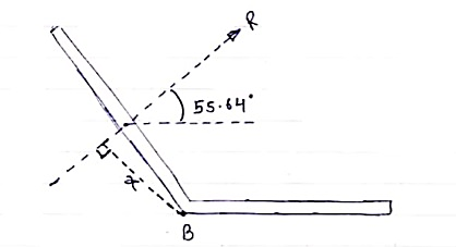 = 1500 – 1723.6 + 9375 – 6250
= 2901.4 N.mm (clockwise)
x = 2901.4 / R
= 2901.4 / 7.35
x = 394.75 mm from point B.
Moment of a couple
A couple is a pair of forces, equal in magnitude, oppositely directed, and displaced by perpendicular distance, d.
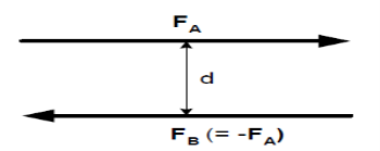
Fig 10
Since the forces are equal and oppositely directed, the resultant force is zero. But the displacement of the force couple (d) does create a couple moments. The moment, M, about some arbitrary point O can be calculated.
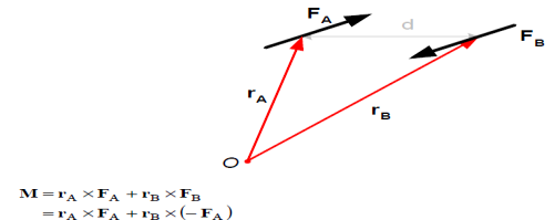
Fig 11
If point O is placed on the line of action of one of the forces, say FB, then that force causes no rotation (or tendency toward rotation) and the calculation of the moment is simplified

This is a significant result: The couple moment, M, depends only on the position vector r between forces FA and FB. The couple moment does not have to be determined relative to the location of a point or an axis.
Resultant Force:-
- If number of forces are acting simultaneously on a body, then it is possible to find out single force which could replace them, i.e. which would produce the same effect as produced by all given forces. This single force is called as Resultant force.
OR
- It is a single force which produces the same effect that is produced by number of forces when acting together.
Resultant is denoted by (R)
1.1.5 Parallelogram law of forces, triangle law of forces
Parallelogram law of forces: -
If two forces acting simultaneously on a particle be represented in magnitude & direction by two adjacent sides of parallelogram, then the diagonal passing through the point of intersection of two forces will represent the resultant in magnitude & direction.
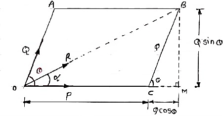
Fig 12
Consider two forces P & Q acting at a point represented by two sides OA & OC of parallelogram OABC.
Let, θ is the angle between two forces P & Q.
α be the angle between Force P & Resultant R.
Let’s draw a line BM perpendicular to OC which intersects OC at M.
In Δ CMB
Sin θ = BM / BC = BM / Q
BM = Q Sin θ
Also, Cos θ = CM / BC = CM / Q
CM = Q Cos θ
Now in Δ OMB,
We have, (OB) 2 = (OM) 2 + (BM)2
R2 = (OC + CM) 2 + (BM)2
R2 = (P + Q Cos θ) 2 + (Q Sin θ)2
= P2 + 2PQ Cos θ + Q2 Cos2 θ+ Q2 Sin2 θ
= P2 + 2PQ Cos θ + Q2(Cos2 θ+ Q2 Sin2 θ)
= P2 + 2PQ Cos θ + Q2
Taking sq. Root,
R = √P2 + Q2 + 2PQ Cos θ . . . . Magnitude
Tanα = Q Sin θ / P + Q Cos θ . . . . Direction.
Examples based on Parallelogram Law of forces:-
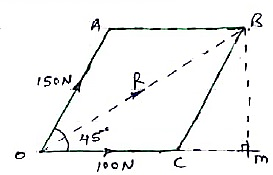 1> Two forces of 100 N & 150 N are acting simultaneously at a point. What is the resultant of these two forces, if the angle between them is 450
Given: P = 100 N
Q = 150 N
θ = 45o
R = ? α= ?
Solution:
According to law of parallelogram of force,
R = √ P2 + Q2 + 2PQ Cos θ
R = √ 1002 + 1502 + 2 x 100 x 150 x Cos 450
R = 231.76 N
R ≈ 232 N - - - Ans - - - magnitude
Tanα = Q Sin θ / P + Q Cos θ
= 150 Sin 450 / 100 + 150 Cos 450
= 106.066 / 206.066
α = 27.290. . . . . Direction
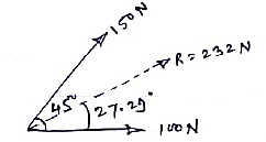 Ans:
Ans:
2> The sum of two forces is 270 N & their resultant is 180 N. If Resultant is Perpendicular to P, find the two forces P & Q.
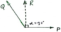 Given:
P + Q = 270 N
R = 180 N
α = 900
Soln: According to law of parallelogram,
Tanα = Q Sin θ / P + Q Cos θ Fig 14
Tan 90 = Q Sin θ / P + Q Cos θ
∞ = Q Sin θ / P + Q Cos θ
Here if P + Q Cos θ = 0, then only above term will become infinity.
Thus, P + Q Cosθ= 0
P = - Q Cos θ
-P = Q Cosθ . . . . (1)
Now, R2 = P2 + Q2 + 2PQ Cos θ
1802 = P2 + Q2 + 2P(-P) . . . from eqn (1)
1802 = P2 + Q2 + (-2P2)
1802 = P2 -2P2 + Q2
1802 = - P2 + Q2
1802 = Q2 - P2
1802 = (Q- P) (Q+ P)
= (Q- P) x 270
Q- P = 1802 / 270
Q- P = 120 . . . (ii)
& we know that
Q + P = 270 . . . (iii)
Solving (ii) & (iii) i.e. add eqn (ii) & (iii)
Q – P = 120
+ Q + P = 270
_______________
2Q + 0 = 390
2Q = 390
Q = 195 N &P = 75 N . . . Ans
Triangular law of forces
Triangular law of forces states that if there are two forces which are congregation or transient through a point then the third or enclosing side of a triangle is such that. So, this law explains, if two forces stand-in at a point is represented in scale and direction by the two adjacent sides of a triangle taken in order, then the closing side of the triangle taken in the reversed order represents the consequential of the forces in magnitude and direction.
The resultant of two forces acting at a point can also be found by using the Triangle Law of Forces.
If two forces acting at a point are represented in magnitude and direction by the two adjacent sides of a triangle taken in order, then the closing side of the triangle taken in the reversed order represents the resultant of the forces in magnitude and direction.
The triangle law of forces can also be stated as. If a body is in equilibrium under the action of three forces acting at a point, then the three forces can be completely represented by the three sides of a triangle taken in order.
Explanation
A body might be subjected to further than one force at a similar time. Suppose two equal forces are acting on the body at the same time, in the same way, the consequence is the sum of the two forces. But if the similar forces are accurately in reverse directions, they rescind with each other and therefore almost there is no effect on the body.
So, we learn that, if three forces, stand-in at a point, are represented in magnitude and way by the sides of a triangle, taken in order, they will be in equilibrium.
Forces P and Q act at an angle 0. In order to find the resultant of P and Q. One can apply the head to tail method, to construct the triangle.
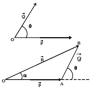
Fig 15
In Figure, OA and AB represent P and Q in magnitude and direction. The closing side OB of the triangle taken in the reversed order represents the resultant R of the forces P and Q. The magnitude and the direction of R can be found by using sine and cosine laws of triangles.
If P, Q, and R are the three forces acting at a point and they are represented by the three sides of a triangle then, P/OA = Q/AB = R/OB.
1.1.6 Polygon law of forces. Varignon’s theorem
If a number of forces acting simultaneously on a particle be represented in magnitude and direction by the sides of a polygon taken in order, their resultant may be represented in magnitude and direction by the closing side of the polygon taken in opposite order.
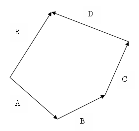
Where A, B, C and D are the forces and R = Resultant force
Varignon’s Theorem
It states that if number of forces is acting simultaneously on a body, the algebraic sum of moments of all the forces about any point is equal to moment of their resultant about same point.
Mathematically,
∑(F x d) = (R x X)
Where, F = All forces acting on a body
d = ḻlar distance
R = Resultant of all forces
X = ḻlar distance of Resultant force about a point where moment is taken.
Use:- This theorem is useful to calculate or find the position or location of Resultant of non-concurrent force system.
1.2.1 Analytical method, graphical method, Bow’s notation.
There are many ways in which forces can be manipulated. It is often easier to work with a large, complicated system of forces by reducing it to an ever-decreasing number of smaller problems. This is called the "resolution" of forces or force systems. This is one way to simplify what may otherwise seem to be an impossible system of forces acting on a body. Certain systems of forces are easier to resolve than others. Coplanar force systems have all the forces acting in in one plane. They may be concurrent, parallel, non-concurrent or non-parallel. All of these systems can be resolved by using graphic statics or algebra.
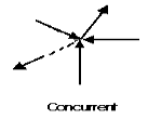
A concurrent coplanar force system is a system of two or more forces whose lines of action ALL intersect at a common point. However, all of the individual vectors might not acutally be in contact with the common point. These are the most simple force systems to resolve with any one of many graphical or algebraic options.
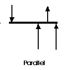
A parallel coplanar force system consists of two or more forces whose lines of action are ALL parallel. This is commonly the situation when simple beams are analysed under gravity loads. These can be solved graphically, but are combined most easily using algebraic methods.
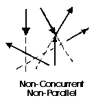
The last illustration is of a non-concurrent and non-parallel system. This consists of a number of vectors that do not meet at a single point and none of them are parallel. These systems are essentially a jumble of forces and take considerable care to resolve.
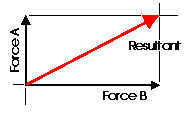
Almost any system of known forces can be resolved into a single force called a resultant force or simply a Resultant. The resultant is a representative force which has the same effect on the body as the group of forces it replaces. (A couple is an exception to this) It, as one single force, can represent any number of forces and is very useful when resolving multiple groups of forces. One can progressively resolve pairs or small groups of forces into resultants. Then another resultant of the resultants can be found and so on until all of the forces have been combined into one force. This is one way to save time with the tedious "bookkeeping" involved with a large number of individual forces. Resultants can be determined both graphically and algebraically It is important to note that for any given system of forces, there is only one resultant.

It is often convenient to decompose a single force into two distinct forces. These forces, when acting together, have the same external effect on a body as the original force. They are known as components. Finding the components of a force can be viewed as the converse of finding a resultant. There are an infinate number of components to any single force. And, the correct choice of the pair to represent a force depends upon the most convenient geometry. For simplicity, the most convenient is often the coordinate axis of a structure.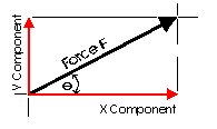
This diagram illustrates a pair of components that correspond with the X and Y axis. These are known as the rectangular components of a force. Rectangular components can be thought of as the two sides of a right angle which are at ninety degrees to each other. The resultant of these components is the hypotenuse of the triangle. The rectangular components for any force can be found with trigonometrically relationships: Fx = F cos theta, Fy = F sin theta (where theta is the angle). There are a few geometric relationships that seem common in general building practice in North America. These relationships relate to roof pitches, stair pitches, and common slopes or relationships between truss members. Some of these are triangles with sides of ratios of 3-4-5, 1-2-sqrt3, 1-1-sqrt2, 5-12-13 or 8-15-17. Committing the first three to memory will simplify the determination of vector magnitudes when resolving more difficult problems.
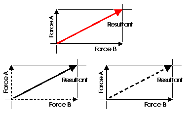
When forces are being represented as vectors, it is important to should show a clear distinction between a resultant and its components. The resultant could be shown with color or as a dashed line and the components as solid lines, or vice versa. NEVER represent the resultant in the same graphic way as its components.
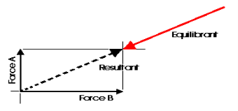
Any concurrent set of forces, not in equilibrium, can be put into a state of equilibrium by a single force. This force is called the Equilibrant. It is equal in magnitude, opposite in sense and co-linear with the resultant. When this force is added to the force system, the sum of all of the forces is equal to zero. A non-concurrent or a parallel force system can actually be in equilibrium with respect to all of the forces, but not be in equilibrium with respect to moments.
Graphic Statics and graphical methods of force resolution were developed before the turn of the century by Karl Culmann. They were the only methods of structural analysis for many years. These methods can help to develop an intuitive understanding of the action of the forces. Today, the Algebraic Method is considered to be more applicable to structural design. Despite this, graphical methods are a very easy way to get a quick answer for a structural design problem and can aid in the determination of structural form.
Graphic Methods of Coplanar Force Resolution
The Parallelogram of Forces Method is one of the graphical methods developed to find the resultant of a coplanar force system. Two or more concurrent forces can be replaced by a single resultant force that is statically equivalent to these forces.

The illustration shows two vectors and their resultant. The resultant force is shown as the dashed vector. In order to resolve these forces graphically, one must first extend the lines of action of two concurrent forces until they intersect. This intersection is known as the point of origin for the system. Both forces, as well as the resultant, must ALL act either away from or toward the point of origin.
The resultant can be represented graphically by the diagonal of the parallelogram formed by using the two force vectors to determine the length of the sides of the parallelogram. The magnitude of the resultant can be accurately measured as the scaled length of the diagonal. The resultant MUST go through the point of intersection of its components!!!
(Remember: graphical solutions depend upon the accuracy of the drawing. The length of each vector should be carefully scaled to equal the magnitude of the force).
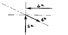
More than two non-parallel forces can be combined by successively eliminating one of the forces. Combine any two of the forces into their resultant by the parallelogram method. Combine this resultant with any of the remaining forces (or with the resultant of any of the remaining forces) until all of the forces are included. One must remember that the vectors can only be translated (or moved) along their lines of action. Two vectors (or Forces) cannot be combined (or resolved) until both of them are meeting head-to-head or tail-to-tail!
The resolution of this system is a single vector that has a magnitude of approximately 4k with a direction of up and to the left.
The Triangle of Forces Method is another graphical method developed to find the resultant of a coplanar force system. Since the opposite sides of a parallelogram are equal, a force triangle may also be found instead of using the parallelogram method. This method is quite useful because it can be successively applied to any number of concurrent forces.

Fig 17
To calculate the resultant of the force system shown above, move force A so that it's tail meets the head of force B. Now forces A and B form a "Head-to-Tail" arrangement. The resultant R is found by starting at the tail of B (the point of intersection of forces A and B) and drawing a vector which terminates at the head of the transposed A. Note that if force B had been transposed instead of force A, the resultant would have started from the tail of A and terminated at the head of force B. Again, this process could be repeated for any number of force vectors.
The resultant is described by the vector's magnitude and direction. These are determined by scaling the length and angle respectively. The accuracy of these values depends upon the accuracy of the graphics.
Bow’s notations
Bow's Notation is a labelling convention whereby the spaces in between any group of forces are labelled with a capital letter such that each force is then straddled by two letters. Since, within a Framed Structure all forces are assumed to be carried within the frame Members, it follows that all spaces within a frame are also labelled such that each Member is also straddled by two letters as shown.
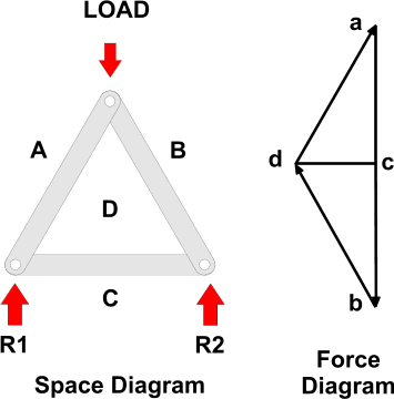
Fig 18
Labelling is carried out clockwise around the frame and each joint is then considered in turn, starting with the joint where there is sufficient data to draw a Force Diagram.
In the example shown:
- We can assume the Load is known and, working clockwise around the joint at the apex, the Vector can be drawn, scaled to its magnitude, and labelled with a direction arrow as creating a force a down to b - since we know the load acts downwards (note the convention to use lower case letters on Force Diagrams).
- The Lines of Action of the force within Members BD and DA are given by the frame drawing (or Space Diagram) and can be drawn through b and a respectively to intersect in d.
- It is a feature of Force Diagrams that the lines of force will follow each other around a Force Polygon and so, given the downwards direction of ab, it can be seen that, around the apex, the forces within both BD and DA are pointing upwards.
- Since all Members must stay still, or be in Equilibrium there must be equal and opposite forces at the lower ends of BD and DA (i.e. AD and DB) indicating that the these Members are Struts - which is what we would expect.
- This additional information can be used to determine other forces (e.g. The Reactions) by working clockwise around the two lower joints and adding dc for example, to the Force Diagram.
Reference:
1. Vector Mechanics for Engineers: Statics and Dynamics by Beer and Johnson, Tata McGraw Hill Education (India) Pvt. Ltd.
2. Engineering Mechanics by Irving H. Shames, Prentice Hall of India, New Delhi.
3. Engineering Mechanics Statics and Dynamics by Ferdinand Singer, Harper& Row Publications.
4. Engineering Mechanics Statics, Vol.1, SI Version, 7th Edition – J. L. Meriam, L. G. Kraige, Wiley India Pvt. Ltd., New Delhi.
5. Engineering Mechanics Dynamics, SI Version, 7th Edition – J. L. Meriam, L. G. Kraige, Wiley India Pvt. Ltd., and New Delhi.