Unit-2
Equilibrium of Rigid Bodies
2.1.1 Equilibrium of co-planar forces
Coplanar concurrent forces
The sum of all forces in the x-direction or horizontal is zero.
ΣFx=0 or ΣFH=0
The sum of all forces in the y-direction or vertical is zero.
ΣFy=0 or ΣFV=0
Important Points for Equilibrium Forces
- Two forces are in equilibrium if they are equal and oppositely directed.
- Three coplanar forces in equilibrium are concurrent.
- Three or more concurrent forces in equilibrium form a close polygon when connected in head-to-tail manner.
Equilibrium of Coplanar concurrent forces
Concurrent means that the forces intersect through a single point. If forces are concurrent, we can add them together as vectors to get the resultant.
If the body is not accelerating, it must be in equilibrium, so that means the resultant is zero
For concurrent forces, the body is a point. So for concurrent forces in equilibrium, the forces should all add up to give zero.
If a body is not accelerating is in equilibrium, so resultant of all forces = 0.
A typical concurrent force situation is a lifting eye. The pulling forces in any cables must pass through the centre of the eye. If there is only one eyebolt (correctly positioned over the centre of gravity) and the load is suspended, the bolt force must pass through the same centre. Hence all forces pass through one point (the centre of the eye), so we have concurrent equilibrium.
Coplanar non-concurrent forces
It is defined as the forces which lies in the line of activity but do not intersect or forms a parallel at a common point. The forces are the general system of forces.
Show the non-concurrent, non-parallel systems in figure (1).
Coplanar = within the same plane.
Concurrent = passing through the same point.
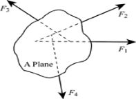
Fig 1
In figure (1 ), there are four forces; F1, F2, F3 and F4 respectively. These forces act on a single A plane.
Consider an example for non-concurrent, non-parallel systems. A man is standing on the ladder which is resting against a wall. Here, the forces on the ladder do not meet at a common point but it lies on a single plane which is the wall.
The resultant of non-concurrent, non-parallel systems is obtained by the principles of equilibrium. In non-concurrent force system, consider three equilibrium conditions; force equilibriums in x-direction and y&-direction, and moment equilibrium by the sum of moments about point O.
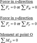
The pair of force system is solved graphically along with parallelogram or triangle law. After calculating the pair of forces, calculate the resultant of the forces and combine it to determine the new resultant.
Equilibrium of Coplanar non-concurrent forces
There are three equilibrium conditions that can be used for non-concurrent, non-parallel force system.
The sum of all forces in the x-direction or horizontal is zero.
ΣFx=0 or ΣFH=0
The sum of all forces in the y-direction or vertical is zero.
ΣFy=0 or ΣFV=0
The sum of moment at any point O is zero.
ΣMO=0
The three equilibrium conditions can solved up to three unknowns in the system. If the system involves more than three unknowns, it is called indeterminate.
Key points
1) Coplanar = within the same plane.
2) Concurrent = passing through the same point.
3) If a body is not accelerating is in equilibrium, so resultant of all forces = 0.
2.1.2 Analytical and graphical conditions of equilibrium
There are many ways in which forces can be manipulated. It is often easier to work with a large, complicated system of forces by reducing it to an ever decreasing number of smaller problems. This is called the "resolution" of forces or force systems. This is one way to simplify what may otherwise seem to be an impossible system of forces acting on a body. Certain systems of forces are easier to resolve than others. Coplanar force systems have all the forces acting in in one plane. They may be concurrent, parallel, non-concurrent or non-parallel. All of these systems can be resolved by using graphic statics or algebra.
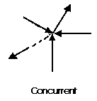
Fig 2
A concurrent coplanar force system is a system of two or more forces whose lines of action ALL intersect at a common point. However, all of the individual vectors might not actually be in contact with the common point. These are the most simple force systems to resolve with any one of many graphical or algebraic options.
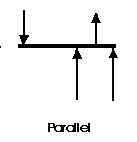
Fig 3
A parallel coplanar force system consists of two or more forces whose lines of action are ALL parallel. This is commonly the situation when simple beams are analyses under gravity loads. These can be solved graphically, but are combined most easily using algebraic methods.
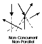
Fig 4
The last illustration is of a non-concurrent and non-parallel system. This consists of a number of vectors that do not meet at a single point and none of them are parallel. These systems are essentially a jumble of forces and take considerable care to resolve.
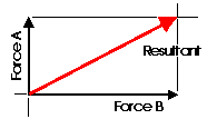
Fig 5
Almost any system of known forces can be resolved into a single force called a resultant force or simply a Resultant. The resultant is a representative force which has the same effect on the body as the group of forces it replaces. (A couple is an exception to this) It, as one single force, can represent any number of forces and is very useful when resolving multiple groups of forces. One can progressively resolve pairs or small groups of forces into resultants. Then another resultant of the resultants can be found and so on until all of the forces have been combined into one force. This is one way to save time with the tedious "bookkeeping" involved with a large number of individual forces. Resultants can be determined both graphically and algebraically It is important to note that for any given system of forces, there is only one resultant.

Fig 6
It is often convenient to decompose a single force into two distinct forces. These forces, when acting together, have the same external effect on a body as the original force. They are known as components. Finding the components of a force can be viewed as the converse of finding a resultant. There are an infinite number of components to any single force. And, the correct choice of the pair to represent a force depends upon the most convenient geometry. For simplicity, the most convenient is often the coordinate axis of a structure.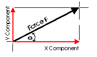
This diagram illustrates a pair of components that correspond with the X and Y axis. These are known as the rectangular components of a force. Rectangular components can be thought of as the two sides of a right angle which are at ninety degrees to each other. The resultant of these components is the hypotenuse of the triangle. The rectangular components for any force can be found with trigonometrically relationships: Fx = F cos theta, Fy = F sin theta (where theta is the angle). There are a few geometric relationships that seem common in general building practice in North America. These relationships relate to roof pitches, stair pitches, and common slopes or relationships between truss members. Some of these are triangles with sides of ratios of 3-4-5, 1-2-sqrt3, 1-1-sqrt2, 5-12-13 or 8-15-17. Committing the first three to memory will simplify the determination of vector magnitudes when resolving more difficult problems.
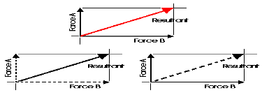
Fig 7
When forces are being represented as vectors, it is important to should show a clear distinction between a resultant and its components. The resultant could be shown with color or as a dashed line and the components as solid lines, or vice versa. NEVER represent the resultant in the same graphic way as its components.
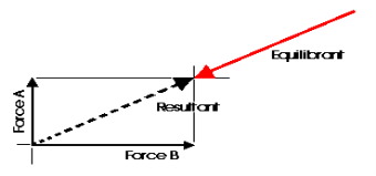
Any concurrent set of forces, not in equilibrium, can be put into a state of equilibrium by a single force. This force is called the Equilibrant. It is equal in magnitude, opposite in sense and co-linear with the resultant. When this force is added to the force system, the sum of all of the forces is equal to zero. A non-concurrent or a parallel force system can actually be in equilibrium with respect to all of the forces, but not be in equilibrium with respect to moments.
Graphic Statics and graphical methods of force resolution were developed before the turn of the century by Karl Culmann. They were the only methods of structural analysis for many years. These methods can help to develop an intuitive understanding of the action of the forces. Today, the Algebraic Method is considered to be more applicable to structural design. Despite this, graphical methods are a very easy way to get a quick answer for a structural design problem and can aid in the determination of structural form.
Graphic Methods of Coplanar Force Resolution
The Parallelogram of Forces Method is one of the graphical methods developed to find the resultant of a coplanar force system. Two or more concurrent forces can be replaced by a single resultant force that is statically equivalent to these forces.

Fig 8
The illustration shows two vectors and their resultant. The resultant force is shown as the dashed vector. In order to resolve these forces graphically, one must first extend the lines of action of two concurrent forces until they intersect. This intersection is known as the point of origin for the system. Both forces, as well as the resultant, must ALL act either away from or toward the point of origin.
The resultant can be represented graphically by the diagonal of the parallelogram formed by using the two force vectors to determine the length of the sides of the parallelogram. The magnitude of the resultant can be accurately measured as the scaled length of the diagonal. The resultant MUST go through the point of intersection of its components!!!
(Remember: graphical solutions depend upon the accuracy of the drawing. The length of each vector should be carefully scaled to equal the magnitude of the force).
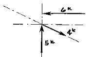
More than two non-parallel forces can be combined by successively eliminating one of the forces. Combine any two of the forces into their resultant by the parallelogram method. Combine this resultant with any of the remaining forces (or with the resultant of any of the remaining forces) until all of the forces are included. One must remember that the vectors can only be translated (or moved) along their lines of action. Two vectors (or Forces) cannot be combined (or resolved) until both of them are meeting head-to-head or tail-to-tail!
The resolution of this system is a single vector that has a magnitude of approximately 4k with a direction of up and to the left.
The Triangle of Forces Method is another graphical method developed to find the resultant of a coplanar force system. Since the opposite sides of a parallelogram are equal, a force triangle may also be found instead of using the parallelogram method. This method is quite useful because it can be successively applied to any number of concurrent forces.

Fig 9
To calculate the resultant of the force system shown above, move force A so that it's tail meets the head of force B. Now forces A and B form a "Head-to-Tail" arrangement. The resultant R is found by starting at the tail of B (the point of intersection of forces A and B) and drawing a vector which terminates at the head of the transposed A. Note that if force B had been transposed instead of force A, the resultant would have started from the tail of A and terminated at the head of force B. Again, this process could be repeated for any number of force vectors.
The resultant is described by the vector's magnitude and direction. These are determined by scaling the length and angle respectively. The accuracy of these values depends upon the accuracy of the graphics.
2.1.3 Different type of supports
- Types of Support
- Roller Support: -
 Roller support is show in two ways as shown:
 A free body diagram of roller support is shown in figure given below
- Roller support offers only one reaction; which is always perpendicular to the base or plane of roller.
- All the steel trusses of the bridges have one of their ends supported on roller.
- Main advantages of the support are that beam can easily move towards left or right due to expansion & contraction.
2. Hinge support

- In this case, end of the beam is hinged to the support as shown in figure above.
- This type of support offers two reactions, one is parallel to base and perpendicular to the base
- All the steel trusses of the bridges have one of their end roller supported & other end is hinged
- Main advantage of this support is that beam remains stable.
- If both ends of the beam are roller supported, then beam can not be stable. Thus, one support of beam is made roller supported and other is hinged.
3. Internal Hinge: -
 When two members are connected by the hinge then this type of support is called as internal Hinge.


Internal Hinge
Reactions at internal Hinge
4. Fixed support: -
Fixed support offers three reactions as shown in figure below.
- Reaction in horizontal direction.
- Reaction in vertical direction.
- Moment (fixing moment)

Fixed Support
2.1.4 Free body diagrams, Lami’s theorem
Free body diagram: -
If a body is shown with all external forces acting on it so that the body is in equilibrium, such diagram is called as free body diagram.
To draw the free body diagram, we have to remove all the restrictions like wall, floor, hinge, any other support and replace them by reactions which these support extents on the body.
Ex – 1) Draw FBD of a bar supported and loaded as shown below.

Fig 10
2) Draw FBD of sphere supported as shown below.

Fig 11
- Equilibrium
- A body is said to be in equilibrium if the resultant of all forces acting on it is zero.
- When the resultant of all the forces acting on the particle is zero, then, the particle is in equilibrium.
- If the resultant force acting on a particle is zero (or if particle is in equilibrium state) the, particle will remain at rest condition if it is originally at rest; or particle will move with constant speed in a straight line if it is originally in motion.
Condition for Equilibrium: R = 0 {  }
}
∑M = 0
Lami’s Theorem: - (Body is subjected to three forces)
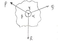 If three coplanar concurrent forces are in equilibrium then, the ratio of magnitude of any force to the sine of angle between the other two is constant.
Fig 12
According to Lami’s Theorem:
Lami’s theorem can also be written as: If three coplanar concurrent forces acting at a point are in equilibrium, each force is proportional to the sine of angle between other two.
2.2.1Types of friction, limiting friction
Types of friction
Friction is the force that opposes motion between any surfaces that are in contact. There are four types of friction: static, sliding, rolling, and fluid friction. Static, sliding, and rolling friction occur between solid surfaces. Fluid friction occurs in liquids and gases. All four types of friction are described below.
Static Friction
Static friction acts on objects when they are resting on a surface. For example, if you are hiking in the woods, there is static friction between your shoes and the trail each time you put down your foot (see Figure below). Without this static friction, your feet would slip out from under you, making it difficult to walk. In fact, that's exactly what happens if you try to walk on ice. That's because ice is very slippery and offers very little friction.
Sliding Friction
Sliding friction is friction that acts on objects when they are sliding over a surface. Sliding friction is weaker than static friction. That's why it's easier to slide a piece of furniture over the floor after you start it moving than it is to get it moving in the first place. Sliding friction can be useful. For example, you use sliding friction when you write with a pencil. The pencil “lead” slides easily over the paper, but there's just enough friction between the pencil and paper to leave a mark.
Rolling Friction
Rolling friction is friction that acts on objects when they are rolling over a surface. Rolling friction is much weaker than sliding friction or static friction. This explains why most forms of ground transportation use wheels, including bicycles, cars, 4-wheelers, roller skates, scooters, and skateboards. Ball bearings are another use of rolling friction. You can see what they look like in the Figure below. They let parts of a wheel or other machine roll rather than slide over on another.
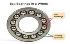
Fig 13
The ball bearings in this wheel reduce friction between the inner and outer cylinders when they turn.[Figure 13]
Fluid Friction
Fluid friction is friction that acts on objects that are moving through a fluid. A fluid is a substance that can flow and take the shape of its container. Fluids include liquids and gases. If you've ever tried to push your open hand through the water in a tub or pool, then you've experienced fluid friction. You can feel the resistance of the water against your hand. Look at the skydiver in the Figure below. He's falling toward Earth with a parachute. Resistance of the air against the parachute slows his descent. The faster or larger a moving object is, the greater is the fluid friction resisting its motion. That's why there is greater air resistance against the parachute than the skydiver's body.
Limiting friction
It is the highest value of static friction which comes into play when an object is just about to slide over the surface of a different object. For an exerted external force greater than the limiting friction, the body begins to move.
Once the motion has started, static friction cannot be considered. A new type of friction termed as kinetic friction comes into play.
Laws of Limiting Friction:
- The direction of limiting frictional force is always contrary to the direction of motion.
- Limiting friction acts tangentially to the two surfaces interacting.
- The magnitude of limiting friction is proportional to the normal reaction amidst the two surfaces.
- The limiting friction hinges upon the material, the nature of the surfaces interacting, and their evenness.
- So long as the normal reaction is the same, the magnitude of limiting friction is free of the shape or the area of the surfaces in contact, for any two given surfaces.
2.2.2 Laws of Friction, Static and Dynamic friction
Laws of Static Friction:
Following are the laws of static friction:
1. The force of friction always acts in direction which is opposite to motion of body.
2. The magnitude of force of friction is equal to the force acting on the body externally.
3. There is constant ratio between limiting frictional force and the normal reaction forces. Mathematically:
(F/R) = Constant
Where F = Limiting friction, and R = Normal reaction.
4. The force of friction does not depend on the area of contact between the two surfaces.
5. There is dependency of frictional force on roughness of the surfaces.
- Laws of Kinematic or Dynamic Friction:
Following are the laws of kinetic or dynamic friction:
1. The force of friction always act such that it opposes the motion of body.
2. There is a constant ratio between kinetic motion and normal reaction. But this ratio is slightly less when it comes to limiting friction.
3. For medium speeds, the force due to friction stays constant. But it decreases somewhat when the speed increases.
e.g. 1: The uniform crate shown in Fig 14. Below has a mass of 20 kg. If a force P = 80 N is applied to the crate, determine if it remains in equilibrium. The coefficient of static friction is  = 0.3.
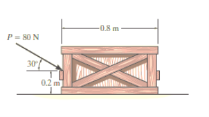
Fig 14
Solution:
The first step is free-body diagram i.e.
Free-Body Diagram. As shown in Fig 15. Diagram below, the resultant normal force NC acts at a distance of x from the Centre line of crate for countering the tilting effect caused by P. Hence, there are three unknowns, F, NC and x, which can be solved by equations of equilibrium.
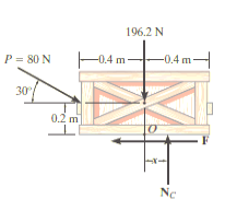
Fig 15
Equations of equilibrium:
Σ Fx = 0
80 cos 30° N - F = 0
Σ Fy = 0
-80 sin 30° N + NC - 196.2 N = 0
Σ M = 0
80 sin 30° N10.4 m2 - 80 cos 30° N10.2 m2 + NC (x) = 0
Thus, solving the above equations, we get,
F = 69.3 N
NC = 236 N
x = -0.00908 m = -9.08 mm
As value of x is negative, hence it acts to left of centre line of the crate. There will be no tipping since x < 0.4 m. Fmax =  Nc = 0.3(236 N) = 70.8 N. Since F that we got is 69.3 N < 70.8 N, the crate will not slip.
2.2.3 Inclined planes, ladders
Wedge friction
A wedge is a piece of metal or wood which is usually of a triangular or trapezoidal in cross-section. It is used for either lifting loads through small vertical distances or used for slight adjustments in the position of a body i.e., for tightening fits or keys for shafts.
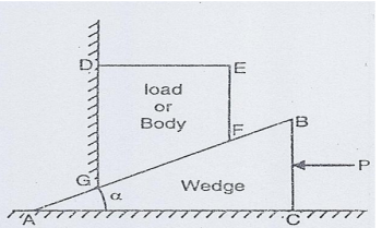
When lifting a heavy load the wedge is placed below the load and a horizontal force P is applied as shown in Fig. 16. If the force P is just sufficient to lift the load, the wedge will move towards left and load will move up. When the wedge moves towards left, the sliding of the surfaces AC and AB will take place. At the same time load moves up and sliding of the load takes place along GD. Thus for the wedge and load shown in Fig.16 sliding takes place along surface AB, AC and DG. Hence there will be three normal reactions at AB, AC and DG.
The problems on wedges are generally the problems of equilibrium on inclined planes. Therefore, these problems are solved by equilibrium method or by applying Lami’s Theorem
.
Fig 16
Equilibrium Method In this method, the equilibrium of the load (or the body placed on the wedge) and the equilibrium of the wedge are considered.
Equilibrium of Wedge
Consider the equilibrium of the wedge. The forces acting on the wedge are shown in Fig. 14. They are:
(i) The force P applied horizontally on face BC.
(ii) Reaction R1 on the face AC (The reaction R1 is the resultant of the normal reaction N1 on the rubbing face AB and force of friction on surface AC). The reaction R1 will be inclined at an angle θ1 (when θ1 is angle of friction) with the normal.
(iii) Reaction R2 on the face AB (The reaction R2 is the resultant of normal reaction N2 on the rubbing face AB and force of friction on surface AB). The reaction R2 will be inclined at an angle Φ2 with the normal.
When the force P is applied on the wedge, the surface CA will be moving towards left and hence force of friction on this surface will be acting towards right. Similarly, the force of friction on face AB will be acting from A to B. These forces are shown in Fig. 17.
Resolving the forces horizontally, we get
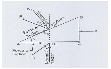
Fig 17 Equilibrium of wedge
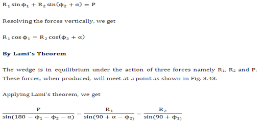
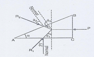
Fig 18
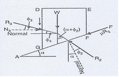
Fig 19
Equilibrium of body placed on the Wedge
The forces acting on the body are shown in Fig.17. They are:
(i) The weight W on the body.
(ii)Reaction R3 on the face GD. (The reaction R3 is the resultant of the normal reaction N3 on the rubbing face GD and force of friction on surface GD).
(iii)Reaction R3 on the face GF (The reaction R2 is the resultant of the normal reaction N2 on the rubbing face GF and force of friction on surface GF).
These forces are shown in Fig. 17.
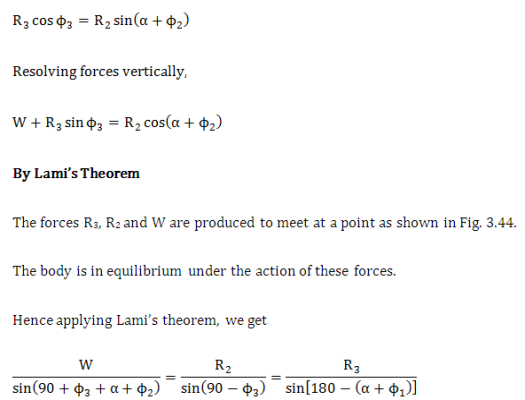
Resolving the forces R2, R3 and W horizontally, we get
Ladder friction
If a ladder is placed against a rough horizontal floor and a vertical wall (smooth or roughly) then ladder is subjected to non-concurrent force system.

Fig 20
Fig 20 A rough slope inclined at theta to the horizontal with a block of mass m resting on it. The block is in equilibrium so all of the forces acting on it sum to zero as shown by the vector triangle
Friction acts along the plane where the two surfaces are touching. For a block on a slope, as shown here, the friction force acts in the plane of the slope. In this case the block is stationary and so the frictional force acts to prevent it sliding down the slope, so the frictional force acts up the slope.
If the block is in equilibrium then the forces on it sum to zero. Resolving perpendicular to the slope gives N= mgcosθ. This means that the maximum frictional force is F=μmgcosθ where μ is the coefficient of friction between the block and the slope.
2.2.4 Support reactions of statically determinate beams with point loads, inclined loads, uniformly distributed load, uniformly varying loads and couples.
Types of loads on the Beam
- Point load
Load acting at a single point on the beam is known as point load. Its unit is N or kN

2. Uniformly Distributed load (UDL) or Rectangular Load:
A load which is spread over the beam or part of the beam uniformly is known as UDL

Conversion of UDL or Rectangular load into point load
= Intensity of UDL × distance
= w. l. ------------- N
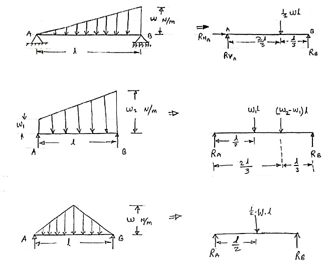
3. Uniformly varying load or Triangular load:
A load whose intensity is linearly varying between the two points on the beam is known as UVL. If an intensity of the load at one end is zero and at other ends is maximum then it is called as uniformly varying load or triangular load.
Following figures shows different types of UVL
- To convert UVL into point load, calculate the area of uniformly varying load.
- For location of point load find x coordinate of centroid of the UVL area.
3.

Fig 21
Que 1. Find the support reactions of given beam for loading as shown below.
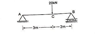
 Draw FBD of given beam & applying conditions of equilibrium
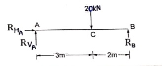
∑fx = 0
RHA = 0
∑fxy = 0
RVA – 20 + RB = 0
RVA + RB = 20 -----(1)
Taking moments at A
∑MA = 0
(20 × 3) – (RB × 5) = 0
60 – 5RB

RB = 12 kN  put in equation (1)
 RVA + 12 = 20
 RVA = 20-12
RVA = 8 kN 
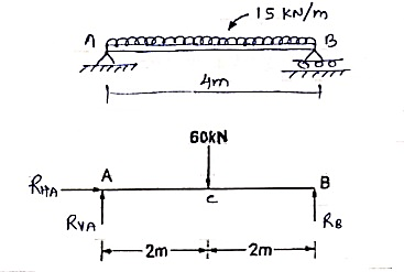 Que. 2 Find support reaction for given beam
 Resolving forces horizontally
∑fx = 0
RHA = 0
Resolving forces vertically
∑fy = 0
RVA – 60 + RB = 0
RVA + RB = 60 ----(1)
Taking moment at A
∑MA = 0
(60 × 2) – (RB × 4 ) = 0
 120 – 4RB = 0
 RB =
RB = 
RB = 30 kN 
Question 3. Find the support reactions of a given loading for Beam.
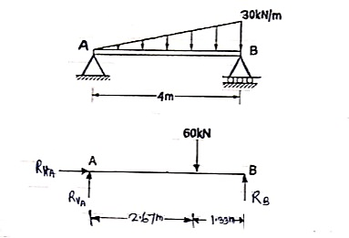
 Resolving forces horizontally
∑fX = 0
RHA = 0
Resolving forces vertically
∑fY = 0
RVA – 60 + RB = 0
RVA + RB = 60 ----------------- (1)
Taking moments at A
∑ MA = 0
(RVA × 0) + (60 × 2.67) – 4RB = 0
160.2 – 4RB = 0
 put in equation (1)
We get
RVA + 40 = 60
RVA = 60 – 40
RVA = 20 kN 
Forces in space
- The force system which is acting in different planes is called as non – coplanar force sys. Or space force.
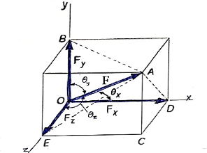 If a force is defined by three co-ordinates axis then it is called as space force.
Fig 22
Rectangular components of force in space: -
Let us consider the force F which is acting along the diagonal OA as shown above and making angles ØX, ØY, ØZ, with x,y,z axis respectively.
The above forces F in a three-dimensional space can be resolved into rectangular components FX, FY, FZ.
Then
Fx = F cosØX
FY = F cosØy
FZ = F cosØZ

Here cosØX, cosØy, cosØZ are the cosines of ØX, Øy, ØZ and are known as directions cosine of force F.
The force vector  can be expressed as ;
 = (FX i + FY j + FZ k)
 = (FcosØX i + FcosØy j + FcosØZ k)
 = F (cosØX i + cosØy j + cosØZ k)
 = F.
= F.
In above equation,
F = magnitude of force
 = unit vector along the direction of force.
 = (cosØX i + cosØy j + cosØZ k)
Here, cos2 ØX + cos2 ØY + cos2 ØZ = 1
Direction cosines can be found only by,
CosØX = 
CosØY = 
CosØZ = 
- When force F is defined in three dimensional space by using two points on its line of action, then rectangular components can be obtained as follows.
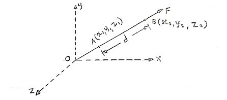
Fig 23
Consider force F acting at point O. Let A(x1,y1,z1)& B(x2,y2,z2) are the two points on the line of action of force F.
Let distance between two points (on the line of action of force) A & B is ‘d’.
Now
Vector  dx i + dy j + dz k
Magnitude of AB = d = 
We know that vector = magnitude × unit vector along AB
 AB
AB
 AB =
AB = 
 AB = (dx I + dy j + dz k) ×
We know that force  = magnitude x unit vector along line of action
 = F ×
= F ×  AB
AB
 =
=  (dx i + dy j + dz k)
 =
= 
From above equation we can have three components of force,
Fx = 
Fy = 
FZ = 
- Unit vector along direction of force
 AB =
AB = 
eAB = 
eAB =  unit vector
Position vector
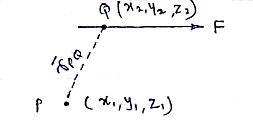
- Consider force F passing through point Q (x2, y2, z2)
- Let P (x1, y1, z1) is point away from line of action.
Then,
 PQ = position vector of P w.r.t. Q
= dx I + dy j + dz k
 PQ = (x2-x1)i + (y2 – y1)j + (z2-z1)k
r = 
Resultant of several forces in space:-
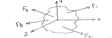
Fig 24
Consider a body on which forces F1, F2 , F3 , F4 are acting as shown in figure.
R = Rx i + Ry j + Rz k
Rx = Resultant in x direction = ∑Fx = Fx1 + Fx2 + Fx3 + Fx4
Ry = Resultant in y direction = ∑Fy = Fy1 + Fy2 + Fy3 + Fy4
Rz = Resultant in z direction = ∑Fz = Fz1 + Fz2 + Fz3 + Fz4
R = 
Direction of resultant w.r.t. x,y,z axis is


- Moment of force in space about point
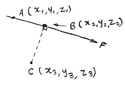
Fig 25
Consider a force  = Fx i + Fy j + Fz k is passing through two points A(x1, y1, z1) & B(x2, y2, z2) as shown.
Then moment of this force about point C(x3, y3, z3) will be
Mc =  CA ×
CA × 
Mc =| |
|
Here, [ rx = (x1 – x3), ry = (y1 – y3) & rz = (z1 – z3)]
Mx = (ryFZ - rZFZ)
My = (rZFX - rXFZ)
Mz = (rXFY - rYFX)
Mc = 
Reference
1. Engineering Mechanics by S. P. Timoshenko and D. H. Young, McGraw- Hill publication
2. Engineering Mechanics by J. L. Meriam and Craige, John Willey
3. Engineering Mechanics by F L Singer, Harper and Rowe publication
4. Engineering Mechanics by A. P. Boresi and R. J. Schmidt, Brooks/Cole Publication