Unit-4
Centre of Gravity and Moment of Inertia
Centre of Gravity
One way to look at gravity is to look at it as a force that pulls things downward more precisely towards the centre of the Earth. But it doesn’t always work like that! Sometimes gravity causes things to topple and turn over, especially if they are high up and unbalanced. No one understands this better than tightrope walkers. While tiptoeing on the high wire, they often wobble from side to side to entertain us, yet they hardly ever fall. Instinctively they understand the physics of forces and manage to stay firmly on the rope. If you, like them, understand a simple concept known as the centre of gravity, you consider balancing a child’s play!
Centre of gravity is a theoretical point in the body where the total weight of the body is thought to be concentrated. It is important to know the centre of gravity because it predicts the behaviour of a moving body when acted on by gravity and it is also useful in designing static structures such as buildings and bridges.
In a uniform gravitational field, the centre of gravity is identical to the centre of mass. Yet, the two points do not always coincide. For the Moon, the centre of mass is very close to its geometric centre. However, its centre of gravity is slightly towards the Earth due to the stronger gravitational force on the Moon’s near side.
In a symmetrically shaped object formed of homogenous material, the centre of gravity may match with the geometric centre of the body. However, an asymmetrical object composed of a variety of materials with different masses is likely to have its centre of gravity located at some distance away from its geometric centre. In hollow bodies or irregularly shaped bodies, the centre of gravity lies at a point external to the physical material
Centroid of a composite area
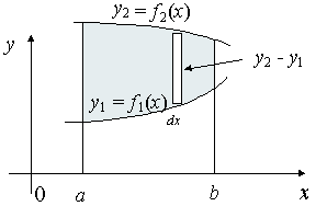
Fig 7
We extend the simple case given above. The "typical" rectangle indicated has width Δx and height y2 − y1, so the total moments in the x-direction over the total area is given by:

For the y coordinate, we have 2 different ways we can go about it.
Method 1: We take moments about the y-axis and so we'll need to re-express the expressions x2 and x1 as functions of y.

Method 2: We can also keep everything in terms of x by extending the "Alternate Method" given above:

Centroids of Composite sections (1D, 2D)
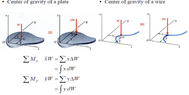
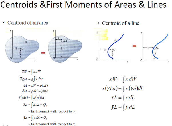
First Moments of Areas and Lines
•An area is symmetric with respect to an axis BB’ if for every point P there exists a point P’ such that PP’ is perpendicular to BB’ and is divided into two equal parts by BB’.
•The first moment of an area with respect to a line of symmetry is zero.
•If an area possesses a line of symmetry, its centroid lies on that axis
•If an area possesses two lines of symmetry, its centroid lies at their intersection.
•An area is symmetric with respect to a center O if for every element dA at (x,y) there exists an area dA’ of equal area at (-x,-y).
•The centroid of the area coincides with the center of symmetry.
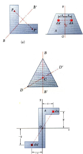
Fig 8
Key points
Centroid formula:


Centroid
In Geometry, the centroid is an important concept related to a triangle. A triangle is a three-sided bounded figure with three interior angles. Based on the sides and angles, a triangle can be classified into different types such as
- Scalene triangle
- Isosceles triangle
- Equilateral triangle
- Acute-angled triangle
- Obtuse-angled triangle
- Right-angled triangle
Centroid Definition
The centroid is the centre point of the object. The point in which the three medians of the triangle intersect is known as the centroid of a triangle. It is also defined as the point of intersection of all the three medians. The median is a line that joins the midpoint of a side and the opposite vertex of the triangle. The centroid of the triangle separates the median in the ratio of 2: 1. It can be found by taking the average of x- coordinate points and y-coordinate points of all the vertices of the triangle.
Centroid Theorem
The centroid theorem states that the centroid of the triangle is at 2/3 of the distance from the vertex to the mid-point of the sides.
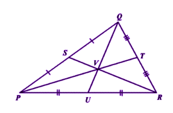
Fig 1
Suppose PQR is a triangle having a centroid V. S, T and U are the midpoints of the sides of the triangle PQ, QR and PR, respectively. Hence as per the theorem;
QV = 2/3 QU,
PV = 2/3 PT and RV = 2/3 RS
Centroid of a Right-Angle Triangle
The centroid of a right-angle triangle is the point of intersection of three medians, drawn from the vertices of the triangle to the midpoint of the opposite sides.
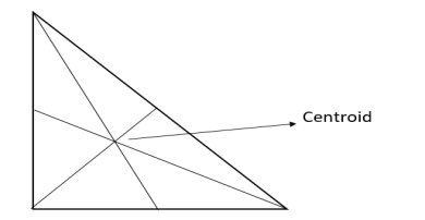
Fig 2
Centroid of a Square
The point where the diagonals of the square intersect each other is the centroid of the square. As we all know, the square has all its sides equal. Hence it is easy to locate the centroid in it. See the below figure, where O is the centroid of the square.
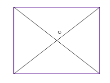
Fig 3
Properties of centroid
The properties of the centroid are as follows:
- The centroid is the centre of the object.
- It is the centre of gravity.
- It should always lie inside the object.
- It is the point of concurrency of the medians.
Centroid Formula
Let’s consider a triangle. If the three vertices of the triangle are A(x1, y1), B(x2, y2), C(x3, y3), then the centroid of a triangle can be calculated by taking the average of X and Y coordinate points of all three vertices. Therefore, the centroid of a triangle can be written as:
Centroid of a triangle = ((x1+x2+x3)/3, (y1+y2+y3)/3)
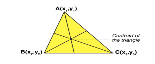
Fig 4
Centroid Formula for Different Shapes
Here, the list of centroid formula is given for different geometrical shapes.
Shapes | Figure | x̄ | ȳ | Area |
Triangular area | 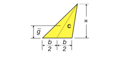 | – | h/3 | Bh/2 |
Quarter-circular area | 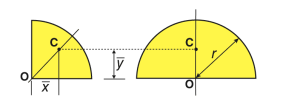 | 4r/3π | 4r/3π | πr2/4 |
Semi-circular area | 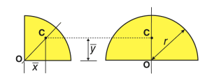 | 0 | 4r/3π | πr2/2 |
Quarter-elliptical area | 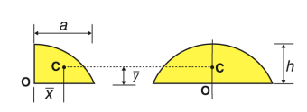 | 4a/3π | 4b/3π | πab/4 |
Semi elliptical area | 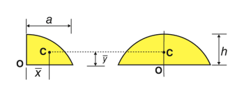 | 0 | 4b/3π | πab/2 |
Semi parabolic area | 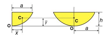 | 3a/8 | 3h/5 | 2ah/3 |
Parabolic area | 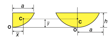 | 0 | 3h/5 | 4ah/3 |
Parabolic spandrel | 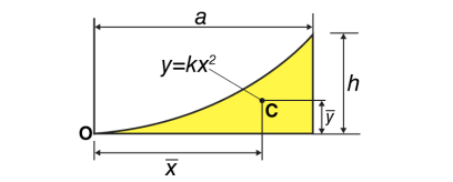 | 3a/4 | 3h/10 | Ah/3 |
Key points
1) Centroid of a triangle = ((x1+x2+x3)/3, (y1+y2+y3)/3)
2) The centroid is the centre point of the object. The point in which the three medians of the triangle intersect is known as the centroid of a triangle
Centroid of composite sections
Taking the simple case first, we aim to find the centroid for the area defined by a function f(x), and the vertical lines x = a and x = b as indicated in the following figure.
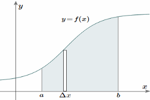
Fig 5
To find the centroid, we use the same basic idea that we were using for the straight-sided case above. The "typical" rectangle indicated is x units from the y-axis, and it has width Δx (which becomes dx when we integrate) and height y = f(x)
Generalizing from the above rectangular areas case, we multiply these 3 values x, f(x) and Δx, which will give us the area of each thin rectangle times its distance from the x-axis), then add them. If we do this for infinitesimally small strips, we get the x-coordinates of the centroid using the total moments in the x-direction, given by:

And, considering the moments in the y-direction about the x-axis and re-expressing the function in terms of y, we have:

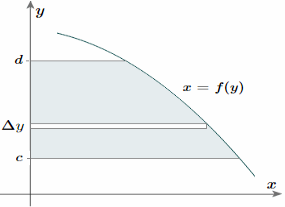
Fig 6
Notice this time the integration is with respect to y, and the distance of the "typical" rectangle from the x-axis is y units. Also note the lower and upper limits of the integral are c and d, which are on the y-axis.
Of course, there may be rectangular portions we need to consider separately. (I've used a different curve for the y case for simplification.)
Alternate method: Depending on the function, it may be easier to use the following alternative formula for the y-coordinate, which is derived from considering moments in the x-direction (Note the "dx" in the integral, and the upper and lower limits are along the x-axis for this alternate method).
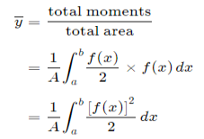
This is true since for our thin strip (width dx) the centroid will be half the distance from the top to the bottom of the strip. Another advantage of this second formula is there is no need to re-express the function in terms of y.
4.4.1 Definition, moment of inertia of plane, sections from first principles
Moment of inertia in physics quantitative measure of the rotational inertia of a body i.e the opposition that the body exhibits to having its speed of rotation about an axis altered by the application of a torque (turning force) The axis may be internal or external and may or may not be fixed. The moment of inertia (I), however, is always specified with respect to that axis and is defined as the sum of the products obtained by multiplying the mass of each particle of matter in a given body by the square of its distance from the axis. In calculating angular momentum for a rigid body, the moment of inertia is analogous to mass in linear momentum. For linear momentum, the momentum p is equal to the mass m times the velocity v; whereas for angular momentum, the angular momentum L is equal to the moment of inertia I times the angular velocity ω.
The figure shows two steel balls that are welded to a rod AB that is attached to a bar OQ at C. Neglecting the mass of AB and assuming that all particles of the mass m of each ball are concentrated at a distance r from OQ, the moment of inertia is given by I = 2mr2.

Fig 9
The unit of moment of inertia is a composite unit of measure. In the International System (SI), m is expressed in kilograms and r in metres, with I (moment of inertia) having the dimension kilogram-metre square. In the U.S. Customary system, m is in slugs (1 slug = 32.2 pounds) and r in feet, with I expressed in terms of slug-foot square.
The moment of inertia of anybody having a shape that can be described by a mathematical formula is commonly calculated by the integral calculus. The moment of inertia of the disk in the figure about OQ could be approximated by cutting it into a number of thin concentric rings, finding their masses, multiplying the masses by the squares of their distances from OQ, and adding up these products. Using the integral calculus, the summation process is carried out automatically; the answer is
I = (mR2)/2.
For a body with a mathematically indescribable shape, the moment of inertia can be obtained by experiment. One of the experimental procedures employs the relation between the period (time) of oscillation of a torsion pendulum and the moment of inertia of the suspended mass. If the disk in the figure were suspended by a wire OC fixed at O, it would oscillate about OC if twisted and released. The time for one complete oscillation would depend on the stiffness of the wire and the moment of inertia of the disk; the larger the inertia, the longer the time.
Moment of force about any point is the product of magnitude of force and perpendicular distance of line of action of force the point
Mo F  d
d
 O
O
d
F

This is known as first moment of force.
- When this product Mo i.e. (F
 d) is again multiplied with distance ‘d’ then
 2
2
 2 is known as second moment of force or moment of inertia of force.
- When force is replaced by area of figure or mass of the body, then second moment is known as area moment of inertia or mass moment of inertia.
A) Area moment of inertia (I)
The second moment of area about a particular axis is known as area moment of inertia about axis
Unit – mm4, Cm4, m4……
First moment of area = area  distance
= mm2  mm
mm
= mm3
Second moment of area = moment (1st) of area  distance
= area  distance
 distance
= mm3  mm
mm
= mm4
B) Mass Moment of Inertia: The second moment of mass of the body about a particular axis is known as ‘’mass moment of inertia’’ about that axis
Unit – kg.mm2, kg.m2

= 
= kg m2
m2
Key points
Moment of inertia formula= I = (mR2)/2.
4.4.2 Theorems of moment of inertia
Moments of Inertia for Areas:
When a distributed loading whose intensity varies linearly acts perpendicular to an area, the computation of the moment of the loading distribution about an axis involves a quantity called the moment of inertia of the area or simply area moment of inertia.
Consider a differential plate, subjected to fluid pressure P that varies linearly with depth, as shown in fig, such that  , where,
  is the specific weight of fluid.
The force acting on a acting on the differential area of the plate is given by

The moment of this this force about the x-axis is

Integrating  over the entire area of the plate yields


The integral part of the moment equation is called area moment of inertia about x-axis 

Similarly, area moment of inertia about y-axis is given as,

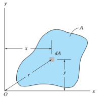
Moment of Inertia for area can also be given as

Where, A is the total area
And k is referred as radius of gyration
Radius of gyration for area of a plate about an axis is defined as the radial distance to a point which would have a same moment of inertia as the plate’s actual distribution of area, if the total area of the plate were concentrated.
It is given by,

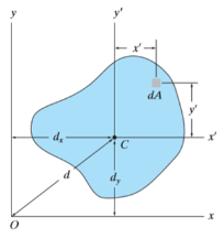
Parallel axis theorem for Area
It states that “the moment of Inertia about an axis is equal to the summation of moment of inertia about the axis passing from centroid of area and the product of total area and square of perpendicular distance between the two axes.”
Mathematically,

Where,  is the moment of inertia about axis passing through the centroid, and d is the perpendicular distance between two axes.
For the system shown below,


Mass moment of Inertia:
The mass moment of inertia of a body is a measure of the body’s resistance to angular acceleration.
Consider a rigid body, rotating about z-axis, as shown in figure.
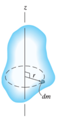
Mass moment of inertia is defined by,

Where, r is the perpendicular distance from the axis of rotation to the arbitrary differential element of the body of mass dm.
The moment of inertia is also written as

Where, m is the total mass of the body
And k is referred as radius of gyration
Radius of gyration for a body rotating about an axis is defined as the radial distance to a point which would have a same moment of inertia as the body’s actual distribution of mass, if the total mass of the plate were concentrated.
In simple words, radius of gyration is the perpendicular distance of the axis of rotation to the point where the entire mass of the body is supposed to be concentrated for dynamic analysis.
It is given by,

Theorem of parallel axes for mass
Theorem of parallel axes states that, “the moment of inertia of the rotating body about an axis is equal to the summation of the moment of inertia of the body about an axis passing through the center of mass and the product of total mass of the body and the square of perpendicular distance between the two axes.”
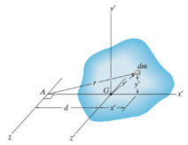
Mathematically,

Where,
 = Moment of inertia about z’ axis passing through the center of mass G
m = total mass of body
d = perpendicular distance between the parallel axes
Theorem of perpendicular axes
It states that, “for the planar element, the moment of inertia about an axis is equal to the summation of moment of inertias about two mutually perpendicular axes.”
Mathematically,

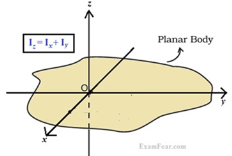
4.4.3 Perpendicular axis theorem, parallel axis theorem
Parallel axis theorem states that
The moment of inertia of a body about an axis parallel to the body passing through its centre is equal to the sum of moment of inertia of body about the axis passing through the centre and product of mass of the body times the square of distance between the two axes.
Parallel Axis Theorem Formula
Parallel axis theorem statement can be expressed as follows:
I = Ic + Mh2
Where,
- I is the moment of inertia of the body
- Ic is the moment of inertia about the centre
- M is the mass of the body
- h2 is the square of the distance between the two axes
Parallel Axis Theorem Derivation
Let Ic be the moment of inertia of an axis which is passing through the center of mass (AB from the figure) and I be the moment of inertia about the axis A’B’ at a distance of h.
Consider a particle of mass m at a distance r from the center of gravity of the body.
Then,
Distance from A’B’ = r + h
I = ∑m (r + h)2
I = ∑m (r2 + h2 + 2rh)
I = ∑mr2 + ∑mh2 + ∑2rh
I = Ic + h2∑m + 2h∑mr
I = Ic + Mh2 + 0
I = Ic + Mh2
Hence, the above is the formula of parallel axis theorem.
Perpendicular axes theorems
It states that , if  be the moments of inertia of figure or plane section about two axis x and y which are perpendicular to each other at point O, then moment of Inertia of that plane section about Z axis which is perpendicular to the plane [&(
 is given by :

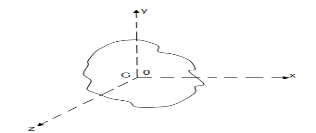
Fig 13
 of plane area about Z axis passing through C.G.
 of plane area about X axis passing through C.G
 of plane area about Y axis passing through C.G
 Is also called as polar moment of Inertia (J)
Key points
1) Parallel Axis Theorem Formula
I = Ic + Mh2
2) Perpendicular axes theorems formula

4.2.5 Radius of gyration, polar moment of inertia.
Radius of gyration
The moment of inertia of a body about an axis is sometimes represented using the radius of gyration. We can define the radius of gyration as the imaginary distance from the centroid at which the area of cross-section is imagined to be focused at a point in order to obtain the same moment of inertia. It is denoted by k.
Radius of Gyration Formula
The formula of moment inertia in terms of the radius of gyration is given as follows:
I = mk2 (1)
Where I is the moment of inertia and m is the mass of the body
Accordingly, the radius of gyration is given as follows
k=√ I/m (2)
The unit of the radius of gyration is mm. By knowing the radius of gyration, one can find the moment of inertia of any complex body equation (1) without any hassle.
Consider a body having n number of particles each having a mass of m. Let the perpendicular distance from the axis of rotation be given by r1, r2, r3,…,rn. We know that the moment of inertia in terms of radius of gyration is given by the equation (1). Substituting the values in the equation, we get the moment of inertia of the body as follows

………… (3)
If all the particles have the same mass then equation (3) becomes

We can write mn as M which signifies the total mass of the body. Now the equation becomes

………… (4)
From equation (4), we get
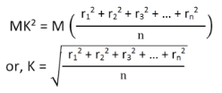
From the above equation, we can infer that the radius of gyration can also be defined as the root-mean-square distance of various particles of the body from the axis of rotation.
What is the use of radius of gyration?
The radius of gyration is used to compare how various structural shapes will behave under compression along an axis. It is used to predict buckling in a compression beam or member.
OR If entire mass of body be assumed to be concentrated at a certain point which is located at a distance K from given axis such that
 2
2
 =
= 
Then
Distance K is known as Radius of Gyration
Thus Radius of Gyration is defined as the Distance from the axis of reference where whole mass of the body is assumed to be concentrated
For plane figure having negligible mass, we can consider area for finding radius of gyration
Thus
M.I. Of an area (plane figure)
 2
2
 
Where, Kxx, Kyy, Kzz is radius of gyration of any area or body about X, y, z, axis respectively | Kxx =   Kyy =   Kzz =   |
Polar Moment Of Inertia
Polar Moment of Inertia is a measure of an object’s capacity to oppose or resist torsion when some amount of torque is applied to it on a specified axis. Torsion, on the other hand, is nothing but the twisting of an object due to an applied torque. Polar moment of inertia basically describes the cylindrical object’s (including its segments) resistance to torsional deformation when torque is applied in a plane that is parallel to the cross-section area or in a plane that is perpendicular to the object’s central axis.
If we put it in simple terms polar moment of inertia is the resistance offered by a beam or shaft when it is being distorted by torsion. This opposition usually arises from the cross-sectional area and it should be noted that it does not depend on the material composition. If the polar moment of inertia is of higher magnitude then the torsional resistance of the object will also be greater. More torque will be required to turn the shaft at an angle.
Nonetheless, it is one of the main aspects of the area moment of inertia and we can use the perpendicular axis theorem to link the two quantities.
Polar Moment Of Inertia Formula
Polar Moment of Inertia is also called the second polar moment of area. It is usually denoted by IZ. However, sometimes J or JZ is also used. Polar Moment of Inertia can be represented mathematically with the given formula;
I or J = r2 dA
Here,
r = distance to the element dA.
Units
The dimension unit of polar moment of inertia is length to the power of four (L4); The SI unit of this property is, meters to the fourth power (m4). In the imperial unit system, it is inches to the fourth power (in4).
Types of Cross-section Polar Moment of Inertia
There are three main types of cross-section polar moment of inertia. They are as follows.
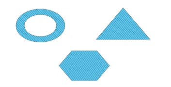
1. Hollow Shaft
To determine the polar moment of inertia we use;
Jhollow = π (R04–R14 )/2
R1 and Ro = inner and outer radius of the hollow shaft.
2. Thin-Walled Shaft
To determine the polar moment of inertia we use;
Jthin = 2πt [R0+Ri /2]3
t = thickness of the thin-walled shaft.
3. Solid Circular Shaft
To determine the polar moment of inertia we use the following formula;
Jsolid = πR4 /2
R = radius of the circular shaft.
Uses and Limitations
Generally, the second polar moment of area is used in determining the angular displacement of a body that is subjected to torque or to calculate the torsion force on a circular body. As for the limitation, the polar moment of inertia is not suitable for analysing shafts and beams with non-circular cross-sections. This is mainly because objects with non-circular cross-sections tend to warp when torque is applied and it further leads to out-of-plane deformations.
Key points
1) Distance K is known as Radius of Gyration
 2
2
 =
= 
Then
2) Radius of Gyration is defined as the Distance from the axis of reference where whole mass of the body is assumed to be concentrated
Reference
1. Engineering Mechanics by S. P. Timoshenko and D. H. Young, McGraw- Hill publication
2. Engineering Mechanics by F L Singer, Harper and Rowe publication
3. Engineering Mechanics by A. P. Boresi and R. J. Schmidt, Brooks/Cole Publication