Unit-5
Kinematics of particles
Rectilinear motion
Motion is one of the most common phenomena we come across in our daily lives. For example, a moving car, a kid running on the road or a fly moving in the air are all said to be in motion. So, in general terms, a body is said to be in motion if it changes its position with respect to a reference point and time. Depending upon the path taken by the particle the motion can be of different types like projectile motion, rectilinear motion, rotational motion, etc. For now, we will only focus on the rectilinear motion which is also known as linear motion.
When we require only one co-ordinate axis along with time to describe the motion of a particle it is said to be in linear motion or rectilinear motion. Some examples of linear motion are a parade of soldiers, a train moving along a straight line, and many more.
Distance and Displacement
So now that we have learned about linear motion we will discuss two terms related to change in position. These are called – ‘Distance’ and ‘Displacement’.
Distance is defined as, The total path length covered during a journey While displacement is defined as, The path length from final position of the particle to the origin O. Consider the following figure:

Fig 1
We have an origin O, measurements to the right of O are taken as a positive while to the left are taken as negative. Suppose a person who starts from origin O reaches point A,
Distance = OA
Displacement = OA
Now he turns and reaches point B,
Distance = OA + AB
Displacement = -OB
As we can see, displacement is negative since it is measured to the left of the origin. From the above example, we can infer that distance is always positive while displacement can either be positive or negative.
Speed and Velocity
These terms are used to describe the rate of change of position. Speed is the rate of change of distance while velocity is the rate of change of displacement. Comparing from above as distance can never be negative so the speed is never negative while velocity can be both positive and negative. In mathematical terms, these are defined as follows:
Speed = Distance Travelled Time Taken
Velocity = (Final position–Initial position) / Time Taken
Examples for Rectilinear Motion
Following are the rectilinear motion examples:
- The use of elevators in public places is an example of rectilinear motion.
- Gravitational forces acting on objects resulting in free fall is an example of rectilinear motion.
- Kids sliding down from a slide are a rectilinear motion.
- The motion of planes in the sky is a rectilinear motion.
Equations of motion
Equations of motion, in physics, are defined as equations that describe the behaviour of a physical system in terms of its motion as a function of time.
There are three equations of motion that can be used to derive components such as displacement(s), velocity (initial and final), time (t) and acceleration (a). The following are the three equation of motion:
- First Equation of Motion : v=u + at
- Second Equation of Motion : s = ut+1/2at2
- Third Equation of Motion : v2=u2+2as
The equations of motion can be derived using the following methods:
- Derivation of equations of motion by Simple Algebraic Method
- Derivation of equations of Motion by Graphical Method
- Derivation equations of Motion by Calculus Method
Key points
1) Speed = Distance Travelled Time Taken
2) Velocity = (Final position–Initial position) Time Taken
3) First Equation of Motion : v=u + at
4) Second Equation of Motion : s = ut+1/2at2
5) Third Equation of Motion : v2=u2+2as
(MOTION CURVES):-
It is a graphical representation of displacement velocity acceleration with time.
(1) Displacement - time curve : (x –t diagram)
(2) 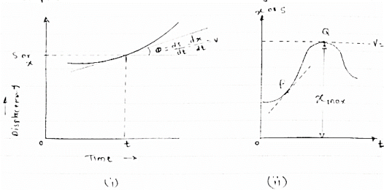
Fig 2
This diagram represents position of particle w.r.t to time here time is taken on x axis & displacement (s or x) is taken on y axis
Slope x t diagram at any point represents the velocity at the instant
∴at any instant t (time)
Velocity is given by v =ds/dt = dx/dt
(2) Velocity time curve: [v - t diagram ]
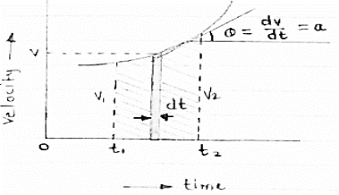
Fig 3
This diagram represents velocity of particle w.r.t. time here velocity is taken on y axis & time on x axis
(a) The slop of v – t diagram represents acceleration at that instant
∴a= dv/dt
(b)area under the curve (v –t curve)represent change in displacement (x or s)between two instant of time
∴let us select elementary trip between t1 & t2.
∴The area of strip da = v x dt
Area bounded between t1 &t2can be find out by integrating area of elementary strip.
∴da= v.dt
∴∫da =∫v.dt
∴ A =
But v=dx/dt b
∴v.dt = dx
∴ A =  = [
= [
∴A = area between (t1 & t2 ) = x2 - x1
(3) Acceleration - time diagram (a –t curves):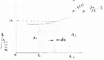
Fig 4
This representation acceleration of particle w.r.t. time‘t’ acceleration is plotted on y axis & time is plotted on x axis.
The slope of the curve representation jerks J = da/dt
The area under a- t diagram between two instant of time (t1 & t2) represent change in velocity
Let us consider an elementary strip
∴ Area of strip da= na.dt
∴ Total area a = 
But a= dv/dt∴ a. Dt = dv
∴ a = 
∴ Area a= v2 - v1
The position coordinate (x) is directly found out from the following moment equation (from a – t diagram)
X1 =x0 + v0 t + mt
Where,
Xt= position of particle at time‘t’
X0 =initial position of particle
V0 = initial velocity of particle
Mt=moment of area under a - t diagram about the instant t.
Velocity - displacement diagram(v -x)
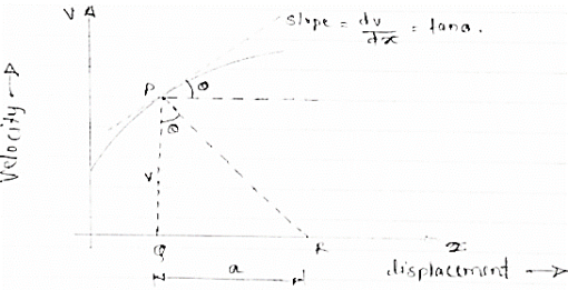
Fig 5
Here plot or graph of velocity (on y axis ) & displacement on (x axis) is drawn.
If a normal is drawn to the tangent on curve the subnormal on x axis represents the acceleration
Let pr is the normal drawn at p
The subnormal =pq.tanθ
=v.tanθ
= v.dv/dx
= a
∴ a = V
∴ Acceleration = velocity x slope of v- x diagram
Numerical on motion diagram
The acceleration versus time for a particle moving along x axis is given in the figure given below. The time interval is 0 to 40 sec for some time interval plot
(1) V-t diagram (2) x – t diagram (3) also find max speed attained & max distance covered
Diagram
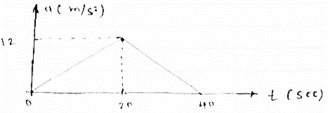
Fig 6
We know that,
Change in velocity= area under a-t diagram from the given a – t diagram
∴at T =20sec
V20 - v0 = 1/2 x 20x12
V20- v0 =120 m/sec
But at T=0 v0 = 0
∴ 20= 120m/sec
Now,
At t =40 sec
∴ v40- v20= ½x 20 x12 = 120
∴ v40 = 120+v20
∴ v40 = 240m/sec
Thus v -t diagram will be as follows
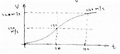
Fig 7
Now from above v -t diagram
Change in displacement = area under v-t diagram
At t=20sec
X20 -X 0 =1/3 x 20x 120 =800m
As (X0 = 0 at t = 0)
∴X20 = 800m
At t =40sec
X40 - X20 = (20x 120) + (2/3 x20 x120)
X40 = 2400+1600+ X20
X40 = 24001600+800
X 40= 4800m
∴ x -t diagram will be as follows
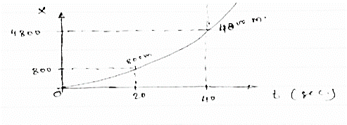
Fig 8
Max speed attained = 240m/sec
Max distance travelled = 4800m
We encounter occasions where one or more objects move in a frame which is non-stationary with respect to another observer. For example, a boat crosses a river that is flowing at some rate or an aeroplane encountering wind during its motion. In all such instances, in order to describe the complete motion of the object, we need to consider the effect that the medium is causing on the object. While doing so, we calculate the relative velocity of the object considering the velocity of the particle as well as the velocity of the medium.
Let us consider two objects, A and B moving with velocities Va and Vb with respect to a common stationary frame of reference, say the ground, a bridge or a fixed platform.
The velocity of the object A relative to the object B can be given as,
Vab= Va −Vb
Similarly, the velocity of the object B relative to that of object a is given by,
Vba=Vb − Va
From the above two expressions, we can see that
Vab=−Vba
Although the magnitude of both the relative velocities is equal to each other Mathematically
|Vab|=|Vba|
Examples of relative Velocity
We can understand the concept of relative velocity more clearly with the help of the following example.
Example: A plane is travelling at velocity 100 km/hr, in the southward direction. It encounters wind travelling in the west direction at a rate of 25 km/hr. Calculate the resultant velocity of the plane.
Given, the velocity of the wind = Vw = 25 km/hr
The velocity of the plane = Va= 100 km/hr
The relative velocity of the plane with respect to the ground can be given as
The angle between the velocity of the wind and that of the plane is 90°. Using the Pythagorean Theorem the resultant velocity can be calculated as,
R2= (100 km/hr.) 2 + (25 km/hr.)2
R2= 10 000 km2/hr2 + 625 km2/hr2
R2= 10 625 km2/hr2
Hence, R = 103.077 km/hr
Using trigonometry, the angle made by the resultant velocity with respect to the horizontal plane can be given as,
Tan Θ= (window velocity / aiprplane velocity)
Tan Θ= (25/100)
Θ=tan−1 (1/4)
Θ=14.0∘
Curvilinear motion
Curvilinear motion is defined as motion that occurs when a particle travels along a curved path. The curved path can be in two dimensions (in a plane), or in three dimensions. This type of motion is more complex than rectilinear (straight-line) motion.
Three-dimensional curvilinear motion describes the most general case of motion for a particle. To find the velocity and acceleration of a particle experiencing curvilinear motion one only needs to know the position of the particle as a function of time.
Let’s say we are given the position of a particle P in three-dimensional Cartesian (x,y,z) coordinates, with respect to time, where
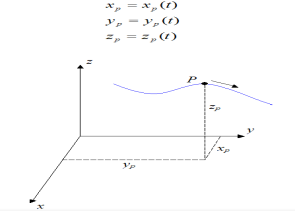
Fig 9
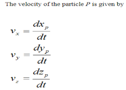
The acceleration of the particle P is given by
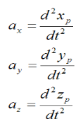
As you can see, if we know the position of a particle as a function of time, it is a fairly simple exercise to find the velocity and acceleration. You simply take the first derivative to find the velocity and the second derivative to find the acceleration.
The magnitude of the velocity of particle P is given by

The magnitude of the acceleration of particle P is given by 
Note that the direction of velocity of the particle P is always tangent to the curve (i.e. the path travelled, denoted by the blue curve in the figure above). But the direction of acceleration is generally not tangent to the curve.
However, the acceleration component tangent to the curve is equal to the time derivative of the magnitude of velocity of the particle P (along the curve). In other words, if vt is the magnitude of the particle velocity (tangent to the curve), the acceleration component of the particle tangent to the curve (at) is simply

In addition, the acceleration component normal to the curve (an) is given by

Where R is the radius of curvature of the curve at a given point on the curve (xp, yp, zp)
The figure below illustrates the acceleration components at and an at a given point on the curve (xp,yp,zp).
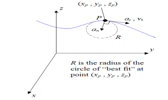
Fig 10
For the specific case where the path of the blue curve is given by y = f(x) (two-dimensional motion), the radius of curvature R is given by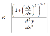
where |x| means the “absolute value” of x. For example, |-2.5| = 2.5, and |3.1| = 3.1.
However, it is usually not necessary to know the radius of curvature R along a curve. But nonetheless, it is informative to understand it on the basis of its relationship to the normal acceleration (an).
When a particle moves along a curved path, then motion of the particle is said to be curvilinear.
Basic terminology used to describe curvilinear motion: -
- Position vector: - (
 )
)
- Consider that particle is moving along the curve as shown in figure.
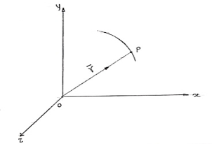
Fig 11
b. Let ‘P’ is the position of particle at any time instant ‘t’.
c. Let we have fixed reference axes x,y,z as shown.
d. The line ‘OP’ represents the position of particle &it is known as position vector of particle at time‘t’.
 Position vector
e.  = xi + yj + zk and
 - Magnitude of position
2. Displacement and distance:
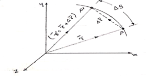
- Consider that particle is moving along the plane curve P-P’ as shown in figure
- Let particle is located at point P at time instant‘t’.
Position of particle at point P is given by vector  . Now after time (t + ∆t), let particle is moved to a new position P’. This position of particle is given by the vector (
 )
)
- The vector joining P & P’ is ∆
 . (dashed line)
∆ = change of position of particle during the time interval ∆t.
∆ = displacement of particle.
- The distance travelled by the particle along the curve from point P to P’ is ∆s. This is measured along the curved path & is scalar quantity.
3. Velocity :
In above figure ∆ = displacement vector
∆r = displacement of particle (magnitude).
∆t = time taken by particle to move from P to P’.
Avg. Velocity =  = vavg.
- When the time interval approaches to zero, ∆t → 0.
Instantaneous velocity at P will be,
V = 
V = 
Speed = 
4. Acceleration: -
Avg. Acceleration a = 
For very small interval of time ∆t → 0
Thus a =  &
&
The acceleration at point P = 
(Instantaneous acceleration)
Key points
1) Avg. Velocity =  = vavg.
2) Speed = 
3) The magnitude of the velocity of particle P is given by

4) The magnitude of the acceleration of particle P is given by 
Angular motion
The motion of a body about a fixed point or fixed axis. It is equal to the angle passed over at the point or axis by a line drawn to the body.
Objects don't always travel in straight lines. For situations involving circular motion, such as the pendulum of a clock or a door swinging.
Angular motion includes rotating bodies, levers, stability, and moment of force/torque, axis of rotation, moment of inertia and angular momentum.
Formula | Linear | Angular |
Velocity | v=Δs/Δt | ω=ΔΘ/Δt |
Acceleration | a=Δv/Δt | a=Δω/Δt |
Displacement | s=vit+1/2at2 | Θ=vit+1/2αt2 |
Motion with time cancelled out | v2f−v2i=2as | ω2f−ω2i=2αΘ |
- Displacement – In linear motion, we use‘s’ to quantify the linear distance travelled. In angular motion, we use ‘θ’ for the same to quantify the angular distance, and it is measured in radians.
- Velocity – In linear motion, we use ‘v’ to denote velocity while in angular motion, we use ‘ω’ to indicate angular velocity. Angular velocity is the number of radians covered per second.
- Acceleration – We use ‘a’ to denote linear acceleration, while we use ‘α’ to mean the angular acceleration. The unit for angular acceleration is radians per second2.
Now that we have discussed the variations in linear and angular motions let us look at the formulas for both linear and angular motion.
Formula | Linear | Angular |
Velocity | v=Δs / Δt | ω=ΔΘ / Δt |
Acceleration | a=Δv / Δt | a=Δω /Δt |
Displacement | s=vit+1/2at2 | Θ=vit+1/2αt2 |
Motion with time cancelled out | v2f−v2i=2as | ω2f−ω2i=2αΘ |
Let us consider an example to understand the relationship between linear and angular velocity better. Say, for example, you have a ball tied to a string. It makes a complete circle, 2π radians in 0.5 seconds. The angular velocity of the ball can easily be found out using the formula
ω=ΔΘ / Δt =2πradian / 0.5s
=4πrad/s
Another demonstration of the usefulness of radians in measuring angles is that the linear speed can easily be related to the angular speed.
The linear speed can be easily related to the angular speed as follows:
Consider the equation,
ω=ΔΘ / Δt
Multiply both the sides by the radius r,
rω= r.ΔΘ/Δt
The term rΔΘ denotes the distance travelled by an object moving in a circle of radius r; hence, this equation becomes
rω = Δs /Δt
You may recognize the right side of this equation as the equation for speed. The relationship between linear and angular speed can be written as follows:
rω =v
Tangential and Radial Acceleration
The object under motion can undergo a change in its speed. The measure of the rate of change in its speed along with direction with respect to time is called acceleration. The motion of the object can be linear or circular. Thus, the acceleration involved in linear motion is called linear acceleration. The acceleration involved in a circular motion is called angular acceleration.
If we recall circular motion here distance covered will be along the curved path. (Circumference of a circle) The velocity involved is angular velocity and not linear velocity. Similarly, the acceleration involved is centripetal acceleration
Radial Acceleration Definition
In a uniform circular motion, “the acceleration of the object is along the radius, directed towards the centre” is called radial acceleration.
OR
Just because an object moves in a circle, it has a centripetal acceleration ac, directed toward the center. We know this centripetal acceleration is given by
ac = v2 / r
This centripetal acceleration is directed along a radius so it may also be called the radial acceleration ar.
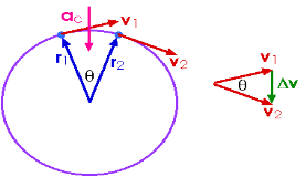
Fig 13
Tangential Component
The tangential component is defined as the component of angular acceleration tangential to the circular path. The unit of measurement is m.s-2. The mathematical representation is given as
at = v2−v1/ t Where,
- at is the tangential component
- t is the time period
- v1 and v2 are the respective velocities of the two objects in a circular motion.
If the speed is not constant, then there is also a tangential acceleration at.
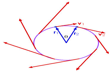
Fig 14
The tangential acceleration is, indeed, tangent to the path of the particle's motion.
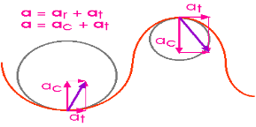
Fig 15
Motion of a projectile
When a particle is freely thrown in the air along any direction other than vertical it follows it follows the parabolic path .The motion of a particle along this parabolic path is called as projectile motion.
i.e. when we project the particle in the space, its motion is a combination of horizontal & vertical motion. This motion is called as projectile Motion.
Wind Resistance, curvature & rotation of the earth affects the actual path.
But these parameters are neglected.
- The path Traced by projectile is called as Trajectory.”
- The motion of projectile in Horizontal direction is uniform motion.
- Ax = Horizontal component of acceleration = 0
- The acceleration in vertical direction is affected by gravity. Thus motion in y direction is considered as “Motion under gravity.”
:.  y = -
y = -
Basic Terms involved in the projectile Motion
1) Time of flight :- (t)
- The time by the projectile to move from point of projection to the point of target is called as “Time of flight.”
- It is the total time during which projectile remains in space.
2) “Horizontal Range” :- (R)
It is Horizontal distance from point of projection the point of target. OR It is Horizontal distance bet/n point of projection & point of landing.
3) Maximum Height :- (H) or (Hmax)
It is the vertical distance bet/n the point of projection and the point © where the vertical component of velocity is zero.
4) Angle of projection :(  )
)
- It is the angle made by velocity with the Horizontal.
- If velocity is directed up the horizontal, then it is called as angle of elevation.
-If the velocity is directed down the Horizontal, then it is called as angle of depression.
5) Trajectory:-
It is the path traced by a projectile during its motion. It is parabolic in nature.
Projectile on Horizontal plane
Consider a projectile projected from point A with
u= initial velocity of projection &
 = Angle of projection.
Let t = total time of flight.
Thus projectile will land at point b after time‘t’ Both point A& B are Qn H.P
Diagram
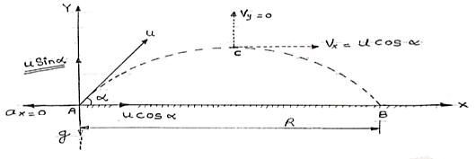
Fig 16
As the air resistance is neglected, the motion in X-direction is uniform motion & y dirn motion is Motion under Gravity”.
a) Time of flight (t)
t 2 u sin /
/
b) Horizontal Range (R)
R = u2. Sin2 /
/
c) Maximum Range (R max)
For maximum Range angle of projection must be 45
R max = u2/
d) Maximum Height
H = u2. Sin2 /2
/2
Derivation of path Equation
[Equation of Trajectory]
Vx= u cos = constant.
Vy = u sin 

Fig 13
Consider a particle projected from A with initial velocity ‘u’ & angle of projection ‘ ’.
’.
Let after time ‘t’ the particle has reached at point p (x, y).
Consider the motion of projectile in X dirn (VM):- [ A p]
p]
S= velocity * time
X = u cos . t1
. t1
:. t1 = X/ u cos . t1
. t1
:. t1 = X/ u cos . --------- (1)
Consider the motion of projectile in y dir/n (m. U.G) [A  p]
p]
:. Sy= uyt1- ½  t2
t2
Y = u sin  .t1 – 1/2
 t12
t12
From equation (1), put the value of time t1
:. y = usin  .(x/ucos
 .) – ½
  (x/ u-cos
 .)2
.)2
:. y = X. Tan - gx2/u2 cos2
:. y X. Tan - gX2/2u2 cos2
Equation of Trajectory Projectile on Inclined plane
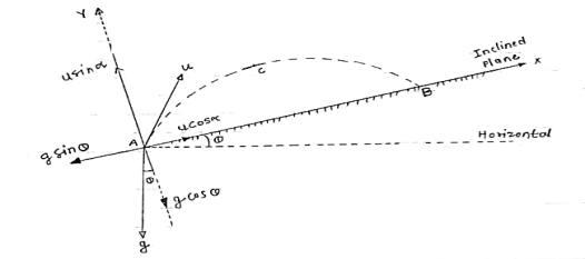
Fig 14
Let projectile is projected from point A.
Let angle projection with (inclined) plane.
 = Angle of inclined plane with Horizontal.
Now let us select X axis along the inclined plane and y –axis perpendicular to the inclined plane.
:. X component of velocity = u cos
:. Y - ----- -------------------- u sin 
Similarly for gravitation Acceleration ‘g’
X component = g sin
y component = g cos 
a) Time of flight (t) b) Range along the plane (R)
t= 2u. Sin  /g cos
  R= 2 u2 sin
 / g cos2
  . Cos (
 +
+ )
)
c) Maximum Range (Rmax) d) Max. Height (lar to plane)
Rmax = u2/g (1+sin ) H = u2 sin2
 / 2g. Cos
*Special cases of projectile*
*projectile projected with Horizontal velocity:-*
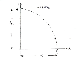 X motion
Consider motion A  B
B
(V.M)
X = u*t
Consider Motion (y- motion)
From A B (M.V.G)
S = ut + ½ gt2
h= 0 + ½gt2
:. t=  2h/g
2h/g
:. Horizontal distance, = X = u 
Y = x tanx - gx2/u2 cos 2  -eqn of trnjectory
But  = 0 At point A. Fig 15
:. –h = -y = 0 - gx2/2u2
:. h = gx2 / 2u2
*for given values of u, two angles gives us the same Range.
 1 =
1 =  ,
,  2 = π/2 -
Reference:
1. Engineering Mechanics by S. P. Timoshenko and D. H. Young, McGraw- Hill publication
2. Engineering Mechanics by J. L. Meriam and Craige John Willey
3. Engineering Mechanics by F L Singer, Harper and Rowe publication
4. Engineering Mechanics by A. P. Boresi and R. J. Schmidt, Brooks/Cole Publication