Unit-6
Kinetics of Particles
Newton’s First Law of Motion
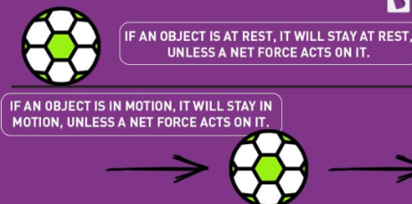
The first law of motion implies that things cannot start, stop, or change direction all by themselves. It requires some force from the outside to cause such a change. This property of massive bodies to resist changes in their state of motion is called inertia. Newton’s first law is also known as the law of inertia.
Newton’s 1st law states that a body at rest or uniform motion will continue to be at rest or uniform motion until and unless a net external force acts on it.
Newton’s Second Law of Motion
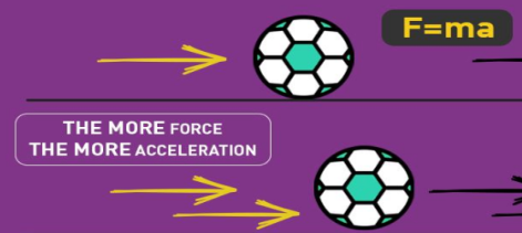
The second law of motion describes what happens to the massive body when acted upon by an external force. The 2nd law of motion states that the force acting on the body is equal to the product of its mass and acceleration.
Newton’s 2nd law states that the acceleration of an object as produced by a net force is directly proportional to the magnitude of the net force, in the same direction as the net force, and inversely proportional to the mass of the object.
Newton’s second law describes precisely how much an object will accelerate for a given net force.
Mathematically, we express the second law of motion as follows:
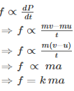
In the equation, k is the constant of proportionality, and it is equal to 1 when the values are taken in SI unit. Hence, the final expression will be,
F=ma
Newton’s Third Law of Motion

The third law of motion describes what happens to the body when it exerts a force on another body.
The Newton’s 3rd law states that for every action there is an equal and opposite reaction.
When two bodies interact, they apply force on each other that are equal in magnitude and opposite in direction. To understand Newton’s third law with the help of an example, let us consider a book resting on a table. The book applies a downward force equal to its weight on the table. According to the third law of motion, the table applies an equal and opposite force on the book. This force occurs because the book slightly deforms the table; as a result, the table pushes back on the book like a coiled spring.
It states that the sum of external force acting on a body and inertia force is always equal to zero.
∑
- For rectilinear motion
∑ or ∑
or ∑
2. For universal motion
∑ Or
Or
∑
D’-ALMBERTS Principle for universal motion :-
D’-ALMBERTS Principle for universal motion in Cartesian coordinates:-
∑
∑
∑
∑
D’-ALMBERTS principle for curvilinear motion in path variables (tangential and normal coordinates) :-
∑ AND ∑
AND ∑
∑ AND ∑
AND ∑
For radial and transverse coordinates :-
∑ AND ∑
AND ∑
Therefore,
∑ AND ∑
AND ∑
Motion is one of the most common phenomena we come across in our daily lives. For example, a moving car, a kid running on the road or a fly moving in the air are all said to be in motion. So, in general terms, a body is said to be in motion if it changes its position with respect to a reference point and time. Depending upon the path taken by the particle the motion can be of different types like projectile motion, rectilinear motion, rotational motion, etc. For now, we will only focus on the rectilinear motion which is also known as linear motion.
When we require only one co-ordinate axis along with time to describe the motion of a particle it is said to be in linear motion or rectilinear motion. Some examples of linear motion are a parade of soldiers, a train moving along a straight line, and many more.
Distance and Displacement
So now that we have learned about linear motion we will discuss two terms related to change in position. These are called – ‘Distance’ and ‘Displacement’.
Distance is defined as, The total path length covered during a journey While displacement is defined as, The path length from final position of the particle to the origin O. Consider the following figure:

We have an origin O, measurements to the right of O are taken as a positive while to the left are taken as negative. Suppose a person who starts from origin O reaches point A,
Distance = OA
Displacement = OA
Now he turns and reaches point B,
Distance = OA + AB
Displacement = -OB
As we can see, displacement is negative since it is measured to the left of the origin. From the above example, we can infer that distance is always positive while displacement can either be positive or negative.
Speed and Velocity
These terms are used to describe the rate of change of position. Speed is the rate of change of distance while velocity is the rate of change of displacement. Comparing from above as distance can never be negative so the speed is never negative while velocity can be both positive and negative. In mathematical terms, these are defined as follows:
Speed = Distance Travelled Time Taken
Velocity = (Final position–Initial position) Time Taken
Examples for Rectilinear Motion
Following are the rectilinear motion examples:
- The use of elevators in public places is an example of rectilinear motion.
- Gravitational forces acting on objects resulting in free fall is an example of rectilinear motion.
- Kids sliding down from a slide are a rectilinear motion.
- The motion of planes in the sky is a rectilinear motion.
Motion of Connected Bodies
When objects are connected by strings and a force F is applied either vertically or horizontally or along an inclined plane, it produces a tension T in the string, which affects the acceleration to an extent. Let us discuss various cases for the same.
Case 1: Vertical motion
Consider two blocks of masses m1 and m2 (m1> m2) connected by a light and inextensible string that passes over a pulley as shown in Figure 1
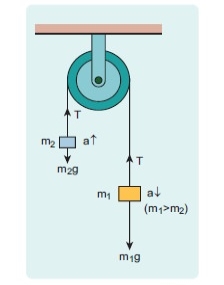
Fig 1 Two block connected by string
Let the tension in the string be T and acceleration a. When the system is released, both the blocks start moving, m2 vertically upward and m1 downward with same acceleration a. The gravitational force m1g on mass m1 is used in lifting the mass m2.
The upward direction is chosen as y direction. The free body diagrams of both masses are shown in Figure 2.
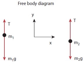
Fig 2 free body diagram of mass m1 and m2
Applying Newton’s second law for mass m2

The left hand side of the above equation is the total force that acts on m2 and the right hand side is the product of mass and acceleration of m2 in y direction.
By comparing the components on both sides, we get
T – m2g = m2a…equation 1
Similarly applying newton second law for mass m1

As mass m1 moves downward (-j) its acceleration is along (-j)
By comparing the components on both sides, we get
T – m1g = -m1a
m1g - T = m1a…………2
Applying equation 1 and 2
m1g – m2g = m1a + m2a
(m1– m2) g = (m1 + m2)a….3
From equation 3 the acceleration of both the masses is
a = [(m1– m2) / (m1 + m2)] g ……4
If both the masses are equal (m1=m2) from equation 4
a = 0
This shows that if the masses are equal, there is no acceleration and the system as a whole will be at rest.
To find the tension acting on the string, substitute the acceleration from the equation (4) into the equation (1).
T – m2 g = m2 [(m1– m2) / (m1 + m2)] g
T = m2 g + m2 [(m1– m2) / (m1 + m2)] g………..5
By taking m2g common in the RHS of equation (5)
T = m2 g [1+ (m1– m2) / (m1 + m2)]
T = m2 g [(m1+m2 +m1 - m2)/m1+m2]
T = (2m1m2/m1+m2) g
Equation gives only magnitude of acceleration.
For mass m1 the acceleration vector is given by

For mass m2 the acceleration vector is given by

Case 2: Horizontal motion
In this case, mass m2 is kept on a horizontal table and mass m1 is hanging through a small pulley as shown in Figure 3. Assume that there is no friction on the surface.
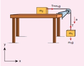
Fig 3 Block in horizontal motion
As both the blocks are connected to the unstretchable string, if m1 moves with an acceleration a downward then m2 also moves with the same acceleration a horizontally
The forces acting on mass m2 are
i. Downward gravitational force (m2g)
Ii. Upward normal force (N) exerted by the surface
Iii. Horizontal tension (T) exerted by the string
The forces acting on mass m1 are
i. Downward gravitational force (m1g)
Ii. Tension (T) acting upwards
The free body diagrams for both the masses are shown in Figure 4
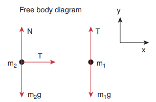
Fig 4 Free body diagram of masses m1 and m2
Applying Newton’s second law for m1

By comparing the components on both sides of above equation
T – m1g = -m1a…..6
Applying newton second law for m2

By comparing the components on both sides of above equation
T = m2a….7
There is no acceleration along y direction for m2

By comparing the component on both sides of the above equation
N-m2g=0
N = m2g……8
By substituting equation 7 in equation 6.we can find the tension T
m2a – m1g = -m1a
m2a + m1a = m1g
a = [(m1 / (m1 + m2)] g…..9
Tension in the string can be obtained by substituting equation (9) in equation (7)
T = [(m1 m2/ (m1 + m2)] g…..10
Comparing motion in both cases, it is clear that the tension in the string for horizontal motion is half of the tension for vertical motion for same set of masses and strings.
This result has an important application in industries. The ropes used in conveyor belts (horizontal motion) work for longer duration than those of cranes and lifts (vertical motion).
Motion of a lift
Consider a lift (elevator or cage) carrying some mass and moving with uniform acceleration.
Let
m = Mass carried by the lift in kg,
a = Uniform acceleration of the lift in m/s2, and
R = Reaction of the lift or tension in the cable supporting the lift in newton’s
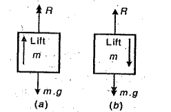
Fig 5
When the lift is moving upwards as shown in Fig.5(a), then
R – mg = ma or R = mg + ma = m (g + a)
When the lift is moving downwards as shown in Fig. 5(b), then
mg – R = ma or R = mg – ma = m (g – a)
Circular motion is described as a movement of an object while rotating along a circular path. Circular motion can be either uniform or non-uniform. During uniform circular motion the angular rate of rotation and speed will be constant while during non-uniform motion the rate of rotation keeps changing.
Some of the most common examples of circular motion include man-made satellite that revolves around the earth, a rotating ceiling fan, a moving car’s wheel, the blades in a windmill, and gears in gas turbines.
A particle is said to execute circular motion when it moves along the circumference of a circular path. An important aspect of circular motion is that the direction of motion is changing continuously unlike in the case of linear motion. Hence circular motion can also be described in terms of angular variables.
Angular Displacement
It is defined as the angle turned by a rotating particle per unit time. It is represented by ∆θ and measured in radians. In the figure, angular displacement is measured between the position vectors rand r’.
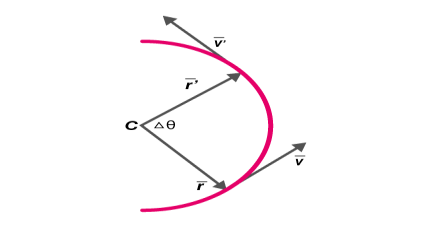
Fig 6
Angular Velocity
It is defined as the rate of change in angular displacement of a particle in a circular motion. It is denoted by
ω = lim∆t→0 (∆θ/∆t) = dθ/dt
Angular velocity is measured in rad/s. Apart from angular velocity and angular speed, a particle in circular motion also possesses linear velocity and corresponding linear speed.
v= ds/dt
v= |ds/dt|; s is the displacement of the particle
Relation Between Linear Speed (V) And Angular Speed(Ω)
In vector form
v= ω x r
Where r is the position vector of the particle measured with respect to the centre of the circle
(Or)
v = rω
The acceleration of a particle in circular motion has two components :
- Tangential acceleration at: This is the component of acceleration in the direction of the velocity of the particle.
at= d|v|/dt
- Radial acceleration ar: This is the component of acceleration directed towards the centre of the circle. This component causes a change in the direction of the velocity of a particle in a circular motion.
ar= v2/r = rω2
Angular Acceleration
It is defined as the rate of change of angular velocity of the rotating particle. It is measured in rad/s2
α = dω /dt = d2θ/dt2
Circular motion can be uniform and non-uniform depending on the nature of acceleration of the particle. The motion is called uniform circular motion when the particle is moving along a circular path possessing a constant speed.
During circular motion, the velocity vector changes its direction at each point on the circle. This implies that the radial component of acceleration is always non-zero. The tangential component can take a positive or negative value in the case of non-uniform circular motion and a zero value in the case of uniform circular motion.
We understand that the acceleration of a particle in a circular motion is always directed towards the centre and is given by v2/r. Applying Newton’s second law of motion in this situation;
Fcen = mv2/r
Where m is the mass of the particle
Fc is the centripetal force directed towards the centre of the circular path as illustrated in
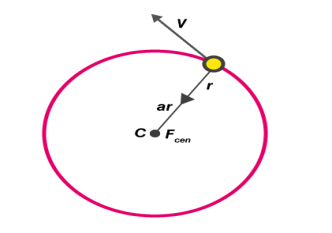
Fig 7
Examples of centripetal forces include gravitational force, the tension in a string and friction.
Application of Newton’s Laws of Motion
Let us understand the application of Newton’s laws of motion in two different scenarios. The motion of a vehicle will be on either:
At Level Road
At an instant when a vehicle makes a turn on a level road, there are three different forces acting.
- The weight of the car W= mg
- Frictional force ff
- Normal reaction N
In the vertical direction N-mg = 0
N = mg
The centripetal acceleration for circular motion is provided by static friction. This friction holds back the vehicle from moving away from the circle.
ff = mv2/r ≤ µN
µis the coefficient of static friction
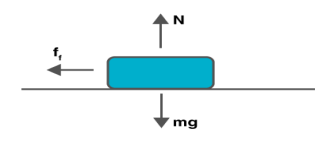
Fig 8
vmax = μrg
This implies that for a circular path of given radius and µ, there is a maximum possible speed of the vehicle.
At Banked Roads
The effect of friction on the motion of a vehicle on a circular road can be minimized if the road is slightly raised on the outer end. This is called banking. Let the road be banked at an angle θ0 as illustrated in the figure.
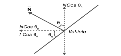
Fig 9
Net force along the vertical direction is zero since there is no acceleration along this direction.
Therefore,
N cos θ0 = ff sin θ0 + mg …..(1)
Mv2/r = N sin θ0 + ff cos θ0…. (2)
Substituting ff = µN in equations (1) and (2) gives vmax
N cos θ0 = µN sin θ0 + mg
Mv2/r = N sin θ0 + µN cos θ0
Solving the above equations gives us,
vmax = √rgtanθ0
Rotational Kinetic Energy
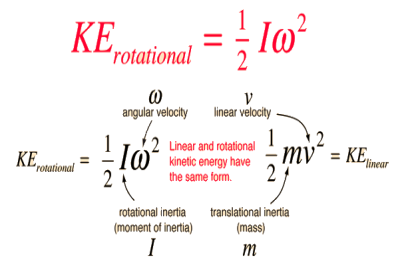
The kinetic energy of a rotating object is analogous to linear kinetic energy and can be expressed in terms of the moment of inertia and angular velocity. The total kinetic energy of an extended object can be expressed as the sum of the translational kinetic energy of the center of mass and the rotational kinetic energy about the center of mass. For a given fixed axis of rotation, the rotational kinetic energy can be expressed in the form
The expressions for rotational and linear kinetic energy can be developed in a parallel manner from the work-energy principle. Consider the following parallel between a constant torque exerted on a flywheel with moment of inertia I and a constant force exerted on a mass m, both starting from rest.
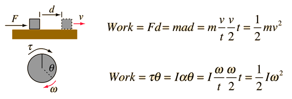
For the linear case, starting from rest, the acceleration from Newton's second law is equal to the final velocity divided by the time and the average velocity is half the final velocity, showing that the work done on the block gives it a kinetic energy equal to the work done. For the rotational case, also starting from rest, the rotational work is τθ and the angular acceleration α given to the flywheel is obtained from Newton's second law for rotation. The angular acceleration is equal to the final angular velocity divided by the time and the average angular velocity is equal to half the final angular velocity. It follows that the rotational kinetic energy given to the flywheel is equal to the work done by the torque.
Mass moment of inertia
Moment Of Inertia of Cylinder
The moment of inertia of cylinder about a perpendicular axis passing through its centre is determined by;
Ix = ¼ MR2 + 1/12 ML2
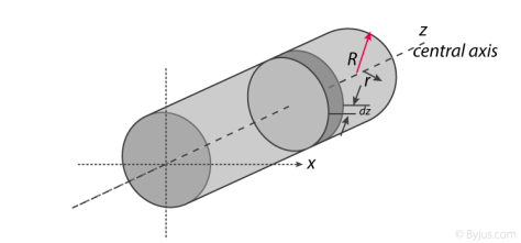
Fig 10
We will look at the derivation of this formula below.
Generally, the derivation involves 3 primary steps. It includes;
- Splitting the cylinder into infinitesimally thin disks and stating the moment of inertia.
- Using both parallel and perpendicular axis theorems to determine the expression.
- Integrating over the length of the cylinder.
1. Cutting the cylinder into infinitesimally thin disks
We will consider the cylinder having mass M, radius R, length L and the z-axis which passes through the central axis.
Here,
Density ρ = M / V
Next, we will consider the moment of inertia of the infinitesimally thin disks with thickness dz.
First, we assume that dm is the mass of each disk, We get;
Dm = ρ X Volume of disk
Dm = M / V X (πr2.dz)
We take V = area of circular face X length which is = πr2L. Now we obtain;
Dm = M / πr2L X (πr2.dz)
Dm = M / L X dz
The moment of inertia about the central axis is given as;
Dlz = ½ dmR2
Use of Perpendicular Axis Theorem
We now apply the perpendicular axis theorem which gives us;
Dlz = dlx + dly
Here, if we need to consider that both x and y moments of inertia are equal by symmetry.
Dlx = dly
We need to combine the equations for the perpendicular axis theorem and symmetry. We get;
Dlx = dlz / 2
Now we substitute lz from the equation above.
Dlx = ½ x ½ dmR2
Dlx = ¼ dmR2
Alternatively, for the x-axis, we use the parallel axis theorem to find the moment of inertia. We get;
Dlx = ¼ dmR2 + dmz2
Integration
Now we conduct integration over the length of the cylinder to express the mass element dm in terms of z. We take the integral from z=0 to z=L.
Ix = o∫L dlx
Ix = o∫L ¼ dzR2 + o∫L ¼ z2 m / l dz
Ix = ¼ M / L R2z + M / L Z3 / 3]0L
Since it is a definite form of integral we ignore the constant. We will now have;
Ix = ¼ M / L R2 L + M / 3L 2L3 / 23
Ix = ¼ MR2 + 1/12 ML2
Therefore, I =1/2 MR2
Moment of Inertia of Sphere
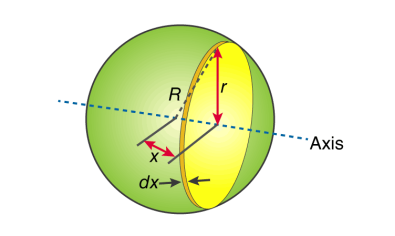
Fig 11
First, we take the moment of inertia of a disc that is thin. It is given as;
I = ½ MR2
In this case, we write it as;
DI (infinitesimally moment of inertia element) = ½ r2dm
Find the dm and dv using;
Dm = p dV
p = moment of a thin disk of mass dm
Dv = expressing mass dm in terms of density and volume
DV = π r2 dx
Now we replace dV into dm. We get;
Dm = p π r2 dx
And finally, we replace dm with dI.
DI = ½ p π r4 dx
The next step involves adding x to the equation. If we look at the diagram we see that r, R and x forms a triangle. Now we will use Pythagoras theorem which gives us;
r2 = R2 – x2
Now if we substitute the values we get;
DI = ½ p π (R2 – x2)2 dx
This leads to:
I = ½ p π -R∫R (R2 – x2)2 dx
After integration and expanding we get;
I = pπ 8/15 R5
Additionally, we have to find the density as well. For that we use;
P (density) = M (mass) / V (volume)
p = M (mass) / (4/3 πR3)
If we substitute all the values;
I = 8/15 π [M / (4/3 πR3)] R5
I = ⅖ MR2
Moment of inertia of Solid Cone
We will take a solid cone where its axis will pass through the centre with radius = r, height = h. We will need to determine the mass though.

Fig 12
We take the elemental disc whose mass is given by;
Dm = ρ ⋅ π r2dz
Density is given as;
ρ = M / V = M / (⅓ π R2h)
With this, we will calculate the dm.
Dm = [M / (⅓ π R2h)] X π r2dz
Dm = (3M / R2h) X r2 dz
If we consider the similarity of the triangle, then we have;
R / r = h / z
r = R .z / h
Now,
Dm = (3M / R2h) (R2 / h2) ⋅ z2dz
Dm = (3M / h3). z2dz
If we consider z-axis, the moment of inertia of the elemental disk will be;
DI = ½ dmr2
DI = ½ ⋅ (3M / h3) . z2 ⋅ (z2 R2 / h2) dz
DI = 3 / 2 ⋅ M R2 / h5 X z4dz
Now we will follow the integration process. Here;
I = 3 / 2 ⋅ M R2 / h5 o∫h z4dz
I = 3 / 2 ⋅ M R2 / h5 [z5 / 5 ]oh
I = 3 / 2 ⋅ M R2 / h5 ⋅ h5 / 5
Therefore, I = 3/10 MR2
Reference:
1. Engineering Mechanics by S. P. Timoshenko and D. H. Young, McGraw- Hill publication
2. Engineering Mechanics by J. L. Meriam and Craige John Willey
3. Engineering Mechanics by F L Singer, Harper and Rowe publication
4. Engineering Mechanics by A. P. Boresi and R. J. Schmidt, Brooks/Cole Publication