UNIT -7
OPTICAL FIBERS
OPTICAL FIBRE
A cable that is used to transmit the data through fibres (threads) or plastic (glass) is known as an optical fibre cable. This cable includes a pack of glass threads that transmits modulated messages over light waves.
Principle: Optical Fibre works on the principle of Total Internal Reflection.
Total internal reflection:-
When the light ray travels from denser medium to rarer medium the refracted ray bends away from the normal. When the angle of incidence is greater than the critical angle, the refracted ray again reflects into the same medium. This phenomenon is called total internal reflection. The refracted ray bends towards the normal as the ray travels from rarer medium to denser medium. The refracted ray bends away from the normal as it travels from denser medium to rarer medium.
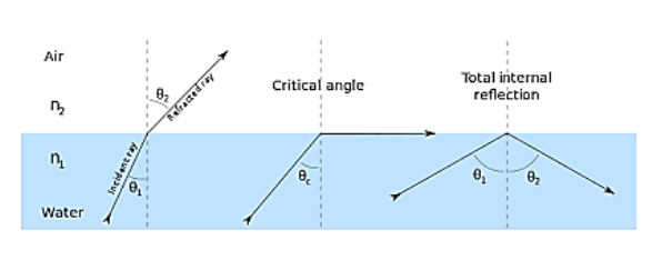
Figure 1 – Total Internal Reflection
When light passes from a medium with one index of refraction (m1), to another medium with a lower index of refraction (m2), it bends or refracts away from an imaginary line perpendicular to the surface (normal line). As the angle of the beam through m1 becomes greater with respect to the normal line, the refracted light through m2 bends further away from the line.
At one particular angle (critical angle), the refracted light will not go into m2, but instead will travel along the surface between the two media (sine [critical angle] = n2/n1 where n1 and n2 are the indices of refraction [n1 is greater than n2]). If the beam through m1 is greater than the critical angle, then the refracted beam will be reflected entirely back into m1 (total internal reflection), even though m2 may be transparent.
In physics, the critical angle is described with respect to the normal line. In fiber optics, the critical angle is described with respect to the parallel axis running down the middle of the fiber. Therefore, the fiber-optic critical angle = (90 degrees - physics critical angle).
In an optical fiber, the light travels through the core (m1, high index of refraction) by constantly reflecting from the cladding (m2, lower index of refraction) because the angle of the light is always greater than the critical angle. Light reflects from the cladding no matter what angle the fiber itself gets bent at, even if it's a full circle.
Because the cladding does not absorb any light from the core, the light wave can travel great distances. However, some of the light signal degrades within the fiber, mostly due to impurities in the glass. The extent that the signal degrades depends upon the purity of the glass and the wavelength of the transmitted light
When the angle of incidence (θ1) is progressively increased, there will be progressive increase of refractive angle (θ2). At some condition (θ1) the refractive angle (θ2) becomes 90o to the normal. When this happens the refracted light ray travels along the interface. The angle of incidence (θ1) at the point at which the refractive angle (θ1) becomes 90 degree is called the critical angle.
It is denoted by θc. The critical angle is defined as the minimum angle of incidence (θ1) at which the ray strikes the interface of two media and causes an angle of refraction (θ2) equal to 90o. Figure 1 shows critical angle refraction
Hence at critical angle θ1= θc and θ2= 90o .
Using Snell‘s law: n1 sin θ1 = n2 sin θ2
n1 sin θc = n2 sin90o
Sin θc = n2 / n1
θc = sin-1 (n2 / n1)
The actual value of critical angle is dependent upon combination of materials present on each side of boundary.
CHARACTERISTICS OF OPTICAL FIBRE
- It has a large bandwidth.
- The optical frequency of 2 x 10¹⁴ Hz can be used and hence the system has higher bandwidth.
- Thus optical fibres have greater information-carrying capacity due to greater bandwidth.
- In an optical fibre system transmission losses are as low as 0.1 db/km.
- Optical fibre is of small size and lightweight as compared to electrical fibre.
- Optical fibre communication is free from electromagnetic interference.
- Optical fibre does not carry high voltage and current hence they are safer than electrical cable.
- Optical Fibres are flexible and have high tensile strength. Thus can be bent or twisted easily.
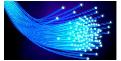
Figure 2: Optical Fibre
CONSTRUCTION OF OPTICAL FIBRE
It consists of a very thin fibre of silica or glass or plastic of a high refractive index called the core. The core has a diameter of 10 um to 100 um. The core is enclosed by a cover of glass or plastic called cladding. The refractive index of the cladding is less than that of the core (which is a must condition for the working of the optical fibre). The difference between the two indicates is very small of order 10-3. The core and the cladding are enclosed in an outer protective jacket made of plastic to provide strength to the optical fibre. The refractive index can change from core to cladding abruptly (as in step-index fibre) or gradually (as in graded-index fibre).
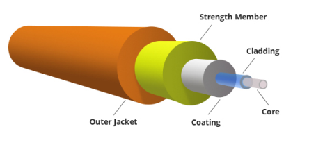
Figure 3: Representation of Optical Fibre
WORKING OF OPTICAL FIBRE
When a ray of light is incident on the core of the optical fibre at a small angle, it suffers refraction and strikes the core-cladding interface, As the diameter of the fibre is very small hence the angle of incidence is greater than the critical angle. Therefore, the ray suffers total internal reflection at the core-cladding interface and strikes the opposite interface. At this interface also, the angle of incidence is greater than the critical angle, so it again suffers total internal reflection. Thus, the ray of light reaches the other end of the fibre after suffering repeated total internal reflections along the length of the fibre. At the other end, the ray suffers refraction and emerges out of the optical fibre.
We can see that the light travels in the core in a guided manner. Hence the communication through the optical fibre is sometimes referred to as an optical waveguide.
OPTICAL FIBRE AS A DIELECTRIC WAVE GUIDE
Light propagates inside an optical fiber by virtue of multiple TIRs at the core-cladding interface. The refractive index of the core glass is greater than that of the cladding. This meets the first condition for a TIR. All the light energy that is launched into the optical fiber through its tip does not get guided along the fiber. Only those light rays propagate through the fiber which is launched into the fiber at such an angle that the refracted ray inside the core of the optical fiber is incident on the core-cladding interface at an angle greater than the critical angle of the core with respect to the cladding.
1. Optical fiber is basically a solid glass rod. The diameter of rod is so small that it looks like a fiber.
2. Optical fiber is a dielectric waveguide. The light travels like an electromagnetic wave inside the waveguide. The dielectric waveguide is different from a metallic waveguide which is used at microwave and millimeter wave frequencies.
3. In a metallic waveguide, there is a complete shielding of electromagnetic radiation but in an optical fiber the electromagnetic radiation is not just confined inside the fiber but also extends outside the fiber.
4. The light gets guided inside the structure, through the basic phenomenon of total internal reflection.
5. The optical fiber consists of two concentric cylinders; the inside solid cylinder is called the core and the surrounding shell is called the cladding. (See Fig 12)
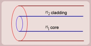
Figure 4: Schematic of an optical fiber
6. For the light to propagate inside the fiber through total internal reflections at core-cladding interface, the refractive index of the core must be greater than the refractive index of the cladding. That is n1>n2.
SIMPLE RAY MODEL

Figure 5: (optical fiber with core, cladding and total internally reflected ray)
For propagation of light inside the core there are two possibilities.
1. A light ray is launched in a plane containing the axis of the fiber. We can then see the light ray after total internal reflection travels in the same plane i.e., the ray is confined to the plane in which it was launched and never leave the plane. In this situation the rays will always cross the axis of the fiber. These are called the Meridional rays.
2. The other possibility is that the ray is not launched in a plane containing the axis of the fiber.
For example if the ray is launched at some angle such that it does not intersect the axis of the fiber, then after total internal reflection it will go to some other plane. We can see that in this situation the ray will never intersect the axis of the fiber. The ray essentially will spiral around the axis of fiber. These rays are called the Skew rays.
So it can be concluded that if the light is to propagate inside an optical fiber it could be through two types of rays
a) Meridional rays: The rays which always pass through the axis of fiber giving high optical intensity at the center of the core of the fiber.
b) Skew Rays: The rays which never intersect the axis of the fiber, giving low optical intensity at the center and high intensity towards the rim of the fiber.
Propagation of Meridional Rays

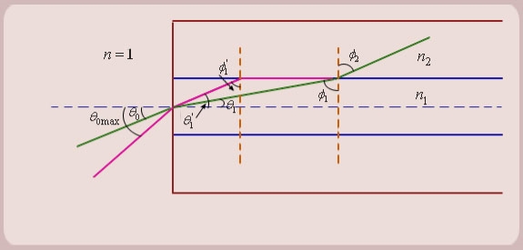
Figure 6: Propagation of Meridional Rays
- Let us consider figure 6. A ray is launched from outside (air) at an angle θ0 , from the axis of the fiber.
The question is, under what conditions the ray is ultimately guided inside the core due to total internal reflections at the core cladding boundary.
2. Let the ray makes an angle θ1 with the axis of the fiber inside the core, and let the ray make an angle ϕ1 with core -cladding interface. Let ϕ2 be the angle of refraction in the cladding.
If ϕ1 < critical angle the ray is refracted in cladding. The ray which goes to cladding is lost and is not useful for communication. The ray which is confined to the core is useful for optical communication.
3. Now as we increase the launching angle θ0, the angle θ1 also increases. Since θ1 + ϕ1 = 
ϕ1 decreases and at some point becomes less than the critical angle. When ϕ1 equals the critical angle, ϕ2 equals  . The maximum launching angle then corresponds to ϕ2 =
 .
.
4. Let us apply Snell’s law at the launching point and at the core-cladding interface for the maximum launching angle θ0max. For this case let θ1 = θ’1 and ϕ1 = ϕ’1
We then have
 (since
  )
)

Now,

So the sine of the maximum angle at which the ray will be guided inside the fiber is given by square root of the difference of squares of the refractive indices of the core and cladding. The quantity is called the numerical aperture of an optical fiber. The NA is a measure of the power launching efficiently of an optical fiber.
Key Takeaways
- A cable that is used to transmit the data through fibres (threads) or plastic (glass) is known as an optical fibre cable. This cable includes a pack of glass threads that transmits modulated messages over light waves.
- Principle: Optical Fibre works on the principle of Total Internal Reflection.
- It consists of a very thin fibre of silica or glass or plastic of a high refractive index called the core. The core has a diameter of 10 um to 100 um.
- The core is enclosed by a cover of glass or plastic called cladding. The refractive index of the cladding is less than that of the core.
- The core and the cladding are enclosed in an outer protective jacket made of plastic to provide strength to the optical fibre.
- Light propagates inside an optical fiber by virtue of multiple TIRs at the core-cladding interface.
- The refractive index of the core glass is greater than that of the cladding.
- Optical fiber is a dielectric waveguide. The light travels like an electromagnetic wave inside the waveguide.
- If the light is to propagate inside an optical fiber it could be through two types of rays; Meridional rays and Skew Rays.
- The quantity
 is called the numerical aperture of an optical fiber. The NA is a measure of the power launching efficiently of an optical fiber. It is given by NA = ( n12- n22 )1/2
ACCEPTANCE ANGLE
Definition:- Acceptance angle is defined as the maximum angle of incidence at the interface of air medium and core medium for which the light ray enters into the core and travels along with the interface of core and cladding.
Let n0 be the refractive indices of air
n1 be the refractive indices of core
n2 be the refractive indices of cladding
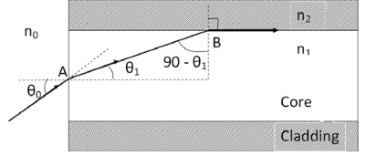
Figure 7: Acceptance angle
Let a light ray OA is an incident on the interface of air medium and core medium with an angle of incidence θ0
The light ray refracts into the core medium with an angle of refraction θ1 and the refracted ray AB is again incident on the interface of core and cladding with an angle of the incident (90- θ1)
If (90- θ1) is equal to the critical angle of core and cladding media then the ray travels along with the interface of core and cladding along the path BC. If the angle of the incident at the interface of air and core θ1< θ0 then (90- θ1) will be greater than the critical angle. Therefore,
The total internal reflection takes place.
According to Snell’s law at point A
n0 Sin θ0 = n1 Sin θ1
Sin θ0= (n1 / n0) Sin θ1 ………(1)
According to Snell’s law at point B
n1 Sin(90- θ1) = n2 Sin90 ………(2)
n1 Cosθ1 = n2 as (Sin90=1)
Cosθ1 = n2 /n1
Sinθ1 = (1-Cos2 θ1)1/2
Sinθ1= (1- (n2 /n1)2)1/2
Sinθ1= ( n12- n22 )1/2/ n1 ………(3)
We know Sin θ0= (n1 / n0) Sin θ1 from equation (1)
Substitute the value of Sinθ1 from equation (3)
Sinθ0= (n1 / n0) *( n12- n22 )1/2/ n1
On simplification
Sinθ0= ( n12- n22 )1/2/ n0
θ0=Sin-1 ( n12- n22 )1/2/ n0
Acceptance Angle is θ0=Sin-1 ( n12- n22 )1/2/ n0 ………(4)
ACCEPTANCE CONE
Acceptance angle is the maximum angle that a light ray can have relative to the axis of the fibre and propagate down the fibre. Thus, only those rays that are incident on the face of the fibre making angles less than θ0 will undergo repeated total internal reflections and reach the other end of the fibre. Hence, larger acceptance angles make it easier to launch light into fibre.
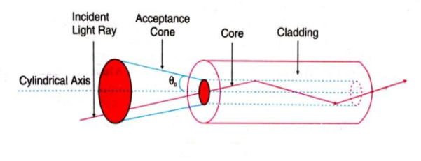
Figure 8: Acceptance cone
In three dimensions, the light rays contained within the cone having a full angle 2θ0 are accepted and transmitted along with the fibre as shown in figure 8. Therefore, the cone is called the acceptance cone. Light incident at an angle beyond θ0 refracts through the cladding and corresponding optical energy is lost.
NUMERICAL APERTURE
Definition: -Numerical aperture is defined as the light gathering capacity of an optical fibre and it is directly proportional to the acceptance angle. Numerically it is equal to the sin of the acceptance angle.
NA = Sin(acceptance angle)
NA = Sin {Sin-1 (( n12- n22 )1/2/ n0)} from equation (4)
NA = (( n12- n22 )1/2/ n0) ………(5)
If the refractive index of the air medium is unity i.e. n0=1 put in (5)
NA = ( n12- n22 )1/2 ………(6)
Fractional change in refractive index
∆= (n1- n2)/ n1
n1∆ = (n1- n2) ………(7)
From equation (6), we have
NA = {( n1- n2 )( n1+n2 )}1/2
NA = { n1∆ (n1+n2 )}1/2 as n1∆ = (n1- n2) by Eq(7)
NA = { n1∆ 2n1}1/2 n1 ≈ n2, so n1+n2 =2n1
NA = n1{2∆}1/2
This gives the relation between Numerical aperture and Fractional change in refractive index.
Key Takeaways
- Acceptance angle is defined as the maximum angle of incidence at the interface of air medium and core medium for which the light ray enters into the core and travels along with the interface of core and cladding.
- Acceptance Angle is given by θ0=Sin-1 ( n12- n22 )1/2/ n0
- In three dimensions, the light rays contained within the cone having a full angle 2θ0 are accepted and transmitted along with the fibre. Therefore, the cone is called the acceptance cone.
- Numerical aperture is defined as the light gathering capacity of an optical fibre and it is directly proportional to the acceptance angle. Numerically it is equal to the sin of the acceptance angle.
- Numerical aperture is given by NA = n1{2∆}1/2
7.3.1 CLASSIFICATION OF OPTICAL FIBERS- SINGLE MODE AND MULTI-MODE FIBER, STEP INDEX AND GRADED INDEX FIBERS,
The types of optical fibres depend on the refractive index, materials used, and mode of propagation of light.
The classification based on the materials used is as follows:
- Plastic Optical Fibres: The polymethylmethacrylate is used as a core material for the transmission of light.
Example:
Core: polymethyl methacrylate : Cladding: Co- Polymer
Core: Polystyrene : Cladding: Methyl methacrylate
- Glass Fibres: It consists of extremely fine glass fibres.
Example:
Core: SiO2 Cladding: SiO2
Core: GeO2- SiO2 Cladding: SiO2
- The classification based on the mode of propagation of light is as follows:
Mode of propagation:
Light propagates as electromagnetic waves through an optical fibre. All waves, having ray directions above the critical angle will be trapped within the fibre due to total internal reflection. However, all such waves do not propagate through the fibre. Only certain ray directions are allowed to propagate. The allowed directions correspond to the modes of the fibre. In simple terms, modes can be visualized as the possible number of paths of light in an optical fibre.
- Single-Mode Fibres:
These fibres are used for long-distance transmission of signals. In general, the single-mode fibres are step-index fibres. These types of fibres are made from doped silica. It has a very small core diameter so that it can allow only one mode of propagation and hence called single-mode fibres.
The cladding diameter must be very large compared to the core diameter. Thus in the case of single-mode fibre, the optical loss is very much reduced. The structure of a single-mode fibre is given below.
Structure:
Core diameter: 5-10μm
Cladding diameter: Generally around 125μm
Protective layer: 250 to 1000μm
Numerical aperture: 0.08 to 0.10
Bandwidth: More than 50MHz km.
Application:
Because of high bandwidth, they are used in long-haul communication systems.
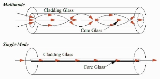
Figure 8: Single Mode and Multimode Fibre
- Multimode Fibres:
These fibres are used for short-distance transmission of signals. The multi-mode fibres are useful in manufacturing both for step-index and graded-index fibres. The multi-mode fibres are made by multi-component glass compounds such as Glass – Clad Glass, Silica – Clad – Silica, doped silica, etc. Here the core diameter is very large compared to single-mode fibres, so that it can allow many modes to propagate through it and hence called Multi-mode fibres. The cladding diameter is also larger than the diameter of the single-mode fibres. The structure of the multimode fibre is as shown in the figure above.
Structure:
Core diameter : 50-350μm
Cladding diameter : 125μm - 500μm
Protective layer : 250 to 1100μm
Numerical aperture : 0.12 to 0.5
Bandwidth : Less than 50MHz km.
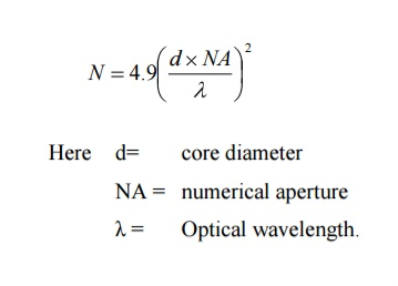
The total number of modes possible for such an electromagnetic waveguide is
Application:
Because of its less bandwidth, it is very useful in short-haul communication systems.
- The classification based on the refractive index is as follows:
- Step Index Single-mode Fibres
It consists of a core surrounded by the cladding, which has a single uniform index of refraction. Step index-single mode fibres: A single-mode step-index fibre consists of a very thin core of uniform refractive index surrounded by a cladding of refractive index lower than that of the core. The refractive index abruptly changes at the core-cladding boundary. Light travels along a side path, i.e., along the axis only. So zero-order modes are supported by Single Mode Fibre.
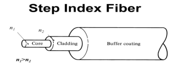
Figure 9: Step Index Single-mode Fibres
- Step index-Multimode fibres
A multimode step-index fibre consists of a core of uniform refractive index surrounded by a cladding of refractive index lower than that of the core. The refractive index abruptly changes at the core-cladding boundary. The core is of large diameter. Light follows zigzag paths inside the fibre. Many such zigzag paths of propagation are permitted in Multi-Mode Fibre. The Numerical Aperture of a Multi-mode fibre is larger as the core diameter of the fibre is larger
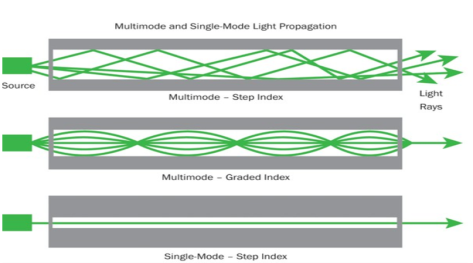
Figure 10: Step index-Multimode fibres
- Graded Index Fibres:
The refractive index of the optical fibre decreases as the radial distance from the fibre axis increases. GRIN fibre is one in which the refractive index varies radially, decreasing continuously in a parabolic manner from the maximum value of n1, at the center of the core to a constant value of n2 at the core-cladding interface.
In graded-index fibre, light rays travel at different speeds in different parts of the fibre because the refractive index varies throughout the fibre. Near the outer edge, the refractive index is lower. As a result, rays near the outer edge travel faster than the rays at the center of the core. Because of this, rays arrive at the end of the fibre at approximately the same time. In effect light rays that arrive at the end of the fibre are continuously refocused as they travel down the fibre. All rays take the same amount of time in traversing the fibre. This leads to small pulse dispersion.
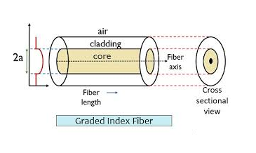
Figure 11: Graded Index Fibres

For a parabolic index fibre, the pulse dispersion is reduced by a factor of about 200 in comparison to step-index fibre. It is because of this reason that first and second-generation optical communication systems used near parabolic index fibres.
Key Takeaways
- The types of optical fibres depend on the refractive index, materials used, and mode of propagation of light.
- The classification based on the materials is of two type plastic optical fibres and glass fibres.
- The classification based on the mode of propagation is of two type single mode fibre and multimode fibre.
- The classification based on the refractive index is of three types step index single mode fibre, step index multimode fibre and graded index fibre.
7.3.2 ADVANTAGES OF OPTICAL FIBERS OVER CONDUCTING WIRES
Let us discuss in detail the advantages of fibre optic communication
Optical fibre communication has more advantages than conventional communication.
1. Enormous Bandwidth
2. Low Transmission Loss
3. Electric Isolation
4. Signal Security
5. Small Size and Less Weight
6. Immunity Cross Talk
1. Enormous bandwidth:- The information-carrying capacity of a transmission system is directly proportional to the frequency of the transmitted signals. In the coaxial cable transmission, the bandwidth range is up to around 500MHz only. Whereas in optical fibre communication, the bandwidth range is large as 105 GHz.
2. Low transmission loss:- The transmission loss is very low in optical fibres (i.e.KmdB/2.0) than compare with the conventional communication system. Hence for long-distance communication fibres are preferred.
3. Electric isolation:- Since fibre optic materials are insulators, they do not exhibit earth and interface problems. Hence communicate through fibre even in an electrical dangerous environment.
4. Signal security:- The transmitted signal through the fibre does not radiate, unlike the copper cables, a transmitted signal cannot be drawn from fibre without tampering with it. Thus the optical fibre communication provides 100% signal security.
5. Small size and less weight:- The size of the fibre ranges from 10μm to 50μm, which is very small. The space occupied by the fibre cable is negligibly small compared to conventional electrical cables. Optical fibres are light in weight.
6. Immunity cross-talk:- Since the optical fibres are dielectric waveguides, they are free from any electromagnetic interference and radio frequency interference. Since optical interference among different fibres is not possible, cross talk is negligible even many fibres are cabled together.
Disadvantages of Optical Fibre
The disadvantages of optical fibre include the following
- The main disadvantages of these cables are installation is expensive and difficult to fix together.
- The optical fibre cables are very difficult to merge & there will be a loss of the beam within the cable while scattering.
- Fibre optic cables are compact and highly vulnerable while fitting
- These cables are more delicate than copper wires.
- Special devices are needed to check the transmission of fibre cables.
Application
- Optical fibres are extensively used in a communication system.
- Optical fibres are in the exchange of information between different computers
- Optical fibres are used for the exchange of information in cable televisions, space vehicles, submarines, etc.
- Optical fibres are used in the industry in security alarm systems, process control, and industrial auto machine.
- Optical fibres are used in pressure sensors in biomedical and engine control.
- Optical fibres are used in medicine, in the fabrication of endoscopy for the visualization of internal parts of the human body.
- Sensing applications of optical fibres are Displacement sensor, Fluid level detector, Liquid level sensor, Temperature/pressure sensor, and Chemical sensors
- Medical applications of optical fibres are Gastroscopy, Orthoscopic, Couldoscope, Peritonescope, and Fibrescope.
Q 1) The refractive indices of core and cladding materials of a step index fibre are 1.48 and 1.45, respectively. Calculate numerical aperture?
A 1)
Let the refractive index of core, n1 = 1.48
And the refractive index of cladding , n2 = 1.45
Numerical aperture (NA) 

Q 2) A step-index fiber has a core index of refraction of n1 = 1.425. The cut-off angle for light entering the fiber from air is found to be 8.50o. (a) What is the numerical aperture of the fiber? (b) What is the index of refraction of the cladding of this fiber? (c) If the fiber were submersed in water, what would be the new numerical aperture and cut-off angle?
A 2)
(a) we know that n0 = nair = 1.0003. The numerical aperture is therefore
NA = n0 sin θ0max = (1.0003) sin (8.50o) = 0.148.
(b) The index of refraction of the cladding can be found from the numerical aperture:
n12 - n22 = NA2.
n22 = n12 - NA2 = (1.425)2 - (0.1479)2 = 2.0088
n2 = 1.417.
(c) We know that that the n0 = nwater = 1.33. Since the numerical aperture is a property of the fiber and only depends upon n1 and n2, it will not change when the medium outside the fiber changes. The cut-off angle, however, will have to change if the numerical aperture is to be unaffected by a change in n0:
NA = 0.148.
sin θ0max = NA/n0
θ0max = sin-1(NA/n0) = sin-1(0.1479/1.33) = = sin-1(0.1112) = 6.38o.
Q 3) Let n = 1, n1 = 1.46 and n2 = 1.45 in the diagram of the optical fiber system
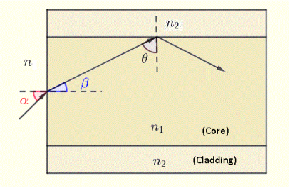
Figure 12: optical fiber
Find
a) the critical angle θc at the core - cladding interface.
b) the numerical aperture N.A. Of the optical fiber
c) the angle of acceptance αmax of the the optical fiber system.
A 3)
a) θc = sin-1 (n2 / n1) = sin-1 (1.45 / 1.46) = 83.29 °
b) N.A. = √(n21 - n22) = √(1.462 - 1.452) = 0.17
c) αmax = sin-1√(1.462 - 1.452) = 9.82 °
Q 4) Let n = 1, n1 = 1.46 and n2 = 1.45 in the diagram of the optical fiber
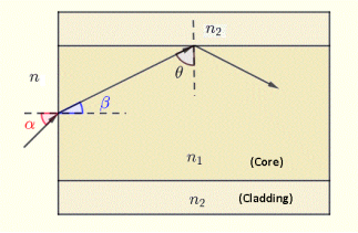
Figure 13: optical fiber
The angle of incidence of a light ray on the outside - core interface be α = 5°. Find
a) angle of refraction β at the outside - core interface.
b) angle θ
c) and explain why this light ray will be reflected at the core - cladding interface and hence guided along the fiber.
A 4)
a) Angle β is found using Snell's law at the outside - core interface as follows
n sin(α) = n1 sin(β)
Substitute the given parameters from Q 3) to obtain
β = sin-1 ( sin(5°) / n1) = 3.42 °
b) Angle θ is complementary to angle β hence
θ = 90 - 3.42 = 86.58 °
c) The angle of incidence θ = 86.58 ° at the core - cladding interface is larger that the critical angle θc = 83.29 ° calculated in Q 3) above and will therefore be totally reflected at this interface and hence guided along the fiber.
Also angle α = 5° is smaller to αmax = 9.82 °
Reference
- Fundamentals of optics-Jenkins and White. McGraw Hill Publication
- A Text Book of Optics Subrahmanyam, BrijIal, S. Chand Publication
- Optics by Ajay Ghatak
- Engineering physics - Avadhanalu and Kshirsagar, S.Chand Publication