UNIT 1
DC Circuits
1.1.1. Ohm’s Law
Statement - Ohm’s Law states that the current flowing through a conductor is directly proportional to the potential difference applied across its ends, provided the temperature and other physical conditions remain unchanged. Mathematically it can be represented as,
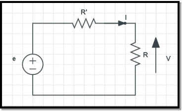
Potential difference ∝ Current
V ∝ I
(When the value of V increases the value of I increases simultaneously)
V = IR ………………………. (eq.1)
Where,
- V is Voltage in volts (V)
- R is Resistance in ohm (Ω)
- I is Current in Ampere (A)
Calculating Various Parameters Using Ohm’s Law
As an equation (eq.1), the Ohm’s Law serves as master for calculating the current (I), when the resistance (R) and the potential difference (V) are known. Similarly, if any two parameters in the equation (eq.1) are known, then the unknown third one can be easily calculated as follows:
- To find Voltage(V),
V = IR …………………………… (eq.2)
- To find Current(I),
I=VR ……………………………… (eq.3)
- To find Resistance(R),
R=VI ……………………………… (eq.4)
1.1.2. Resistance
Resistance is a opposition offered to the current flowing in any electrical circuit. It is measure in terms of ohms, which is symbolized by the Greek letter omega (Ω)
From the definition, it can be said that the unit of electric resistance is volt per ampere.
One unit of resistance is such a resistance which causes 1 ampere current to flow through it when 1 volt potential difference is applied across the resistance.
The unit of electric resistance is volt per ampere which is called as ohm(Ω) after the name of great German physicist George Simon Ohm.
1.1.3.Specific Resistance
The resistance offered per unit length and unit cross-sectional area when a known amount of voltage is applied is called as Specific resistance.SI unit of specific resistance is ohm meter (Ωm).
The mathematical representation is -
ρ=R(A/L)
Where,
⍴: specific resistance
R: resistance
A: cross-sectional area
L: length of the material
1.1.4. Energy Sources
Electrical energy can be produced by converting different energies available in nature.Natural sources of energy which is used to produce electricity are-
- The Sun
- The Wind
- The Water Head
- The Fuel
- The Nuclear Energy
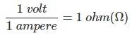
1.1.5. Concepts Of Open Circuit And Short Circuit
An open circuit implies that the two terminals are points are externally disconnected(open), which is equivalent to a resistance R=∞ . This means that zero current can flow between the two terminals, regardless of any voltage difference.
A short circuit implies that the two terminals are externally connected with resistance R=0 , the same as an ideal wire. This means there is zero voltage difference for any current value.
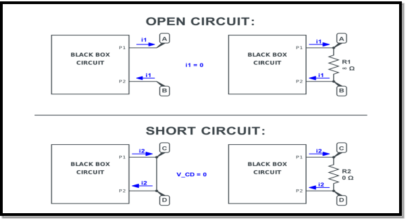
The algebraic sum of currents meeting at a junction or node in an electric circuit is zero ② or the summation of all incoming currents is always equal to the summation of all outgoing current in an electrical network.
Explanation
Assuming the incoming current to be positive and outgoing current negative we have


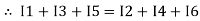
Ie incoming current = ∑ outgoing current thus, the above Law can also be stated as the sum of current flowing towards any junction in an electric circuit is equal to the sum of currents flowing away from that junction
Kirchhoff’s Voltage Law (KVL)
Statement: the algebraic summation of all Voltage in any closed circuit or mesh of loop zero.
i.e. ∑ Voltage in closed-loop = 0 the summation of the Voltage rise (voltage sources) is equal to the summation of the voltage drops around a closed loop in 0 circuits for an explanation from here determination of sigh and direction of currents (Don’t write in exams just for understanding)
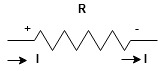
Current entering a resistor is +ve and leaving should be –ve
Now
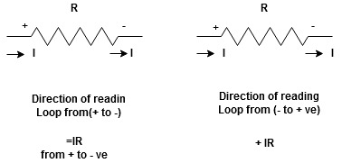


Potential Rise Potential Drop
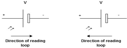
We are reading from +V to –V we are reading from –V to +V
 potential drops
  potential rise
 -V
-V  +V
+V
Given Circuit
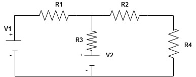
First, identify no of loops and assign the direction of current flowing in the loop
Note: no of loops in-circuit = No, of unknown currents = no, of equations in the circuit
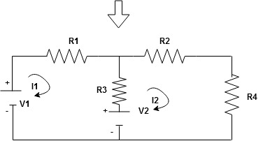
Note: keep loop direction and current direction same ie either clockwise or anticlockwise for all loops I1 I2
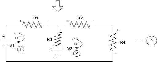
Now according to the direction of direction assign signs (+ve to –ve) to the resistors
Note: voltage sources (V) polarities do not change is constant.
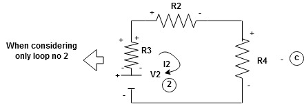
Note: for common resistor between 2 loops appearing in the circuit like R3 give signs according to separate loops as shown
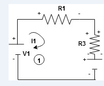
When considering only loop no 1 (+ R3 - )
- B
Now consider diagram A and write equations
Two loops  two unknown currents
  two-equation
Apply KVL for loop ① [B. Diagram ]
(+ to drop -) = - sign and (- to rise +) = + sign
 for drop = -sign
 for rise = + sign
-
-( ) R2 is considered because in R3,2 currents are flowing
  and
and  and we have taken (
 ) because we are considering loop no 1 and current flowing is
  in the loop no 1
 )
)
Similarly for loop no. 2 currents flowing is 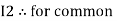 resistor R3 it should be
  )R3
)R3
Consider loop no. 1 apply KVL
- …….①
…….①
-
Consider loop no. 2 apply KVL
- …….②
…….②
-
After solving equation ① and ② we will get branch current  and
and 
Series and parallel circuit
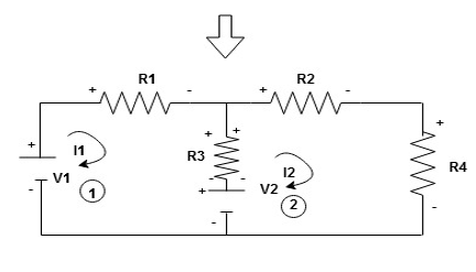
The basic idea of a “series” connection is that components are connected end-to-end in a line to form a single path through which current can flow:
Series connection
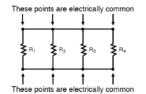
Parallel connection:
The basic idea of a “parallel” connection, on the other hand, is that all components are connected across each other’s leads. In a purely parallel circuit, there are never more than two sets of electrically common points, no matter how many components are connected. There are many paths for current flow, but only one voltage across all components:
Current and voltage division rule
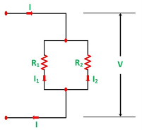
A parallel circuit acts as a current divider as the current divides in all the branches in a parallel circuit, and the voltage remains the same across them. The current division rule determines the current across the circuit impedance. The current division is explained with the help of the circuit shown below:
The current I has been divided into I1 and I2 into two parallel branches with the resistance R1 and R2 and V is the voltage drop across the resistance R1 and R2.
As we know,
V = IR ……..(1)
Then the equation of the current is written as:
I1 = V/R1 and I2 = V /R2
Let the total resistance of the circuit be R and is given by the equation shown below:
R = R1R2/ R1 + R2
Equation (1) can also be written as:
I = V/R ……….(3)
Now, putting the value of R from the equation (2) in the equation (3) we will get
I = V(R1+R2)/ R1R2 ---------------------------(4)
But
V = I1 R1 = I2 R2 ------------------------------(5)
Putting the value of V = I1R1 from the equation (5) in equation (4), we finally get the equation as:
I = I1R1(R1+R2)/ R1R2 = I1(R1+R2)/ R2---------------------(6)
And now considering V = I2R2 the equation will be:
I = I2R2(R1+R2)/ R1R2 = I1/R1 (R1+R2) ------------------------------(7)
Thus, from the equation (6) and (7) the value of the current I1 and I2 respectively is given by the equation below:
I1 + I . R2/ R1 + R2 and I2 = I . R1 / R1 + R2
Thus, in the current division rule, it is said that the current in any of the parallel branches is equal to the ratio of opposite branch resistance to the total resistance, multiplied by the total current.
Voltage Division Rule
The voltage division rule can be understood by considering a series circuit shown below. In a series circuit, voltage is divided, whereas the current remains the same.
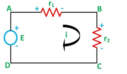
Let us consider a voltage source E with the resistance r1 and r2 connected in series across it.
As we know,
I = V/R or we can say I = E/R
Therefore, the current (i) in the loop ABCD will be:
i = E / r1 + r2 -------------------------(8)
And r1 = ir1
By putting the value of I from equation (8) in equation (9) the voltage across the resistance r1 and r2 respectively are given by the equation shown below as:
E1 = Er1/r1 + r2 and E2 = E r2/ r1 + r2
Thus, the voltage across a resistor in a series circuit is equal to the value of that resistor times the total impressed voltage across the series elements divided by the total resistance of the series elements.
We know that (from delta to star conversion)
R1 =  …….①
…….①
R2 =  …..②
…..②
R1 =  ……③
……③
Multiply ① X ② L.H.S and R.H.S
R1 R2 = …….④ where
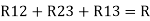
Similarly, multiply ② X ③
R2 R3 = …….⑤
…….⑤
And ③ X①
R1 R3 = …….⑥
…….⑥
Now add equation ④, ⑤, and ⑥ L.H.S and R.H.S

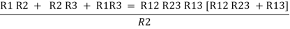
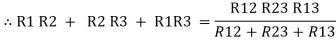
 ……refer eq. ②
 =
=  +
+  +
+ 
 =
=  +
+ 

(Delta) star star
Similarly, R23 = R2+R3 + 
R23 = R1+R2 + 
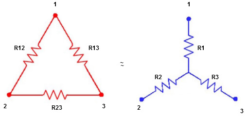
Delta to Star Conversion to Find (Req.)
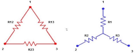
- Equivalent resistance between ① and ②
Delta  Star
Star
= R12// (R23 + R13) =R1 + R2
= 
 = R1 + R2
= 

Here let R = R12 + R23 + R13
- Similarly, we can find Req. Between 2 and 3
= 
 R2 + R3
- Similarly, we can find req. Between 1 and 3
 R1 + R3
Now the 3 equations after equating L.H.S. And R.H.S
R1 + R2 = 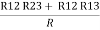 …….①
…….①
R2 + R3 = 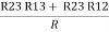 ……②
……②
R1 + R3 =  …..③
…..③
Now subtract ② and ① on L.H.S. And R.H.S
R2+ R3 – R1 – R2 = 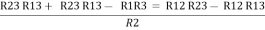
 R3 – R1 =
 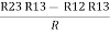 …..④
…..④
Now add equation ④ and ③
R3 – R1 + R1 + R3 = 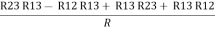
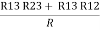
2R3 = 
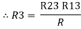
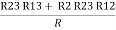
Similarly, R1 = 
And R2 = R23 R12/R where R = R12 + R23 + R13
i.e. star equivalent from delta network is the ratio of the product of adjacent branches in the delta to the addition of all branches in the delta.
References:
1. Electrical Technology (Volume I & 2), B L Thereja, 22nd edition, S Chand & Company Ltd
2. Basic Electrical Engineering, V K Mehta, Revised edition, S Chand & Company Ltd
3. Basic Electronics Solid State, B L Thereja, Revised edition, S Chand & Company Ltd
4. Digital Principles and Applications, Albert Malvino , Donald Leach, Tata McGraw Hills Publication
5. Principles of Electronic Devices and Circuits (Analog and Digital), B. L. Theraja , R. S. Sedha , S. Chand publication


