UNIT3
Single Phase AC Circuits
- Standard definitions related to AC Introductions
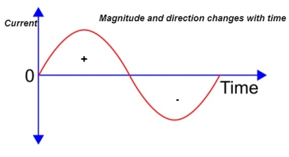
- Instantaneous value: The value of an alternating quantity at a particular instant is known as Instantaneous value.
- Waveform: The graph of Instantaneous values of an alternating quantity plotted against time.
- Cycle: each repetition of set of positive and negative Instantaneous value of an alternating quantity is called as cycle.
- Time period: The time taken by an alternating quantity to complete its on cycle known as time period.
- Frequency: The numbers of cycle completed by an alternating quantity per second known as Frequency.
Measured in cycle/second or that.
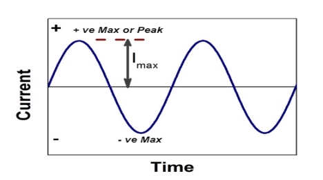
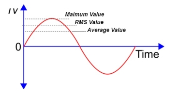
6. Amplitude: The maximum value attained by alternating quantity during positive or negative cycle is called as Amplitude.
7. Angular Frequency (w): it is the Frequency expressed in electrical radians per second w = 2 X F or w = 
8. Peat to peak value: the value of an alternating quantity from its positive peak to negative peak
- Equation of an alternating quantity
The alternating current can be
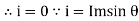
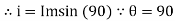
Expressed as i = Im Sin 
Im - max value
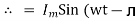
i = Im Sin wt
Where  = wt
= wt
Alternating voltage can be expressed as V = vm sin wt
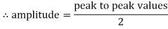
- RMS value: Root mean square value
The RMS value of AC current is equal to the steady state DC current that required to produce the same amount of heat produced by ac current provided that resistance and time for which these currents flows are identical.
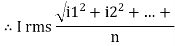
I rms = 
Direction for RMS value:
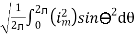
Instantaneous current equation is given by
i = Im Sin 
But 
I rms = 
= 
=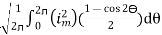
=
Solving
=
=
Similar we can derive
V rms=  or 0.707 Vm
 the RMS value of sinusoidally alternating current is 0.707 times the maximum value of alternating current
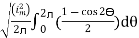
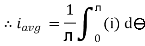
- Average Value:
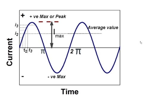
The arithmetic mean of all the value over complete one cycle is called as average value
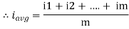
 =
= 
For the derivation we are considering only hall cycle.
Thus  varies from 0 to ᴫ
i = Im Sin
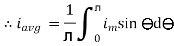
Solving
We get

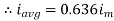
Similarly, Vavg=
The average value of sinusoid ally varying alternating current is 0.636 times maximum value of alternating current.
- Peak or krest factor (kp) (for numerical)
It is the ratio of maximum value to rms value of given alternating quantity
Kp = 
 Kp =
Kp = 
 Kp = 1.414
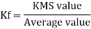
Form factor (Kf): For numerical “It is the ratio of RMS value to average value of given alternating quality”.


- Phases Representation of an Alternating Quantity
- The sinusoidal varying alternating quantity can be represented graphically by a straight line and arrow in the phase’s representation method.
- The length of the line represents magnitude and arrow indicates it direction.
- “The phases are assumed to be rotated in anticlockwise direction with constant Angular speed.”
- One complete cycle of sine wave is represented by one complete rotation of phases as shown below
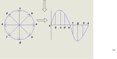
Consider at various position
- At point a the y axis projection is zero
 θ=0
θ=0 
- At point b the y axis projection 0b sin θ

- At point c the y axis projection (0C) represent max value of phase

2. Point D, y axis projection is (0ɖ)

3. At point e, y axis projection is zero

Now at point “ȴ” on words the phases change its direction  cycle also shifts from the half cycle to –v e half cycle.
3 Basic element of AC circuit.
1] Resistance
2] Inductance
3] Capacitance
Each element produces opposition to the flow of AC supply in a forward manner.
Reactance
- Inductive Reactance (XL)
It is opposition to the flow of an AC current offered by the inductor.
XL = ω L But ω = 2 ᴫ F
 XL = 2 ᴫ F L
It is measured in ohm
 XL∝ FInductor blocks AC supply and passes dc supply zero
2. Capacitive Reactance (Xc)
It is opposition to the flow of ac current offered by the capacitor
Xc = 
Measured in ohm
 Capacitor offers infinite opposition to dc supply
Impedance (Z)
The ac circuit is to always pure R pure L and pure C it well attains the combination of these elements. “The combination of R1 XL and XC is defined and called as impedance represented as
Z = R +i X
Ø = 0
 only magnitude
R = Resistance, i = denoted complex variable, X =Reactance XL or Xc
Polar Form
Z =  L I
L I
Where  =
=
 Measured in ohm
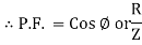
Power factor (P.F.)
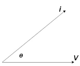
It is the cosine of the angle between voltage and current
If Ɵis –ve or lagging (I lags V) then lagging P.F.
If Ɵ is +ve or leading (I leads V) then leading P.F.
If Ɵ is 0 or in-phase (I and V in phase) then unity P.F.
Ac circuit containing pure resisting
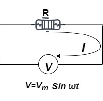
Consider Circuit Consisting pure resistance connected across the ac voltage source
V = Vm Sin ωt①
According to ohm’s law i =  =
= 
But Im = 
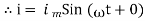 ②
②
From ① and ② phases or represents RMD value.
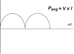
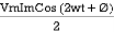
Power P = V. i
Equation P = Vm sin ω t Im sin ω t
P = VmIm Sin2 ω t
P =  -
- 

Constant fluctuating power if we integrate it becomes zero

Average power
Pavg = 
Pavg = 
Pavg = VrmsIrms
Power ware form [Resultant]
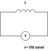
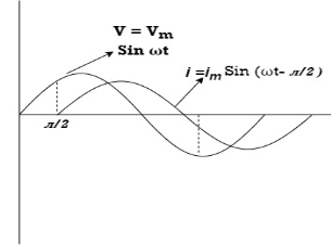
Ac circuit containing pure Inductors
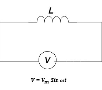
Consider pure Inductor (L) is connected across alternating voltage. Source
V = Vm Sin ωt
When an alternating current flow through inductance it setups alternating magnetic flux around the inductor.
This changing the flux links the coil and self-induced emf is produced
According to faradays Law of E M I
e = 
At all instant applied voltage V is equal and opposite to self-induced emf [ Lenz's law]
V = -e
 =
= 
But V = Vm Sin ωt
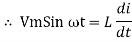
 dt
dt
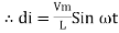
Taking integrating on both sides
 dt
dt
 dt
dt
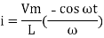
 (-cos
(-cos  )
)
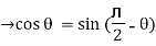
But sin (– ) = sin (+
 )
)
 sin (
sin ( -
-  /2)
/2)
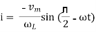
And Im= 
 /2)
/2)
 /2
/2
= -ve
= lagging
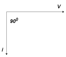
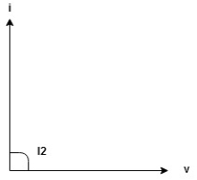
= I lag v by 900
Waveform:
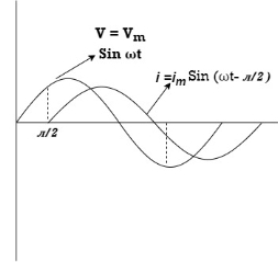
Phasor:
Power P = Ѵ. I
= Vm sin wtIm sin (wt /2)
/2)
= VmIm Sin wt Sin (wt –  /s)
/s)
 ①
①
And
Sin (wt -  /s) = - cos wt ②
Sin (wt –  ) = - cos
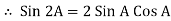
 sin 2 wt from ① and ②
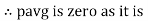
The average value of sin curve over a complete cycle is always zero
 Pavg = 0
Ac circuit containing pure capacitors:
Consider pure capacitor C is connected across an alternating voltage source
Ѵ = Ѵm Sin wt
Current is passing through capacitor the instantaneous charge ɡ produced on the plate of the capacitor
ɡ = C Ѵ
ɡ = c Vm sin wt
The current is the rate of flow of charge

i= (cvm sin wt)
i = c Vm w cos wt
Then rearranging the above eqth.
i =  cos wt

 = sin (wt +
  X/2)
X/2)
i =  sin (wt + X/2)
But 
 X/2)
X/2)

= leading
= I leads V by 900
Waveform :

Phase
Power P= Ѵ. i
= [Vmsinwt] [ Im sin (wt + X/2)]
= VmIm Sin wt Sin (wt + X/2)]
 (cos wt)
 to charging power waveform [resultant].
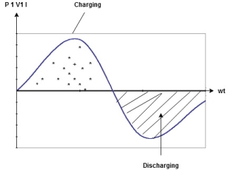
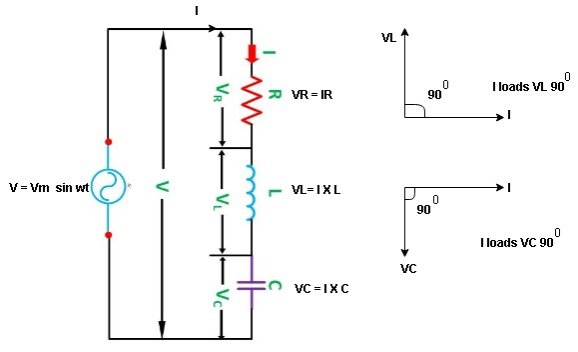
Series R-L Circuit
Consider a series R-L circuit connected across voltage source V= Vm sin wt
Like some, I is the current flowing through the resistor and inductor due do this current-voltage drops across R and L R  VR = IRand L
 VL = I X L
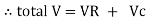
 Total V = VR + VL
V = IR + I X L  V = I [R + X L]


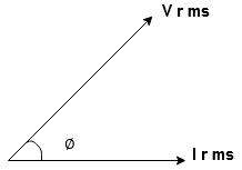
Take current as the reference phasor: 1) for resistor current is in phase with voltage 2) for Inductor voltage leads current or current lags voltage by 90 0.
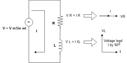
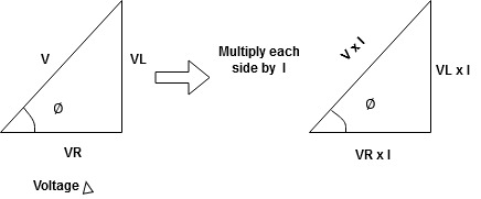
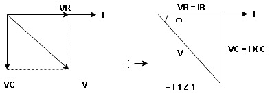
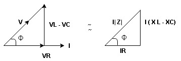
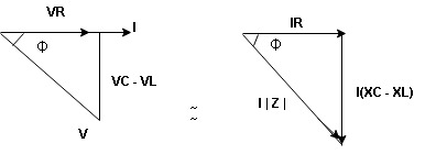
For voltage triangle
Ø is the power factor angle between current and resultant voltage V and
V = 
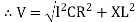
V = 

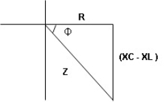
Where Z = Impedance of circuit and its value is  =
= 
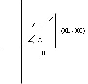
Impedance Triangle
Divide voltage triangle by I
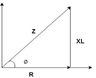
Rectangular form of Z = R+ixL
And polar from of Z =  L +
L + 
(+ j X L + because it is in first quadrant )
Where  =
= 
 + Tan -1
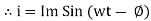
Current Equation :
From the voltage triangle, we can sec. That voltage is leading current by  or current is legging resultant voltage by
Or i =  =
=  [ current angles - Ø )
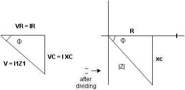
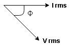
Resultant Phasor Diagram form Voltage and current eq.
Waveform

Power equation
P = V .I.
P = Vm Sin wtIm Sin wt – Ø
P = VmIm (Sin wt) Sin (wt – Ø)
P =  (Cos Ø) - Cos (2wt – Ø)
Since 2 sin A Sin B = Cos (A-B) – Cos (A+B)
P =  Cos Ø -
  Cos (2wt – Ø)

①②
Average Power
Pang =  Cos Ø
Cos Ø
Since ② term becomes zero because Integration of cosine come from 0 to 2ƛ
 pang = Vrms Irms cos Ø watts.
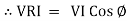
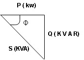
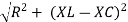
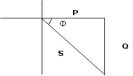
Power Triangle :
From 
VI = VRI + VLI B
Now cos Ø in  A =
A =
 ①
①
Similarly Sin  =
= 


Apparent Power Average or true Reactive or useless power
Or real or active
-Unit (VI) Unit (Watts) C/W (VAR) denoted by (Ø)
Denoted by [S] denoted by [P]
Power  for R L ekt.
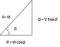
Series R-C circuit
V = Vm sin wt
VR

 I
I
- Consider a series R – C circuit in which resistor R is connected in series with capacitor C across an ac voltage so use V = VM Sin wt (voltage equation).
- Assume current I is flowing through
R and C  voltage drop across.
R and C  R
R  VR = IR
And C  Vc = I
 c
c
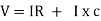

 V =
V =  lZl
lZl
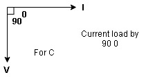
Voltage triangle: take current as the reference phasor 1) for resistor current is in phase with voltage 2) for capacitor current leads voltage or voltage lags behind current by 900
Where Ø is the power factor angle between current and voltage (resultant) V
And from voltage
V = 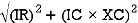
V = 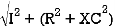
V = 
V =  lZl
lZl
Where Z = impedance of the circuit and its value is lZl = 
Impendence triangle :
Divide voltage  by
by  as shown
The rectangular form of Z = R - jXc
The polar form of Z = lZl L - Ø
( - Ø and –jXc because it is in the fourth quadrant ) where
LZl = 
And Ø = tan -1 
Current equation :
From voltage triangle we can see that voltage is lagging current by Ø or current is leading voltage by Ø
 i = IM Sin (wt + Ø) since Ø is +ve
Or i =  for RC
 LØ [ resultant current angle is + Ø]
Resultant phasor diagram from voltage and current equation
Resultant waveform :
Power Equation :
P = V. I
P = Vm sin wt. Im Sin (wt + Ø)
= VmIm sin wt sin (wt + Ø)
2 Sin A Sin B = Cos (A-B) – Cos (A+B)
 -
- 
Average power
Pang =  Cos Ø
Cos Ø
Since 2 terms integration of cosine wave from 0 to 2ƛ become zero
 2 terms become zero
 pang = Vrms Irms Cos Ø
Power triangle RC Circuit:
R-L-C series circuit
Consider ac voltage source V = Vm sin wt connected across the combination of R L and C. When I flowing in the circuit voltage drops across each component as shown below.
VR = IR, VL = I  L, VC = I
  C
C
- According to the values of Inductive and Capacitive Reactance, I e XL and XC decides the behavior of R-L-C series circuit according to following conditions
① XL> XC, ② XC> XL, ③ XL = XC
① XL > XC: Since we have assumed XL> XC
 The voltage drop across XL> than XC
 VL> VC A
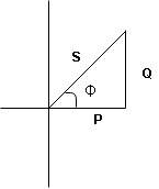
- Voltage triangle considering condition A

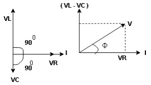
VL and VC are 180 0 out of phase.
Therefore cancel out each other
 Resultant voltage triangle
Now V = VR + VL + VC c phasor sum and VL and VC are directly in phase opposition and VL
 VC
VC their resultant is (VL - VC).
From voltage triangle
V = 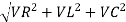
 V =
V = 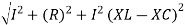
 V = I
V = I 

Impendence  : divide voltage
Rectangular form Z = R + j (XL – XC)
Polor form Z =  l + Ø B
Where  =
= 
And Ø = tan-1 
- Voltage equation : V = Vm Sin wt
- Current equation
i =  from B
i =  L-Ø C
L-Ø C
As VL VC the circuit is mostly inductive and
  I lags behind V by angle Ø
 Since i =
  L-Ø
L-Ø
 i = Im Sin (wt – Ø) from c
- XC
 XL :Since we have assured XC
  XL
XL
 the voltage drops across XC
  than XL
 XC
XC  XL (A)
 voltage triangle considering condition (A)
 Resultant Voltage
Now V = VR + VL + VC  phases sum and VL and VC are directly in phase opposition and VC
 VL
VL  their resultant is (VC – VL)
From voltage 
V = 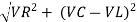
V = 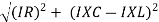
 V =
V = 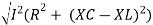
 V =
V = 

 Impedance
  : Divide voltage
- Rectangular form : Z + R – j (XC – XL) – 4thqurd
Polar form : Z =  L -
L -
Where 
And Ø = tan-1 – 
- Voltage equation : V = Vm Sin wt
- Current equation : i =
 from B
 - i =
 L+Ø C
L+Ø C
As VC  the circuit is mostly capacitive and
  leads voltage by angle Ø
Since i =  L + Ø
L + Ø
 Sin (wt – Ø) from C
- Power
 :
:
- XL= XC (resonance condition):
ɡȴ XL= XC then VL= VC and they are 1800 out of phase with each other  they will cancel out each other and their resultant will have zero value.
Hence resultant V = VR and it will be in phase with I as shown in the below phasor diagram.
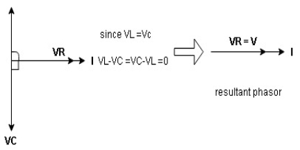
From the above resultant phasor diagram
V =VR + IR
Or V = I  lZl
lZl
Because lZl + R
Thus Impedance Z is purely resistive for XL = XC and circuit current will be in phase with source voltage.

 Since VR=V Øis zero when XL = XC
  power is unity
Ie pang = VrmsIrms cos Ø = 1 cos o = 1
Maximum power will be transferred by the condition. XL = XC
References:
1. Electrical Technology (Volume I & 2), B L Thereja, 22nd edition, S Chand & Company Ltd
2. Basic Electrical Engineering, V K Mehta, Revised edition, S Chand & Company Ltd
3. Basic Electronics Solid State, B L Thereja, Revised edition, S Chand & Company Ltd
4. Digital Principles and Applications, Albert Malvino , Donald Leach, Tata McGraw Hills Publication
5. Principles of Electronic Devices and Circuits (Analog and Digital), B. L. Theraja , R. S. Sedha , S. Chand publication


