UNIT -3
SOUND ENGINEERING
ACOUSTICS – ECHO
Acoustics, the science concerned with the production, control, transmission, reception, and effects of sound. The term is derived from the Greek akoustos, meaning heard.
In audio signal processing and acoustics, echo is a reflection of sound that arrives at the listener with a delay after the direct sound.. .. The delay is directly proportional to the distance of the reflecting surface from the source and the listener.
Echo is the sound of your voice reverberating in the telephone receiver while you are talking. If the echo’s amplitude is low, it goes unnoticed, and is not problematic in the conversation; however, if the echo interval exceeds approximately 25 milliseconds (ms), it becomes audible to the speaker. The echo can be extremely disruptive to a conversation. It can so critically impair voice quality that it makes phone calls very unpleasant and distracting; very often to the point of non-comprehension of the conversation. Most echo-laden telecom transactions are quickly abandoned by the participants.
Acoustic echo originates in a local audio loopback that occurs when a microphone(s), pick up audio signals from a speaker(s) and sends them back to an originating participant. The originating participant will then hear the echo of the participant’s voice as the participant speaks.
Acoustic echo can be intensified when sensitive microphone(s) are used, as well as when the microphone and/or speaker volume is turned up to a high level, and also when the microphone and speaker(s) are positioned so that the microphone is close to one or more of the speakers. This echo is aggravated by reflective acoustic echo reflected by walls and/or objects.
Acoustic echo is a common problem with audio conferencing systems. It originates in the local audio loop-back that occurs when your microphone picks up audio signals from your speaker and sends them back to the other participant along with your voice. The other participant hears this echo of his or her voice as he or she speaks.
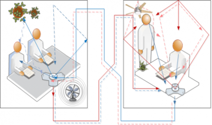
Figure 1: Acoustic echo: Local Loopback
Acoustic echo can be caused or exacerbated when very sensitive microphones are used, the speaker volume is turned up very high, or the microphone and speaker are very close to one another. Besides being annoying, this can prevent normal conversation among participants in a conference.
REVERBERATION AND REVERBERATION TIME
When a sound is produced in a building, it lasts too long after its production. It reaches the listener several times. Once it reaches directly from the source and subsequently after reflection from the walls, windows, ceiling, and flour of hall. The listener, therefore, receives a series of sounds of diminishing intensity. Reverberation is meant the prolonged reflection of sound from the walls, floor, and ceiling of a room.
The reverberation is defined as the persistence of audible sound after the source has stopped emitting sound. The duration for which the sound is stopped is called reverberation time. This time is measured from the instant the source stops the emitting sound.
The time of reverberation is defined as the time taken by the sound to fall below the minimum audibility measured from the instant when the source stopped emitting sound.
According to Prof. W. C. Sabine, the standard reverberation time is defined as the time taken by sound to fall to one-millionth of its intensity just before the sound is cut off.
ABSORPTION COEFFICIENT
The coefficient of absorption of the material is defined as the ratio of the sound energy absorbed by the surface to that of the total incident sound energy on the surface.
Absorption Coefficient = 
As all sound waves falling on an open window pass through, it can be assumed that an open window behaves as a perfect absorber of sound, and hence the standard of absorption is taken as the unit area of an open window as a standard unit of absorption.
Thus, the absorption coefficient of a material is defined as the rate of the sound energy absorbed by a certain area of the surface to that of the open window of the same area.
The absorption coefficient of a surface is defined as the reciprocal of its area which absorbs the same sound energy absorbed at a unit area of an open window.
SABINE's FORMULA FOR REVERBERATION TIME
According to W. C. Sabine, the time of reverberation depends upon
1. Size of the hall,
2. Loudness of the sound,
3. Kind of music or sound for which hall is to be used.
Acoustics and Ultrasonic Reverberation Time
T = 0.165 V/
T = 0.165 V/ A
Where V-Volume of the hall in m3
a - Absorption coefficient
S - Area of reflecting surface in a square meter
 Absorption of the hall.
BASIC REQUIREMENTS FOR ACOUSTICALLY GOOD HALL
Acoustics in architecture means improving sound in environments. Although it is a complex science, understanding the basics - and making efficient and effective decisions - is much easier than you might think. The first step is to understand that there are two technical categories used in acoustics: soundproofing and acoustical treatment. Soundproofing means "less noise" and acoustical treatment, "better sound”.
According to classic acoustics theory, there are five requirements which, when met, result in good acoustics:
- An appropriate reverberation time
- Uniform sound distribution
- An appropriate sound level
- An appropriately low background noise
- No echo or flutter echo
The acoustic requirement for a good auditorium is as follows-
- The initial sound should be of adequate intensity.
- The sound should be evenly distributed throughout the hall.
- The successive nodes should be clear & distinct.
- Noise has to be taken care of.
- The size & the shape of the ball have also to be taken care of.
These requirements can be achieved in the following ways-
Site/location:-Before construction the first important factor to be considered is the location. For the best acoustical quality of the hall, it should be far from railway tracks, industrial areas, airports, & highways, etc.
Size: - The size of the hall should be optimum, neither big nor small. Is the small uneven distribution of sound will take place due to the formations of stationary waves. If the size is too big reverberation time will be more that results in confusion & an unpleasant sound.
Shape: - Instead of parallel walls spade walls are preferred, curved surfaces should be built with proper care.
Reverberation: - Reverberation time (T) should be neither too small nor too large. If it is small intensity will be weak. If large sound will be unpleasant. Thick carpets curtains, upholstered chairs, audience take care of reverberation. For lecture halls, the reverberation time is approximately 0.5sec, for music concerts hall-1.5sec, for cinema theatres-2sec
Absorption: - Use of proper absorbent material enhances the quality of sound.
Echelon effect: - The regular intervals/space between staircase or railings give repeated echo, this makes the sound unpleasant, so thick carpets take care of this & wide gaps between staircases are generally preferred. No echo or flutter echoes must occur for the acoustics to be good. It is easy to prevent echo by installing a little sound-absorbing material on the wall.
Key Takeaways
- Acoustics, the science concerned with the production, control, transmission, reception, and effects of sound.
- Echo is a reflection of sound that arrives at the listener with a delay after the direct sound.
- The delay is directly proportional to the distance of the reflecting surface from the source and the listener.
- Acoustics in architecture means improving sound in environments.
- According to classic acoustics theory, there are five requirements such as an appropriate reverberation time, Uniform sound distribution, an appropriate sound level, an appropriately low background noise, No echo or flutter echo which, when met, result in good acoustics.
- Absorption Coefficient =

- According to W. C. Sabine, the time of reverberation depends upon Size of the hall, Loudness of the sound, Kind of music or sound for which hall is to be used.
Acoustical Materials
Acoustical materials are a variety of foams, fabrics, metals, etc. used to quiet workplaces, homes, automobiles, and so forth to increase the comfort and safety of their inhabitants by reducing noise generated both inside and outside of those spaces.
Acoustical materials are used in two major ways: as soundproofing, by which noise generated from outside a given space is blocked from entering the space; and, as sound-absorbing, where noise generated within a space is reduced inside the space itself.
As an example of soundproofing, a school might construct a special wall to isolate the music room from a general classroom next door. As for sound-absorbing, a machine shop might install barriers to block and absorb the acoustic energy of a noisy air compressor.
Sound and noise are managed by four methods: blocking, absorbing, diffusing, and isolating.
- Blocking relates to the use of soundproofing.
- Absorption works by converting sound energy into heat.
- Diffusion seeks to scatter sound without deadening a room.
- Isolating is done at the source of the noise itself, by placing a compressor on isolation mounts, for instance.
ACOUSTICAL DESIGN OF A HALL
Factors affecting the acoustics of buildings and their remedies
The acoustically good hall we mean that in which every syllable or musical note reaches an audible level of loudness at every point of the hall and then quickly dies away to make the room ready for the next syllable or group of notes. Following are the factors affecting architectural acoustics.
- REVERBERATION
In a hall, if the reverberation is large there are successive sounds that result in loss of clarity in hearing. However, if the reverberation is very small, the loudness is inadequate Thus the time of reverberation for a hall should neither too large nor too small. The preferred value of the time of reverberation is called optimum reverberation time. According to W. C. Sabine standard reverberation time is given by:
T = 0.165 V/
T = 0.165 V/ A
Where V-Volume of the hall in m3
a - Absorption coefficient
S - Area of reflecting surface in a square meter
 Absorption of hall
The reverberation can be controlled by the following factors:
- By providing windows and ventilators which can be opened and closed to make the optimum time of reverberation
- Decorating the walls with pictures and maps
- Using heavy curtains with folds
- The walls are lined with absorbent material such as felt, fibreboard, glass wool, etc.
- Having a full capacity of audience
- By covering the floor with carpet
- By providing acoustics tiles
2. ADEQUATE LOUDNESS
With large absorption, the time of reverberation will be smaller which will minimize the chances of confusion and may go below the level of intelligibility of hearing. Hence sufficient loudness in every portion of the hall is an important factor for satisfactory hearing.
The loudness can be maintained at the desired level by:
Using large sounding boards behind the speaker and facing the audience.
Large polished wooden reflecting surfaces immediately above the speakers.
Low ceilings are also useful in reflecting the sound energy towards the audience.
By providing additional sound energy using more number of speakers
3. FOCUSING DUE TO WALLS AND CEILINGS
If there are focusing surfaces like concave, spherical, cylindrical or parabolic, etc. on the walls or ceiling or the floor of the hall, they produce a concentration of the sound into a particular region, while in some other parts no sound reaches at all. Thus there will be non- uniformity in the distribution of sound energy in the hall.
For uniform distribution of sound in the hall:
- There should be no curved surfaces. If such surfaces are present, they should be covered with absorbent material.
- The ceiling should be low.
- Arrange speaker at the focus of parabolic reflecting surface. This will help to reflect a beam of sound in the hall.
4. ECHOES
An echo is heard, when direct and reflected sound waves coming from the same source reach the listener with a time interval of about  th second. It should be avoided as far as possible by absorption.
Echoes can be avoided by:
- Covering long distant walls with a curtain or absorbent material
- Covering high ceiling with absorbent material
5. ECHELON EFFECT
A set of railings, pillars, or any regular spacing of reflected surfaces may produce a musical note due to the regular succession of the echoes of the original sound to the listener. This makes the original sound confused.
This can be avoided by:
- Covering steps with carpet
- Covering flour with carpet
- Avoid pillars in the hall
6. BALCONIES
There are chances of reflection of sound from the railing of the balcony. This may lead to the problem like echelon effect or echoes.
This can be eliminated by:
- Adjust the height to depth ratio is 2: 1
- Use grills and bars for railings instead of bricks
7. SEATING ARRANGEMENT
This is one of the factors to be taken care of at the time of arranging the seats.
It preferred to arrange:
- Seat perpendicular to the direction of sound for better audibility
- Seats must be gradually elevated to take care of absorption of sound energy by the human body.
8. EXTRANEOUS NOISE AND SOUND INSULATION
In a good hall, no noise should reach from outside. Noise may be defined as unwanted sound such as:
Outside Noise: street traffic, hammering, drilling, operating machinery, moving of furniture, electrical generator, etc.
Inside Noise: machinery, typewriters, telephone, mobiles, projector, etc.
This extraneous noise can be avoided by:
- Avoiding openings for pipes and ventilators
- Allotting suitable locations for doors and windows
- Using heavy glasses to doors and windows
- By providing double-wall construction with air space between them
- By interposing layers of some acoustical insulators
- Use of soft floor finishes e.g. Carpet, rubber, etc.
- Insulating machines like refrigerators, lifts, typewriters, projector, etc.
- Constructing a small soundproof cabin for machine and office staff
- Making hall soundproof
9. FREEDOM FROM RESONANCE
If the frequency of the created sound is equal to the original sound, then the original music will be reinforced. Due to the interference between the original sounds is distorted. Enclosed air in the hall also causes resonance.
This can be avoided by:
- Using absorbing material on reflecting surfaces
- Providing decoration which includes holes in the design on an interior wall
- Using ventilators whenever necessary
Key Takeaways
- Acoustical materials are a variety of foams, fabrics, metals, etc. used to quiet workplaces, homes, automobiles, and so forth to increase the comfort and safety of their inhabitants by reducing noise.
- Acoustical materials are used in two major ways: as soundproofing, by which noise generated from outside a given space is blocked from entering the space; and, as sound-absorbing, where noise generated within a space is reduced inside the space itself.
- Sound and noise are managed by four methods blocking, absorbing, diffusing, and isolating.
3.3.1 ULTRASONIC: INTRODUCTION
Ultra (meaning beyond) + sonic (meaning sound) = beyond the audible sound range i.e. 20kHZ
As we know Sound wave is a vibration that can be transmitted through a medium like air, water, and metals. Whereas Ultrasonic wave is defined as inaudible sound with a high frequency of range more than 20 kHz which is higher than the upper audible limit of human hearing. A healthy body can hear a soundwave of the frequency of approximately 20 kilohertz. Also, this range can vary from human to human.
In other words Sound wave which is not intended to be heard by a human is also called an ultrasonic wave.
Generally, these waves are called high-frequency waves
3.3.2 PIEZOELECTRIC EFFECT AND MAGNETOSTRICTION EFFECT (INTRODUCTION)
Ultrasonic waves are produced by a Piezo-electric generator or oscillator
In Piezoelectric “Piezo” derived from the Greek word “piezein” and the meaning of piezein is squeeze or press. So its name itself explaining the effect.
Direct Piezoelectric Effect
The piezoelectric effect transforms kinetic or mechanical energy into electrical energy, due to crystal deformation. When the material is compressed or squeezed, this Mechanical stress applied to the material generates electricity.
Microphones, speakers, buzzers, pressure sensors, hydrophones, and many other sensing types of devices use direct piezoelectric effect.
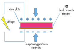
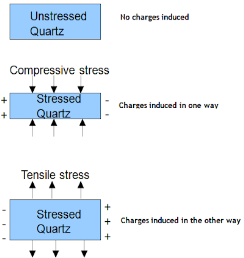
Figure 2: Direct Piezoelectric Effect
The above figure shows the direct piezoelectric effect
Inverse Piezoelectric Effect
We can reverse the same effect. Inverse piezoelectric effect – when an electric field is applied to a crystal it aligns all dipoles present in the material in order. This realignment results in deformation of crystal i.e. converting electrical energy into kinetic or mechanical energy. The reversal of the piezoelectric effect is called the inverse piezoelectric effect.
Using the inverse piezoelectric effect we can develop devices that produce acoustic sound waves. Even medical ultrasound and sonar transducers use the inverse piezoelectric effect.
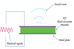
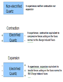
Figure 3: The Inverse Piezoelectric Effect
The above figure shows the inverse piezoelectric effect
Examples of Piezoelectric Materials
All piezoelectric materials are non-conductive for the piezoelectric effect to occur and work. Quartz is natural and first Piezoelectric Material whereas Lead Zirconate Titanate, Barium Titanate, and Lithium Niobate are man-made Piezoelectric Materials.
Piezoelectric Generator or Oscillator
Principle:
This is based on the inverse piezoelectric effect. When a quartz crystal is placed under the effect of an alternating potential difference, vibrations are produced in the crystal. If the frequency of electric oscillations coincides with the natural frequency of vibrations of the crystal, the vibrations will be of large amplitude. When the frequency of the electric field matches the ultrasonic frequency range, then the crystal produces ultrasonic waves.
Electric circuit:
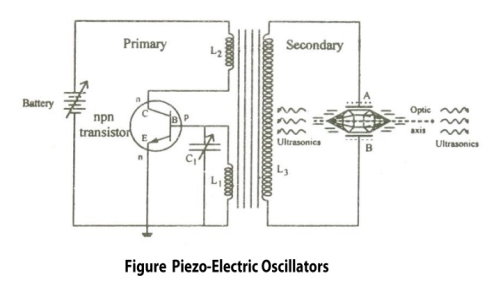
Figure 4:Piezoelectric Generator or Oscillator
Construction:
- It is a common base NPN oscillator circuit.
- Coils L1 and L2 are the primary coils of the transformer.
- Coil L2 is connected to the collector and L1 connected to the base.
- The coil L1 and variable capacitor C1 form the tank circuit of the oscillator.
- Quartz crystal is placed between the metal plates A and B to form a parallel plate capacitor.
- Quartz Crystal is connected to the secondary coil L3 of the transformer through which output or ultrasonic wave is obtained.
- The frequency of the oscillations can be changed by changing the value of capacitance.
Working:
As soon as the circuit is closed, the current starts to flow through the circuit and charges the capacitor. After the charging is completed the capacitor starts discharging through the inductor L1, this energy is stored in the form of the electric field in capacitor C1 and the form of the magnetic field in inductor L1.
Due to this high frequency, electric oscillations are produced in the tank circuit. The transistor is also produced by electric oscillations. This energy or oscillations is provided to the secondary coil which is again fed to the quartz crystal. Thus the oscillating electric field is converted to mechanical vibration of the crystal.
When the frequency of electric oscillations is equal to that of the natural frequency of the crystal, resonance is achieved and the sound waves of maximum amplitude are produced. Thus by using the inverse piezoelectric effect high-frequency ultrasonic waves are produced.
Condition for Resonance:
Frequency of the oscillator circuit = Frequency of the vibrating crystal

Where,
L1 is the inductance of the circuit
C1 is the capacitance of the circuit
t = Thickness of crystal slab
Y = Young's Modulus of material
ρ = Density of material
k = 1, 2, 3. .. (Integer Multiple)
Advantages:
- High-frequency ultrasonic waves can be produced.
- This method is more effective than Magnetostriction oscillator.
- The output power is very high
- We can get a stable and constant frequency of ultrasonic waves.
- It is not affected by temperature humidity
Disadvantages:
- Quartz crystal is very costly.
- Cutting and shaping the crystal is difficult.
Key Takeaways
- Ultrasonic waves are produced by a Piezo-electric generator or oscillator
- The piezoelectric effect transforms kinetic or mechanical energy into electrical energy, due to crystal deformation. When the material is compressed or squeezed, this Mechanical stress applied to the material generates electricity.
- Piezoelectric Generator or Oscillator is based on the principle of inverse piezoelectric effect.
- Inverse piezoelectric effect when an electric field is applied to a crystal it aligns all dipoles present in the material in order. This realignment results in deformation of crystal i.e. converting electrical energy into kinetic or mechanical energy. The reversal of the piezoelectric effect is called the inverse piezoelectric effect.
- Condition for Resonance for Piezoelectric Generator is given as

MAGNETOSTRICTION EFFECT
Production of Ultrasonic Wave
Ultrasonic waves are produced by the following method Magneto-striction generator or oscillator
Magneto-striction generator or oscillator
Principle: Magnetostriction effect: Magnetostriction is a property of magnetic materials like nickel or iron that causes them to change their shape or dimensions during the process of magnetization. i.e. when this material is placed in the magnetic field parallel to its length it changes its dimensions. This is called the Magnetostriction effect.
Figure
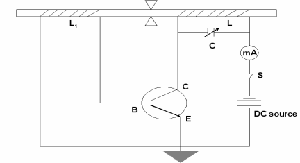
Figure 5:Magneto-striction generator or oscillator
Construction
- In the above figure, we are using NPN Transistor
- In which battery is connected in such a way that emitter is forward biased and collector is reverse biased.
- Current can be produced by applying necessary biasing to the transistor with the help of the battery.
- The current produced in a circuit can be noted by the mill ammeter connected across the coil L.
- The ends of the ferromagnetic rod A and B are wound by the coils L1 and L.
- The coil L1 is connected to the base of the NPN transistor The coil L is connected to the collector of the NPN transistor as shown in the figure.
- The frequency of the oscillatory circuit (LC) can be adjusted by the condenser C.
Working
The rod is initially magnetized by the DC power supply. The transistor is properly biased. The battery is switched on and hence current is produced by the transistor. This current is passed through coil L, this current causes a change in the magnetization of the rod. Now, the rod starts vibrating due to the Magnetostriction effect.
When the rod is vibrating and the coil is wounded over a vibrating rod, An emf is induced in coil L, this induces an emf to coil L1 & a part of it is feed as input to the base. Hence, this feedback system makes the transistor operates continuously. The e.m.f. Induced in the coil called a converse Magnetostriction effect. In this way, the current is maintained in the transistor so as the vibrations.
The frequency of the oscillatory circuit is adjusted by the condenser C and when this frequency is equal to the frequency of the vibrating rod, resonance occurs. At resonance, the rod vibrates longitudinally with larger amplitude producing ultrasonic waves of high frequency along both ends of the rod.
Condition for resonance
Frequency of the oscillatory circuit = Frequency of the vibrating rod

Where,
L is the inductance of the circuit
C is the capacitance of the circuit
l is the length of the rod.
E is the young’s modulus of the material of the rod.
ρ is the density of the material of the rod.
Advantages
- This Oscillatory circuit is simple to construct.
- Magnetostrictive materials are easily available at a low cost
- Large output power can be generated by using this method.
Disadvantages
- It can produce frequencies up to 3 MHz only.
- As rod depends on temperature and the degree of magnetization so it becomes difficult to get a constant single frequency.
- As the frequency is inversely proportional to the length of the vibrating rod, so if you increase the frequency, the length of the rod gets decreased which is practically impossible.
Key Takeaways
- Ultrasonic waves are produced by Magneto-striction generator or oscillator
- Magneto-striction generator or oscillator based on the principle of Magnetostriction effect.
- Magnetostriction is a property of magnetic materials like nickel or iron that causes them to change their shape or dimensions during the process of magnetization. i.e. when this material is placed in the magnetic field parallel to its length it changes its dimensions. This is called the Magnetostriction effect.
- Condition for resonance for Magneto-striction generator is given by

3.2.3 PROPERTIES OF ULTRASONIC WAVES
- The ultrasonic waves cannot travel through a vacuum.
- These waves travel with speed same as sound waves travel in any given medium.
- In a homogeneous medium, the velocity of the ultrasonic wave is constant.
- These waves can also weld some material like plastics and metals.
- They have high energy content.
- Ultrasonic waves get reflected, refracted, and absorbed just like sound waves.
- They can be transmitted over large distances without any appreciable loss of energy.
- They produce an intense heating effect when passed through a substance.
- The ultrasonic waves have a high frequency.
- Because of their smaller wavelength, Ultrasonic waves produce negligible diffraction effects.
- Ultrasonic waves can produce vibrations in low viscosity liquids.
- When the ultrasonic wave is absorbed by a medium, it produces heat because of high frequency and high energy, and that energy is used to drill and cut thin metals.
3.2.4 DETECTION METHODS OF ULTRASONIC WAVES
Ultrasonic waves propagated through a medium can be detected in a number of ways. Some of the methods employed are as follows:
(1) KUNDT’S TUBE METHOD
Kundt devised an experimental technique in 1889 to study the transmission of sound in different materials.
Kundt’s tube consists of a horizontal glass tube about 1 m long and 5 cm in diameter. One end of the tube has an adjustable piston and the other end has a loosely fitted cardboard cap that is firmly fixed to a metal rod. The metal rod is clamped in the middle at B on a horizontal table to ensure minimum disturbance during the use of Kundt’s tube. A small amount of lycopodium powder is scattered in the tube. When ultrasonic waves are incident on the tube and pass through it, the lycopodium powder collects in the form of heaps at the nodal points and is blown off at the antinodal points. The distance between subsequent nodes is then equal to half the magnitude of the wavelength of ultrasonic waves. This information can then be used to determine the frequency of the waves.

Figure 6: Kundt’s tube
This method cannot be used if the wavelength of ultrasonic waves is very small i.e., less than few mm. In the case of a liquid medium, instead of lycopodium powder, powdered coke is used to detect the position of nodes.
(2) SENSITIVE FLAM METHOD
The formation of nodes and antinodes in the presence of ultrasonic waves can be exploited in another interesting way to detect and determine the frequency of the waves A narrow sensitive flame is moved along the medium. At the positions of antinodes, the flame is steady. At the positions of nodes, the flame flickers because there is a change in pressure. In this way, positions of nodes and antinodes can be found out in the medium. The average distance between the two adjacent nodes is equal to half the wavelength. If the value of the frequency of ultrasonic wave is known, the velocity of ultrasonic wave propagated through the medium can be calculated.
(3) THERMAL DETECTORS
This is the most commonly used method of detection of ultrasonic waves. Whenever an ultrasonic wave propagates through a medium, it causes alternate compressions and rarefactions in the medium. Due to these compressions and rarefactions the temperature of the medium change at the nodes while remaining almost constant at antinodes. A thermal detector comprises of a fine platinum wire whose resistance changes at the nodes due to these temperature variations. The complete thermal detector uses the fine platinum wire as one of the arms of a sensitive bridge arrangement. Using this bridge arrangement, changes in the resistance of the platinum wire at the nodes can be measured as a function of time. These measurements can then be used to determine the frequency of ultrasonic waves. As the detector element is moved through the medium, the bridge remains balanced at antinodes but gets off-balance at nodes.
(4) QUARTZ CRYSTAL METHOD OR PIEZOELECTRIC DETECTOR
This method is based on the principle of Piezo-electric effect. Piezoelectric crystals have the ability to develop an electric potential when a stress is applied across certain faces of the crystal. This phenomenon can be used to detect ultrasonic waves. One pair of faces of a quartz crystal (piezoelectric material) is subjected to ultrasonic waves. An alternating potential then develops across the perpendicular faces. This potential can be amplified and measured to detect the presence of ultrasonic waves.
When one pair of the opposite faces of a quartz crystal is exposed to the ultrasonic waves, the other pairs of opposite faces developed opposite charges. These charges are amplified and detected using an electronic circuit.
Key Takeaways
- Ultrasonic waves propagated through a medium can be detected in a number of ways.
- Kundt’s Tube Method cannot be used if the wavelength of ultrasonic waves is very small i.e., less than few mm.
- Sensitive Flam Method : If the value of the frequency of ultrasonic wave is known, the velocity of ultrasonic wave propagated through the medium can be calculated.
- Thermal Detectors can be used to determine the frequency of ultrasonic waves Quartz Crystal Method Or Piezoelectric Detector method is based on the principle of Piezo-electric effect.
3.2.5 APPLICATIONS OF ULTRASONIC WAVES
Used in Medical applications
- Ultrasonic waves are used to treat patients having a stone in the kidney. This high frequency and lower wavelength wave used to break kidney stones into tiny pieces that can be easily flushed out through urine.
- Ultrasonic waves are used in echocardiography.it is used to capture the images of the heart and its features and detect the problems associated with the heart.
- Ultrasonic waves are used in Ultrasound scans/Ultrasonography. It is very commonly used to capture images of internal body organs such as the liver, kidney, and uterus. It helps to diagnose and helps in treating the problems of the patient. In this method, ultrasound waves are made to travel through the body to the organ. They get reflected from the organ which is to be diagnosed and then these waves converted to electrical signals which can be monitored on a screen.
- Ultrasonography is used to observe the growth of the fetus inside the uterus.
- Ultrasonic waves are used to treat patients having a stone in the kidney. These high-frequency waves are used to break kidney stones into tiny pieces that can be easily flushed out through urine.
Used in Industrial Applications
- Ultrasound is used to clean internal parts of the machine Because of the high frequency of the waves, the dust particles just fall out.
- It is used to detect defects, flaws, cracks in machine parts, bridges, buildings, etc. the presence. The ultrasound waves are reflected from the cracks indicating a defect.
Used in SONAR (Sound Navigation and Ranging)
- SONAR is a device that uses ultrasonic waves to measure distances that are practically impossible to measure - the depth of the ocean, distance, and direction of underwater objects.
- SONAR comprises an ultrasound transmitter and detector fitted in a ship. The transmitter transmits ultrasonic waves which travels to the bottom of the ocean and comes back and detected.
Used in Food Processing
- In recent years, Ultrasonic waves are also used in food processing
Example: A cinema hall has a volume of 7500m3. It is required to have a reverberation time of 1.5 sec? What should be the absorption in the hall?
Solution:
Given
Volume = 7500m3
Reverberation time T = 1.5 sec
We know that reverberation time is given by
T = 0.165 V/
T = 0.165 V/ A
Where V-Volume of the hall in m3
A - Absorption coefficient
1.5 = 0.165 x 7500/A
A= 825 O.W.S
Example: A volume of the room is 1200m3. The wall area of the room is 200 m3. The floor wall area of the room is 120m3 and the ceiling area is 120m3 and. The average sound absorption coefficient (i) for walls is 0.03 (ii) for the ceiling is 0.80 (iii) for the floor is 0.06. Calculate the average absorption coefficient and reverberation time?
Solution:
Given
Volume = 1200m3
The average absorption coefficient is
A = a1s1 +a2s2 +a3s3 / s1 +s2 +s3
A = (0.03 x 200 + 0.80 x120 +0.06 x 120) / (200+120+120)
A = 0.2389 =0.24 (approx.)
Now the total absorption of room = As =0.24 x460 =110.40 O.W.S.
Reverberation Time T = 0.165 V/AS = 0.165 x 1200/ 109.2
= 1.80 seconds
Example: For an empty hall of size 20x15x10 m3 the reverberation time is 3.5 sec. Calculate the average absorption coefficient. What area of the wall should be covered by the curtain to reduce reverberation time by 2.5 seSSc. Given the absorption coefficient of curtain clothe is 0.5
Solution:
A =as = (0.165) x (20x15x10)/ 3.5 = 138 m2
When the wall is covered with the curtain clothe
2.5 = (0.165) x (20x15x10)/ 0.5x s
Therefore area of the wall covered by the curtain
s = 483- (2.5 x 138) /2.5 x 0.5
110.4 m2
Reference
1. Engineering physics- Hitendra K Malik, A.K.Singh, Tata McGraw Hill Education Private Limited, New Delhi
2. Engineering Physics, R.K. Gaur and S.L. Gupta, Dhanapat Rai Publications
3. A Text Book of Engineering Physics, M.N. Avadhanulu, P.G. Kshirsagar, S. Chand and Company Ltd.
4. Solid State Physics, S.O. Pillai, McGraw Hill Publications