UNIT 4
Engineering Mechanics
a) Graphical and Analytical Treatment of Concurrent and non-concurrent Co- planner forces
There are many ways in which forces can be manipulated. It is often easier to work with a large, complicated system of forces by reducing it to an ever decreasing number of smaller problems. This is called the "resolution" of forces or force systems. This is one way to simplify what may otherwise seem to be an impossible system of forces acting on a body. Certain systems of forces are easier to resolve than others. Coplanar force systems have all the forces acting in in one plane. They may be concurrent, parallel, non-concurrent or non-parallel. All of these systems can be resolved by using graphic statics or algebra.
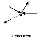
A concurrent coplanar force system is a system of two or more forces whose lines of action ALL intersect at a common point. However, all of the individual vectors might not acutally be in contact with the common point. These are the most simple force systems to resolve with any one of many graphical or algebraic options.
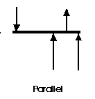
A parallel coplanar force system consists of two or more forces whose lines of action are ALL parallel. This is commonly the situation when simple beams are analysed under gravity loads. These can be solved graphically, but are combined most easily using algebraic methods.
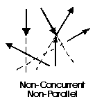
The last illustration is of a non-concurrent and non-parallel system. This consists of a number of vectors that do not meet at a single point and none of them are parallel. These systems are essentially a jumble of forces and take considerable care to resolve.
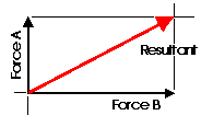
Almost any system of known forces can be resolved into a single force called a resultant force or simply a Resultant. The resultant is a representative force which has the same effect on the body as the group of forces it replaces. (A couple is an exception to this) It, as one single force, can represent any number of forces and is very useful when resolving multiple groups of forces. One can progressively resolve pairs or small groups of forces into resultants. Then another resultant of the resultants can be found and so on until all of the forces have been combined into one force. This is one way to save time with the tedious "bookkeeping" involved with a large number of individual forces. Resultants can be determined both graphically and algebraically It is important to note that for any given system of forces, there is only one resultant.

It is often convenient to decompose a single force into two distinct forces. These forces, when acting together, have the same external effect on a body as the original force. They are known as components. Finding the components of a force can be viewed as the converse of finding a resultant. There are an infinate number of components to any single force. And, the correct choice of the pair to represent a force depends upon the most convenient geometry. For simplicity, the most convenient is often the coordinate axis of a structure.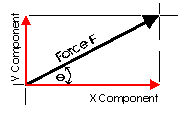
This diagram illustrates a pair of components that correspond with the X and Y axis. These are known as the rectangular components of a force. Rectangular components can be thought of as the two sides of a right angle which are at ninety degrees to each other. The resultant of these components is the hypotenuse of the triangle. The rectangular components for any force can be found with trigonometrically relationships: Fx = F cos theta, Fy = F sin theta (where theta is the angle). There are a few geometric relationships that seem common in general building practice in North America. These relationships relate to roof pitches, stair pitches, and common slopes or relationships between truss members. Some of these are triangles with sides of ratios of 3-4-5, 1-2-sqrt3, 1-1-sqrt2, 5-12-13 or 8-15-17. Commiting the first three to memory will simplify the determination of vector magnitudes when resolving more difficult problems.
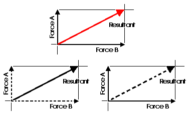
When forces are being represented as vectors, it is important to should show a clear distinction between a resultant and its components. The resultant could be shown with color or as a dashed line and the components as solid lines, or vice versa. NEVER represent the resultant in the same graphic way as its components.
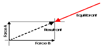
Any concurrent set of forces, not in equilibrium, can be put into a state of equilibrium by a single force. This force is called the Equilibrant. It is equal in magnitude, opposite in sense and co-linear with the resultant. When this force is added to the force system, the sum of all of the forces is equal to zero. A non-concurrent or a parallel force system can actually be in equilibrium with respect to all of the forces, but not be in equilibrium with respect to moments.
Graphic Statics and graphical methods of force resolution were developed before the turn of the century by Karl Culmann. They were the only methods of structural analysis for many years. These methods can help to develop an intuitive understanding of the action of the forces. Today, the Algebraic Method is considered to be more applicable to structural design. Despite this, graphical methods are a very easy way to get a quick answer for a structural design problem and can aid in the determination of structural form.
Graphic Methods of Coplanar Force Resolution
The Parallelogram of Forces Method is one of the graphical methods developed to find the resultant of a coplanar force system. Two or more concurrent forces can be replaced by a single resultant force that is statically equivalent to these forces.

The illustration shows two vectors and their resultant. The resultant force is shown as the dashed vector. In order to resolve these forces graphically, one must first extend the lines of action of two concurrent forces until they intersect. This intersection is known as the point of origin for the system. Both forces, as well as the resultant, must ALL act either away from or toward the point of origin.
The resultant can be represented graphically by the diagonal of the parallelogram formed by using the two force vectors to determine the length of the sides of the parallelogram. The magnitude of the resultant can be accurately measured as the scaled length of the diagonal. The resultant MUST go through the point of intersection of its components!!!
(Remember: graphical solutions depend upon the accuracy of the drawing. The length of each vector should be carefully scaled to equal the magnitude 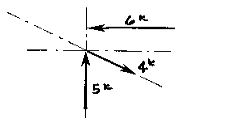 of the force).
More than two non-parallel forces can be combined by successively eliminating one of the forces. Combine any two of the forces into their resultant by the parallelogram method. Combine this resultant with any of the remaining forces (or with the resultant of any of the remaining forces) until all of the forces are included. One must remember that the vectors can only be translated (or moved) along their lines of action. Two vectors (or Forces) cannot be combined (or resolved) until both of them are meeting head-to-head or tail-to-tail!
The resolution of this system is a single vector that has a magnitude of approximately 4k with a direction of up and to the left.
The Triangle of Forces Method is another graphical method developed to find the resultant of a coplanar force system. Since the opposite sides of a parallelogram are equal, a force triangle may also be found instead of using the parallelogram method. This method is quite useful because it can be successively applied to any number of concurrent forces.

To calculate the resultant of the force system shown above, move force A so that it's tail meets the head of force B. Now forces A and B form a "Head-to-Tail" arrangement. The resultant R is found by starting at the tail of B (the point of intersection of forces A and B) and drawing a vector which terminates at the head of the transposed A. Note that if force B had been transposed instead of force A, the resultant would have started from the tail of A and terminated at the head of force B. Again, this process could be repeated for any number of force vectors.
The resultant is described by the vector's magnitude and direction. These are determined by scaling the length and angle respectively. The accuracy of these values depends upon the accuracy of the graphics.
b) Free Diagram
A free-body diagram is a sketch of an object of interest with all the surrounding objects stripped away and all of the forces acting on the body shown. The drawing of a free-body diagram is an important step in the solving of mechanics problems since it helps to visualize all the forces acting on a single object. The net external force acting on the object must be obtained in order to apply Newton's Second Law to the motion of the object.
A free-body diagram or isolated-body diagram is useful in problems involving equilibrium of forces. Free-body diagrams are useful for setting up standard mechanics problems.
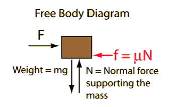
Process to Draw a Free-Body Diagram
To construct a free body diagram, the following three steps are necessary.
- Draw Outlined Shape.
Imagine that the particle is to be isolated from its environments by drawing its outlined shape.
b. Show All the forces.
Then on this sketch, show all the types of forces. Identify Each Force that are known and unknown and display them.
c. Identify each force
Known forces are displayed with magnitude and direction. Letters are used to represent the magnitudes and directions of forces that are unknown.
For understanding the free-body diagram, we will consider the following example:
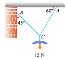
Suppose, in this example there are two strings (AC and BC) attached to an object at point C. Thus, the first step involves drawing a simple diagram representing the outline of all components.
Then, we need to show all the forces that are contributing in the given diagram. Here, there is 15 N force acting at point C, and there is tension in strings BC and AC due to 15 N force acting at C. Thus, identifying and displaying these forces onto the outline diagram is the second step.
The third step is finding the magnitude and direction of the forces and displaying them on the outline diagram. Using these steps, we can draw the free-body diagram as shown below.
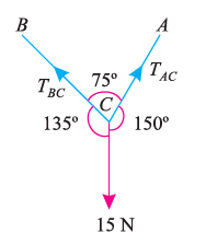
If a body is shown with all external forces acting on it so that the body is in equilibrium, such diagram is called as free body diagram.
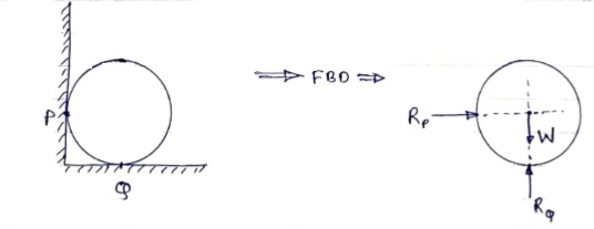
To draw the free body diagram, we have to remove all the restrictions like wall, floor, hinge, any other support and replace them by reactions which these support extents on the body.
Ex – 1) Draw FBD of a bar supported and loaded as shown below.

2) Draw FBD of sphere supported as shown below.
A free-body diagram is a sketch of an object of interest with all the surrounding objects stripped away and all of the forces acting on the body shown. The drawing of a free-body diagram is an important step in the solving of mechanics problems since it helps to visualize all the forces acting on a single object. The net external force acting on the object must be obtained in order to apply Newton's Second Law to the motion of the object.
A free-body diagram or isolated-body diagram is useful in problems involving equilibrium of forces.
Free-body diagrams are useful for setting up standard mechanics problems.

c) Force Diagram and Bow’s notations,
Bow's Notation is a labelling convention whereby the spaces in between any group of forces is labelled with a capital letter such that each force is then straddled by two letters. Since, within a Framed Structure all forces are assumed to be carried within the frame Members, it follows that all spaces within a frame are also labelled such that each Member is also straddled by two letters as shown.
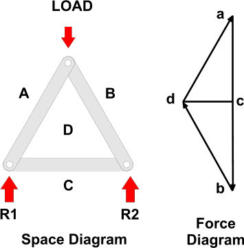
Labelling is carried out clockwise around the frame and each joint is then considered in turn, starting with the joint where there is sufficient data to draw a Force Diagram.
In the example shown:
- We can assume the Load is known and, working clockwise around the joint at the apex, the Vector can be drawn, scaled to its magnitude, and labelled with a direction arrow as creating a force a down to b - since we know the load acts downwards (note the convention to use lower case letters on Force Diagrams).
- The Lines of Action of the force within Members BD and DA are given by the frame drawing (or Space Diagram) and can be drawn through b and a respectively to intersect in d.
- It is a feature of Force Diagrams that the lines of force will follow each other around a Force Polygon and so, given the downwards direction of ab, it can be seen that, around the apex, the forces within both BD and DA are pointing upwards.
- Since all Members must stay still, or be in Equilibrium there must be equal and opposite forces at the lower ends of BD and DA (i.e. AD and DB) indicating that the these Members are Struts - which is what we would expect.
- This additional information can be used to determine other forces (e.g. The Reactions) by working clockwise around the two lower joints and adding dc for example, to the Force Diagram.
A very basic concept when dealing with forces is the idea of equilibrium or balance. In general, an object can be acted on by several forces at the same time. A force is a vector quantity which means that it has both a magnitude (size) and a direction associated with it. If the size and direction of the forces acting on an object are exactly balanced, then there is no net force acting on the object and the object is said to be in equilibrium. Because there is no net force acting on an object in equilibrium, then from Newton's first law of motion, an object at rest will stay at rest, and an object in motion will stay in motion.
Let us start with the simplest example of two forces acting on an object. Then we will show examples of three forces acting on a glider, and four forces acting on a powered aircraft.
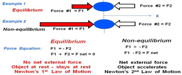
In Example 1 on the slide, we show a blue ball that is being pushed by two forces, labelled Force #1 F1 and Force #2 F2. Remember that forces are vector quantities and direction is important. Two forces with the same magnitude but different directions are not equal forces. In fact,
F1 = - F2
For the coordinate system shown with the letter X below the ball. If we sum up the forces acting on the ball, we obtain the force equation on the left:
F1 + F2 = F net = 0
Where F net is the net force acting on the ball. Because the net force is equal to zero, the forces in Example 1 are acting in equilibrium.
There is no net force acting on the ball in Example 1. Since the ball is initially at rest (velocity equals zero), the ball will remain at rest according to Newton's first law of motion. If the ball was travelling with a uniform velocity, it would continue travelling at the same velocity.
In Example 2, we have increased the magnitude of Force #1 so that it is much greater than Force #2. The forces are no longer in equilibrium. The force equation remains the same, but the net force is not equal to zero. The magnitude of the net force is given by:
F1 > - F2
F1 + F2 = F net
|F net| = |F1| - |F2|
Where the "| |" symbols indicate the magnitude of the quantity included between the ends. The direction of the net force would be in the positive X direction because F1 is greater then F2. According to Newton's second law of motion, the ball would begin to accelerate to the right. Because there is a net force in Example 2, the forces are not in equilibrium.
Truss:
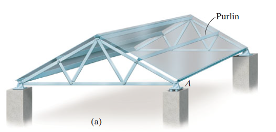
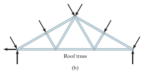
A truss is a structure which is made of slender members those are joined together at the end points. Planar trusses lie in one single plane and these are frequently used to support some of the bridges and roofs. Fig. (a) is a typical roof-supporting truss used for construction. Since this loading turns in the similar plane as the truss, Fig. (b), the analysis of the forces developed in the truss members will be two-dimensional.
Simple truss problems can be solved using two methods:
a Method of joints
b Method of sections
a) Method of joints
If a truss is in equilibrium, then each of its joints must also be in equilibrium. Procedure - starts with a joint that has no more than two unknown forces
- Establish the x and y axis; - At this joint, ∑ Fx = 0 and ∑ Fy = 0;
- After finding the unknown forces applied on this joint, these forces become the given values in the analysis of the next joints.
The joints with external supports always connect with two truss members. Thus many times, the analysis starts from analysing the supports. Therefore very often the analysis begins with finding the reaction forces applied at the supports.
- Pay attention to symmetric systems and zero force members. Identification of these special cases sometimes will make the whole analysis way easier
For solving simple truss example using method of joints we will follow the below procedure.
Draw the free body diagram which minimum one known and 2 unknown force.
Use one of the two methods described above for establishing the sense of an unknown force.
Draw x and y axed such that we can easily solve for x and y components and then apply the two force equilibrium equations and Solve for the two unknown member forces and verify their correct sense.
b Method of sections
If a truss is in equilibrium, then whichever section of the truss being considered must also be in equilibrium.
Finding the reaction forces: Make a cut through the members where the unknown forces are applied; - Establish equilibriums for one of the sections:
∑ Fx = 0; ∑ Fy = 0; ∑M = 0;
If your result comes out to be negative, then it means you assumed a wrong direction of the force.
Application - The method of sections is commonly used when the forces in only a few particular members of a truss are to be determined;
The method of sections is always used together with the method of joints to analyse trusses.
For solving simple truss example using method of sections we will follow the below procedure.
Make a cut in section where forces are to be determined.
Initially determine support reactions.
Draw the free-body diagram of that segment of this type of truss which is sectioned with minimum forces.
Unknown member forces can be found by above mentioned methods.
Moments should be summed about a point that lies at the intersection of the lines of action of two unknown forces, so that the third unknown force can be determined directly from the moment equation.
If two of the unknown forces are parallel, forces may be summed perpendicular to the direction of these unknowns to determine directly the third unknown force.
Plane Frame:
Frames are the type of structures which are often composed of pin-connected multi force members, i.e., members that are subjected to more than two forces. Frames are used to support loads.
The process for solving problems of plane frames is as discussed below.
Draw the free-body diagram of the entire frame or machine, a portion of it, or each of its members. The choice should be made so that it leads to the most direct solution of the problem.
When the free-body diagram of a group of members of a frame or machine is drawn, the forces between the connected parts of this group are internal forces and are not shown on the free-body diagram of the group.
Forces common to two members which are in contact act with equal magnitude but opposite sense on the respective free-body diagrams of the members.
Two-force members, regardless of their shape, have equal but opposite collinear forces acting at the ends of the member.
In many cases it is possible to tell by inspection the proper sense of the unknown forces acting on a member; however, if this seems difficult, the sense can be assumed.
Remember that a couple moment is a free vector and can act at any point on the free-body diagram. Also, a force is a sliding vector and can act at any point along its line of action.
Count the number of unknowns and compare it to the total number of equilibrium equations that are available. In two dimensions, there are three equilibrium equations that can be written for each member.
Sum moments about a point that lies at the intersection of the lines of action of as many of the unknown forces as possible.
If the solution of a force or couple moment magnitude is found to be negative, it means the sense of the force is the reverse of that shown on the free-body diagram.