UNIT 5
ENGINEERING MECHANICS
Centre of Gravity and moment of Inertia
Centroid
In Geometry, the centroid is an important concept related to a triangle. A triangle is a three-sided bounded figure with three interior angles. Based on the sides and angles, a triangle can be classified into different types such as
- Scalene triangle
- Isosceles triangle
- Equilateral triangle
- Acute-angled triangle
- Obtuse-angled triangle
- Right-angled triangle
Centroid Definition
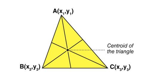
The centroid is the centre point of the object. The point in which the three medians of the triangle intersect is known as the centroid of a triangle. It is also defined as the point of intersection of all the three medians. The median is a line that joins the midpoint of a side and the opposite vertex of the triangle. The centroid of the triangle separates the median in the ratio of 2: 1. It can be found by taking the average of x- coordinate points and y-coordinate points of all the vertices of the triangle.
Centroid Theorem
The centroid theorem states that the centroid of the triangle is at 2/3 of the distance from the vertex to the mid-point of the sides.
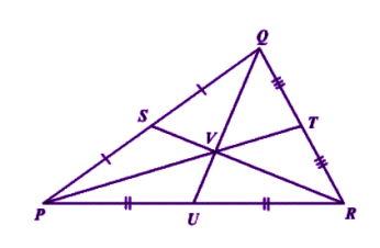
Suppose PQR is a triangle having a centroid V. S, T and U are the midpoints of the sides of the triangle PQ, QR and PR, respectively. Hence as per the theorem;
QV = 2/3 QU,
PV = 2/3 PT and RV = 2/3 RS
Centroid of a Right Angle Triangle
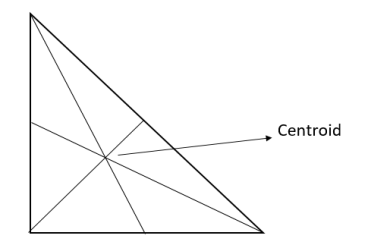
The centroid of a right angle triangle is the point of intersection of three medians, drawn from the vertices of the triangle to the midpoint of the opposite sides.
Centroid of a Square
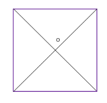
The point where the diagonals of the square intersect each other is the centroid of the square. As we all know, the square has all its sides equal. Hence it is easy to locate the centroid in it. See the below figure, where O is the centroid of the square.
Properties of centroid
The properties of the centroid are as follows:
- The centroid is the centre of the object.
- It is the centre of gravity.
- It should always lie inside the object.
- It is the point of concurrency of the medians.
Centroid Formula
Let’s consider a triangle. If the three vertices of the triangle are A(x1, y1), B(x2, y2), C(x3, y3), then the centroid of a triangle can be calculated by taking the average of X and Y coordinate points of all three vertices. Therefore, the centroid of a triangle can be written as:
Centroid of a triangle = ((x1+x2+x3)/3, (y1+y2+y3)/3)
Centroid Formula for Different Shapes
Here, the list of centroid formula is given for different geometrical shapes.
Shapes | Figure | x̄ | ȳ | Area |
Triangular area | 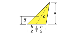 | – | h/3 | Bh/2 |
Quarter-circular area | 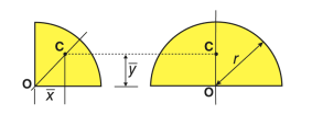 | 4r/3π | 4r/3π | πr2/4 |
Semi-circular area | 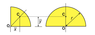 | 0 | 4r/3π | πr2/2 |
Quarter-elliptical area | 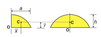 | 4a/3π | 4b/3π | πab/4 |
Semi elliptical area | 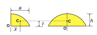 | 0 | 4b/3π | πab/2 |
Semi parabolic area | 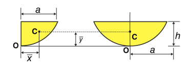 | 3a/8 | 3h/5 | 2ah/3 |
Parabolic area | 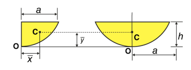 | 0 | 3h/5 | 4ah/3 |
Parabolic spandrel | 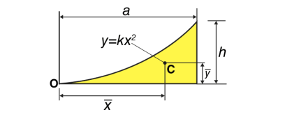 | 3a/4 | 3h/10 | Ah/3 |
Centre of Gravity
One way to look at gravity is to look at it as a force that pulls things downward more precisely towards the centre of the Earth. But it doesn’t always work like that! Sometimes gravity causes things to topple and turn over, especially if they are high up and unbalanced. No one understands this better than tightrope walkers. While tiptoeing on the high wire, they often wobble from side to side to entertain us, yet they hardly ever fall. Instinctively they understand the physics of forces and manage to stay firmly on the rope. If you, like them, understand a simple concept known as the centre of gravity, you consider balancing a child’s play!
Centre of gravity is a theoretical point in the body where the total weight of the body is thought to be concentrated. It is important to know the centre of gravity because it predicts the behaviour of a moving body when acted on by gravity and it is also useful in designing static structures such as buildings and bridges.
In a uniform gravitational field, the centre of gravity is identical to the centre of mass. Yet, the two points do not always coincide. For the Moon, the centre of mass is very close to its geometric centre. However, its centre of gravity is slightly towards the Earth due to the stronger gravitational force on the Moon’s near side.
In a symmetrically shaped object formed of homogenous material, the centre of gravity may match with the geometric centre of the body. However, an asymmetrical object composed of a variety of materials with different masses is likely to have its centre of gravity located at some distance away from its geometric centre. In hollow bodies or irregularly shaped bodies, the centre of gravity lies at a point external to the physical material.
Calculating the Centre of Gravity
In the next few sections, we will learn how to determine the centre of gravity of objects. In general, determining the centre of gravity may be a complicated procedure because the mass and weight may not be uniformly distributed throughout the object.
Determining the Centre of Gravity for Symmetrical Bodies
For simple shaped object, the centre of gravity can be determined by the following ways:
- When we balance an object with the help of a string or an edge, the point at which the object balances is the centre of gravity.
- Another simple physical procedure employed to determine the centre of gravity is as follows:
Suspending the plate given in the figure by attaching a cord to point A and then by attaching the cord at point C, the centre of gravity of the plate can be located.
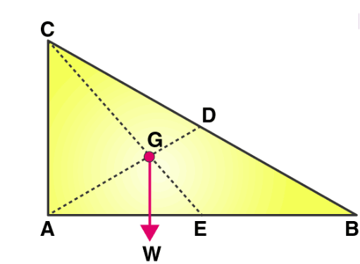
The line AD is vertical when the plate is suspended from A; likewise, the line CE is vertical when suspended from C. The centre of gravity of the plate lies at the intersection of AD and CE. When an object is suspended from any single point, its centre of gravity lies directly beneath that point.
Determining the Centre of Gravity for Asymmetrical Bodies
We make use of calculus to determine the centre of gravity when the mass is not distributed uniformly. We denote the integration of a continuous function with respect to weight using the symbol S dw. Then, the centre of gravity is determined as follows:
Cg × W = S x dW
Here, x is the distance from a reference line, dw is an increment of weight, and W is the total weight of the object.
We know that
W=mg
But, the mass of an object is equal to
m=ρV
Combining both the equations, we get
W=gρV
Solving,
DW=gρdV dW=g∗ρ(x,y,z)∗dxdydz
If we have a functional form of the mass distribution, we can solve the equation for the centre of gravity
Cg∗W=g∗SSSx∗ρ(x,y,z)dxdydz
SSS in the equation indicates a triple integral over dx. dy. And dz.
Moment of Inertia:
Moment of force about any point is the product of magnitude of force and perpendicular distance of line of action of force the point
Mo F  d
d
 O
O
d
F

This is known as first moment of force.
- When this product Mo i.e. (F
 d) is again multiplied with distance ‘d’ then
 2
2
 2 is known as second moment of force or moment of inertia of force.
- When force is replaced by area of figure or mass of the body, then second moment is known as area moment of inertia or mass moment of inertia.
A) Area moment of inertia (I)
The second moment of area about a particular axis is known as area moment of inertia about axis
Unit – mm4, Cm4, m4……
First moment of area = area  distance
= mm2  mm
mm
= mm3
Second moment of area = moment (1st) of area  distance
= area  distance
 distance
= mm3  mm
mm
= mm4
B) Mass Moment of Inertia:
The second moment of mass of the body about a particular axis is known as ‘’mass moment of inertia’’ about that axis
Unit – kg.mm2, kg.m2

= 
= kg m2
m2
If entire mass of body be assumed to be concentrated at a certain point which is located at a distance K from given axis such that
 2
2
 =
= 
Then
Distance K is known as Radius of Gyration
Thus Radius of Gyration is defined as the Distance from the axis of reference where whole mass of the body is assumed to be concentrated
For plane figure having negligible mass, we can consider area for finding radius of gyration
Thus
 of an area (plane figure)
 2
2
 
Where, Kxx, Kyy, Kzz is radius of gyration of any area ir body about X, y, z, axis respectively | Kxx =   Kyy =   Kzz =   |
Moments of Inertia for Areas:
When a distributed loading whose intensity varies linearly acts perpendicular to an area, the computation of the moment of the loading distribution about an axis involves a quantity called the moment of inertia of the area or simply area moment of inertia.
Consider a differential plate, subjected to fluid pressure P that varies linearly with depth, as shown in fig, such that  , where,
  is the specific weight of fluid.
The force acting on a acting on the differential area of the plate is given by

The moment of this this force about the x-axis is

Integrating  over the entire area of the plate yields


The integral part of the moment equation is called area moment of inertia about x-axis 

Similarly, area moment of inertia about y-axis is given as,

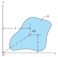
Moment of Inertia for area can also be given as

Where, A is the total area
And k is referred as radius of gyration
Radius of gyration for area of a plate about an axis is defined as the radial distance to a point which would have a same moment of inertia as the plate’s actual distribution of area, if the total area of the plate were concentrated.
It is given by,

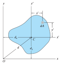
Parallel axis theorem for Area
It states that “the moment of Inertia about an axis is equal to the summation of moment of inertia about the axis passing from centroid of area and the product of total area and square of perpendicular distance between the two axes.”
Mathematically,

Where,  is the moment of inertia about axis passing through the centroid, and d is the perpendicular distance between two axes.
For the system shown below,


Mass moment of Inertia:
The mass moment of inertia of a body is a measure of the body’s resistance to angular acceleration.
Consider a rigid body, rotating about z-axis, as shown in figure.
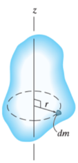
Mass moment of inertia is defined by,

Where, r is the perpendicular distance from the axis of rotation to the arbitrary differential element of the body of mass dm.
The moment of inertia is also written as

Where, m is the total mass of the body
And k is referred as radius of gyration
Radius of gyration for a body rotating about an axis is defined as the radial distance to a point which would have a same moment of inertia as the body’s actual distribution of mass, if the total mass of the plate were concentrated.
In simple words, radius of gyration is the perpendicular distance of the axis of rotation to the point where the entire mass of the body is supposed to be concentrated for dynamic analysis.
It is given by,

Theorem of parallel axes for mass
Theorem of parallel axes states that, “the moment of inertia of the rotating body about an axis is equal to the summation of the moment of inertia of the body about an axis passing through the center of mass and the product of total mass of the body and the square of perpendicular distance between the two axes.”
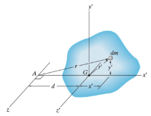
Mathematically,

Where,
 = Moment of inertia about z’ axis passing through the center of mass G
m = total mass of body
d = perpendicular distance between the parallel axes
Theorem of perpendicular axes
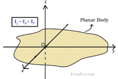
It states that, “for the planar element, the moment of inertia about an axis is equal to the summation of moment of inertias about two mutually perpendicular axes.”
Mathematically,

Types of Support
- Roller Support: -
 Roller support is show in two ways as shown:
 A free body diagram of roller support is shown in figure given below
- Roller support offers only one reaction; which is always perpendicular to the base or plane of roller.
- All the steel trusses of the bridges have one of their ends supported on roller.
- Main advantages of the support are that beam can easily move towards left or right due to expansion & contraction.
2. Hinge support

- In this case, end of the beam is hinged to the support as shown in figure above.
- This type of support offers two reactions, one is parallel to base and perpendicular to the base
- All the steel trusses of the bridges have one of their end roller supported & other end is hinged
- Main advantage of this support is that beam remains stable.
- If both ends of the beam are roller supported, then beam can not be stable. Thus, one support of beam is made roller supported and other is hinged.
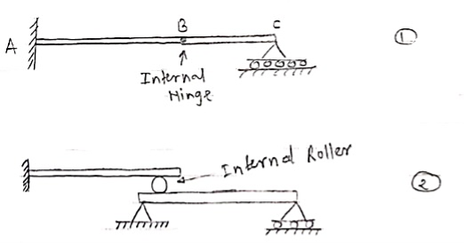
3. Internal Hinge: -
 When two members are connected by the hinge then this type of support is called as internal Hinge.


Internal Hinge
Reactions at internal Hinge
4. Fixed support: -
Fixed support offers three reactions as shown in figure below.
- Reaction in horizontal direction.
- Reaction in vertical direction.
- Moment (fixing moment)

Fixed Support
Type of supports and reaction
- Point load
Load acting at a single point on the beam is known as point load. Its unit is N or kN

2. Uniformly Distributed load (UDL) or Rectangular Load:
A load which is spread over the beam or part of the beam uniformly is known as UDL
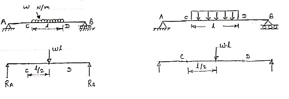
Conversion of UDL or Rectangular load into point load
= Intensity of UDL × distance
= w. l. ------------- N
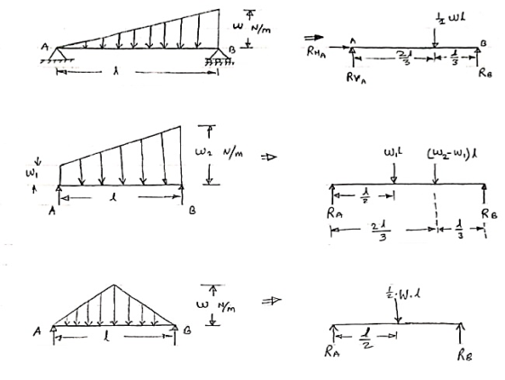
3. Uniformly varying load or Triangular load:
A load whose intensity is linearly varying between the two points on the beam is known as UVL. If an intensity of the load at one end is zero and at other ends is maximum then it is called as uniformly varying load or triangular load.
Following figures shows different types of UVL
- To convert UVL into point load, calculate the area of uniformly varying load.
- For location of point load find x coordinate of centroid of the UVL area.
 .
.

Beam –
It is horizontal structural member on which different types of loads can be supported. It takes load from floor or roof & transfers to column.
The beam may be sometimes constructed in the inclined position for architectural point of view.
Types of Beam: -
- Simply supported beam –
A beam which is just resting on the supports at the end without any connection is known as simply supported beam. It is generally used for vertical landing system.

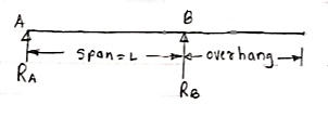
2. Overhanging Beam –
A beam which is supported at the intermediate point other than ends is called as overhanging beam. Here portion of beam is extended beyond the support
 a)
a)
(singly overhanging beam)

b)
(doubly overhanging beam)
3. Cantilever Beam –
A beam which is fixed at one end is called as cantilever beam

Here, there are three reactions components:
- Vertical reaction at A (RVA)
- Horizontal reaction at A (RHA)
- Fixing moment at A (MA)
We can assume any direction for above components.
4. Continuous Beam:
A beam having more than two support is called as continuous beam.

5. Compound Beam:
When two or more beams are joined together by using internal hinge; or when one beam rests over another beam by using internal roller, then such beam is called as compound beam.
