Unit 4
Lasers
In order to have an insight into the principle of laser, we need to understand the way radiation field interacts with matter. In the early 20th century, Planck formulated the theory of spectral distribution of thermal radiation. Einstein, by combining Planck's theory and the Boltzmann statistics gave a theory of stimulated emission which is the governing principle of laser
In thermal equilibrium at temperature T, with radiation frequency n and energy density u(v). Let N1 and N2 be the number of atoms in energy states 1and 2 respectively at any instant. The number of atoms in state 1 absorb a photon and give rise to absorption per unit time
For equilibrium P12 = P21
N1 B12 u(v) = N2 [A21 + B21 u(v)]


According to Boltzmann distribution law number of atoms N1 and N2 in energy states E1 and E2 in thermal equilibrium at temperature T are given by


Substituting N1/N2 in Eq we get
Comparing it with Plank’s Radiation law

We get
(i)  ;
;
B12 = B21, the probability of spontaneous emission is same as that of induced absorption. This means that if these two processes will occur at equal rates, so that no population inversion can be attained in a two-level system.
(ii) 
The ratio of spontaneous emission and stimulated emission is proportional to v3. This implies that the probability of spontaneous emission dominates over induced emission more and more as the energy difference between the two states increases.
Population inversion
Under normal circumstances, the higher an energy level is, the less it is populated by thermal energy. Under some circumstances (for example, the presence of an upper energy level that has a relatively long lifetime), a system can be constructed so that there are more atoms/molecules in an upper energy level than is allowed under conditions of normal thermodynamic equilibrium. Such an arrangement is called a population inversion.
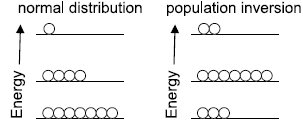
When a population inversion exists, an upper-state system will eventually give off a photon of the proper wavelength and drop to the ground state. This photon, however, can stimulate the production of other photons of exactly the same wavelength because of stimulated emission of radiation. Thus, many photons of the same wavelength (and phase, and other similar characteristics) can be generated in a short time. This is light amplification by stimulated emission of radiation, or LASER—usually seen in lowercase as laser. Lasers typically have a very narrow wavelength range of emission.
Many types of energy levels—electronic, vibrational, bands in semiconductors—are used to make lasers. Many materials are active laser sources, including Cr3+ ions in ruby and alexandrite crystals, Ti3+ in sapphire, Nd3+ in garnet, and a variety of doped semiconductors. Gases or gas mixtures like He/Ne, Ar, Kr, CO2, N2, even Cu(g) can be made to lase. Certain organic dyes can also be made to lase; one advantage is that their laser action has a broader range of wavelengths (20-30 nm) and they can be tuned to a particular wavelength.
Some imp. Points--
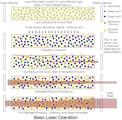
1. Energy is applied to active medium raising active centres to excited energy level.
2. These atoms spontaneously decay to a relatively long-lived, lower energy, metastable state
3. A population inversion is achieved when the majority of atoms have reached this metastable state
4. Lasing action occurs when an electron spontaneously returns to its ground state and produces a photon.
5. If the energy from this photon is of the precise wavelength, it will stimulate the production of another photon of the
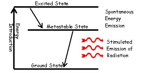
Same wavelength and resulting in a cascading effect.
6. The highly reflective mirror and partially reflective mirror continue the reaction by directing photons back through the medium along the long axis of the laser.
7. The partially reflective mirror allows the transmission of a small amount of coherent radiation that we observe as the “beam”.
8. Laser radiation will continue as long as energy is applied to the lasing medium.
I Gas lasers (He-Ne, CO2)
He-Ne lasers
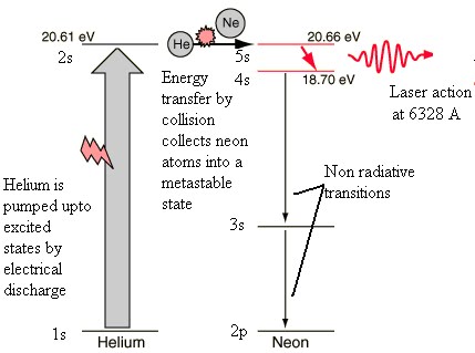
The most common and inexpensive gas laser, the helium-neon laser is usually constructed to operate in the red at 6328 Å. It can also be constructed to produce laser action in the green at 5435 Å and in the infrared at 15,230 Å.
The He – Ne laser has following main parts:

1. The working substance (active medium)- is a long gas discharge tube filled with Helium and Neon gases in ratio 10:1. Ne atoms are active centres where He atoms helps Ne in achieving population inversion.
2. The resonance cavity- the two mirrors arranged externally one is fully reflective and other is partially transmissive forms the optical resonator.
3. Pumping scheme- atoms are excited by electrical discharge. The He atom is pumped to excited state by electrical discharge. One of the excited levels of helium at 20.61 eV is very close to a level in neon at 20.66 eV, so close in fact that upon collision of helium and a neon atom, the energy can be transferred from the helium to the neon atom during collision. Thus, the population inversion is achieved between E4 and E3 of Neon atom.
CO2 Laser
The carbon dioxide gas laser is capable of continuous output powers above 10 kilowatts. It is also capable of extremely high-power pulse operation. It exhibits laser action at several infrared frequencies but none in the visible. It emits laser light at a wavelength of 10.6 mm
1. The working substance (active medium)- is a gas discharge tube of about 1.5 mm2 cross section and 260 mm length filled with mixture of Co2, N2 and Helium gases in ratio 1:5:5. The Co2 molecules are active centres where N2 atoms helps Co2 molecules in achieving population inversion.
2. The resonance cavity- the two mirrors arranged externally one is fully reflective and other is partially transmissive forms the optical resonator.
3. Pumping scheme- atoms are excited by AC or DC electrical discharge.
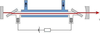
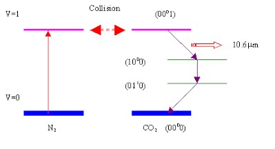
First most of the electrical discharge energy is absorbed by nitrogen gas, only a small part of the energy is absorbed by CO2 molecules directly which raise them from ground state (000) to upper state (001). Large amounts of CO2 molecules collide with the nitrogen molecules and gain the excitation energy. Once excitation is achieved, the CO2 molecules at (001) state will give out energy and jump to lower energy state (100) or (020), thus giving out laser light at frequency 10.6m m or 9.6 m m respectively. The remaining decay from state (100) to (010), (020) to (010) or (010) to ground state (000) will dissipate energy in the form heat instead of light.
II Solid-state lasers (ruby, Neodymium)
Ruby laser:
The ruby laser is the first type of laser actually constructed, first demonstrated in 1960 by T. H. Maiman. The ruby mineral (corundum) is aluminium oxide (Al2O3) with a small amount (about 0.05%) of chromium ions (Cr3+) which gives it its characteristic pink or red color by absorbing green and blue light.
The ruby laser is used as a pulsed laser, producing red light at 6943Å. After receiving a pumping flash from the flash tube, the laser light emerges for as long as the excited atoms persist in the ruby rod, which is typically about a millisecond.
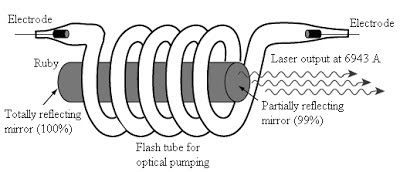
The ruby laser has following main parts:
1. The working substance (active medium)- is in the form of a rod of ruby crystal (10 cm in length, 0.8 cm in diameter) in which Cr3+ are active centres while Al and O2 are inert.
2. The resonance cavity- is made by silvering and polishing the ends of ruby rod. Fully reflecting plates at the left and a partially reflecting plate at the right, both optically plane and accurately parallel.
3. The optical pumping system -consists of a helical xenon discharge tube. It produces flash of few milliseconds.
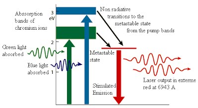
Ruby laser uses a three-level pumping scheme. The xenon discharge generates a flash of white light for few milliseconds. The Cr+3 ions are excited to the E3 level by absorbing green and blue component of white light. From there the Cr+3 ions undergo non-radiative transitions and quickly drop to the metastable level E2. The metastable state has greater life time than E3. Therefore Cr+3 ions accumulate at E2. When more than half ions are accumulated at E2 the population inversion is established between E2 and E1. A chance spontaneous emission leads to chain stimulated emission. Red light (of wavelength 6943 Å) emerges from the front face.
Neodymium-YAG Laser
It is a solid-state laser with four level laser system Neodymium-YAG is used to produce high power. Such lasers have been constructed to produce over a kilowatt of continuous laser power at 10.65 mm (in infra-red region) and can achieve extremely high powers in a pulsed mode.
The Nd: YAG laser has following main parts
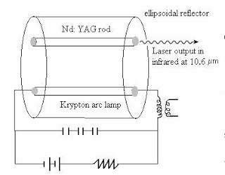
1. The working substance (active medium)- is Yttrium-Aluminium-Garnet (Y3Al5O12), it is transparent and colourless. The neodymium- ion (Nd3+) replaces Y3+ ion in the yttrium-aluminium-garnet (YAG) which makes population inversion possible. Thus Nd3+ are active centres.
2 The resonance cavity- is made by silvering and polishing the ends of laser rod (Nd: YAG rod) to constitute the optical resonator. Fully reflecting plates at the left and a partially reflecting plate at the right, both optically plane and accurately parallel.
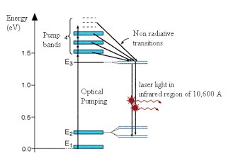
3. The optical pumping system -The pumping if Nd3+ ion is done by krypton arc lamp. The light of wavelength 5000 – 8000 Å excites the ground state Nd3+ ions to the multiple energy levels at E4.
Efficiency of Nd: YAG, laser is high in comparison to ruby laser which is about 2% (while for ruby laser it is only 1%).
It is a four-level system. The Nd3+ ions are excited to the pump bands (Level E4) by the white light (wavelength from 5000Å to 8000Å) of Argon arc lamp. From there they rapidly decay to metastable state E3. Soon the population inversion is established between E3 and E2. A spontaneous decay will start chain of stimulated emissions and laser light of wavelength 10.6 mm is emitted from the front. The Nd3+ ion reaches to the ground level in a non-radiative transition.
I Mono-chromaticity
Highly Monochromatic:
The light from a laser typically comes from one atomic transition with a single precise wavelength. So, the laser light has a single spectral color and is highly monochromatic light available.
II Coherence
Coherence:
The light from a laser is said to be coherent, which means that the wavelengths of the laser light are in phase in space and time. Large number of identical
photons are emitted through stimulated emission and therefore they will be in phase with each other.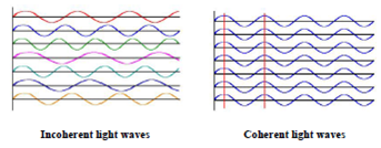
III Directionality and brightness
Highly Directional and Collimated:
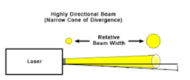
Lasers emit light that is highly directional, narrow beam divergence. The light from laser emerges in an extremely thin beam with very little divergence therefore the beam is also highly collimated. The high degree of collimation arises from the fact that the cavity of the laser has very nearly parallel
front and back mirrors which constrain the final laser beam to a path which is perpendicular to those mirrors. As a result, laser beams are very narrow and do not spread very much. Angle of divergence  ,where D is diameter of beam
IV Laser speckles
Speckle patterns can severely degrade the image quality of laser projection displays, or disturb position measurements with laser pointers. Speckle can often be avoided, e.g. By using a light source with sufficiently large optical bandwidth (short coherence length) such as a super luminescent source. (How much bandwidth is required for that purpose depends on the situation.) For projection displays, one may also work with an optimized screen. However, there are also applications of speckle, e.g. In speckle interferometry.
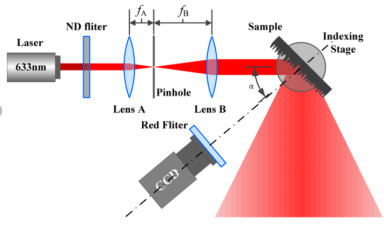
1. Welding and Cutting: The highly collimated beam of a laser can be focused to a microscopic dot of extremely high energy density for welding and cutting. The automobile industry makes extensive use of carbon dioxide lasers with powers up to several kilowatts for computer-controlled welding on auto assembly lines.
2. Communication: The lasers have significant advantages in communication because they are more nearly monochromatic and this allows the pulse shape to be maintained better over long distances when used in optical fibre.
3. Barcode Scanner: Supermarket scanners typically use helium-neon lasers to scan the universal barcodes to identify products. The laser beam bounces off a rotating mirror and scans the code, sending a modulated beam to a light detector and then to a computer which has the product information stored.
4. Laser Printing: The laser printer has in a few years become the dominant mode of printing in offices. The laser is focused and scanned across a photoactive selenium coated drum where it produces a charge pattern which mirrors the material to be printed. This drum then holds the particles of the toner to transfer to paper which is rolled over the drum in the presence of heat.
5. CD’s and Optical Discs: The detection of the binary data stored in the form of pits on the compact disc is done with the use of a semiconductor laser.
6. Surveying and Ranging: Helium-neon and semiconductor lasers have become standard parts of the field surveyor's equipment. A fast laser pulse is sent to a corner reflector at the point to be measured and the time of reflection is measured to get the distance.
7. Laser cooling: The use of lasers to achieve extremely low temperatures has advanced to the point that temperatures of 10-9 K have been reached
8. Laser Spectroscopy: Laser spectroscopy has led to advances in the precision with which spectral line frequencies can be measured, and this has fundamental significance for our understanding of basic atomic processes.
9. Holography: Holography is "lens less photography" in which an image is captured not as an image focused on film, but as an interference pattern at the film.
10. Medicine: Lasers have been used for various medical procedures such as dermatology and cosmetic surgery, wound healings, nerve stimulation, dentistry ophthalmology applications for vision corrections and corneal deceases. And many other therapeutic procedures. Combining the nanoparticles, diode lasers have been also used for cancer therapy, bio-sensing, bio-imaging, drug delivery and diagnostics of cancer cell.
The optical fibre is a cylindrical, long, thin transparent structure made of glass and plastic, which is designed to guide the light wave from one end to another. The light inside the fibre is guided on the principle of Total Internal Reflection (TIR).
Optical fibers are widely used in fibre-optic communications to send information (data).
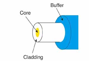
The basic structure of an optical fiber consists of three parts the core, the cladding, and the coating or buffer which are coaxially arranged. The innermost region is called the core, the light in the fibre travels only in the core. The core is surrounded by cladding, which is responsible for keeping the light inside the core. The refractive index of core (n1) is greater than of cladding (n2). The outermost region is called buffer or sheath, which protects the core and cladding from external abrasions
I Acceptance angle and cone
The acceptance angle of an optical fiber is defined based on a purely geometrical consideration (ray optics): it is the maximum angle of a ray (against the fiber axis) hitting the fiber core which allows the incident light to be guided by the core. The sine of that acceptable angle (assuming an incident ray in air or vacuum) is called the numerical aperture, and it is essentially determined by the refractive index contrast between core and cladding of the fiber, assuming that the incident beam comes from air or vacuum:

Here, ncore and ncladding are the refractive indices of core and cladding, respectively, and n0 is the refractive index of the medium around the fiber, which is close to 1 in case of air.
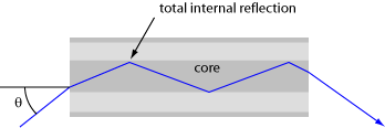
The largest Launch Angle of Incident Light that can propagate down the Fiber optics

II Numerical aperture
Numerical Aperture (NA)
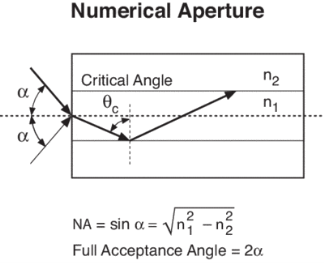
The Numerical Aperture (NA) of a fibre is defined as the sine of the largest angle an incident ray can have for total internal reflectance in the core. Rays launched outside the angle specified by a fibber’s NA will excite radiation modes of the fiber. A higher core index, with respect to the cladding, means larger NA. However, increasing NA causes higher scattering loss from greater concentrations of dopant. A fiber's NA can be determined by measuring the divergence angle of the light cone it emits when all its modes are excited.
Qualitatively, NA is a measure of the light gathering ability of a fiber. It also indicates how easy it is to couple light into a fiber.
III V number
“V Number”
The Normalized Frequency Parameter of a fiber, also called the V number, is a useful specification. Many fiber parameters can be expressed in terms of V, such as: the number of modes at a given wavelength, mode cut off conditions, and propagation constants. For example, the number of guided modes in a step index multimode fiber is given by V2/2, and a step index fiber becomes single-mode for a given wavelength when V<2.405. Mathematically, V=2 π·NA·a/λ where “a” is the fiber core radius.
V – number determines how many modes a fiber can support, it is given by,

Where d is the diameter of the core, l is the wavelength of light used and NA is the numerical aperture of the fibre.

Or

If V ≤ 2.405, then the fibre is single mode fibre (SMF)
If V > 2.405, then the fibre is multimode fibre (MMF)
Number of Modes traveling in Fibre
The total number of modes traveling in a fibre depends on the V – Number and is related as:
For Step Index Fibre:

For Graded Index Fibre:
IV Attenuation
Attenuation is the loss of optical power as light travels along the fiber, caused by absorption, scattering, and bending losses. Signal attenuation is defined as the ratio of optical input power (Pi) to the optical output power (Po). The following equation defines signal attenuation as a unit of length:

Factors of Attenuation
Absorption Loss
Absorption is caused by basic fiber-material properties as well as the impurity of transition metals and the presence of (OH-). Absorption in the ultraviolet region is caused by electronic absorption bands. The main cause of Absorption in the infrared region is the characteristic vibration frequency of atomic bonds.
If during fabrication transition metal impurities are introduced in the fiber material, such as iron, nickel, and chromium. Presence of (OH-) also increase absorption of light.
The amount of water (OH-) impurities present in a fiber should be less than a few parts per billion. Fiber attenuation caused by extrinsic absorption is affected by the level of impurities (OH-) present in the fiber. If the amount of impurities in a fiber is reduced, then fiber attenuation is reduced.
Scattering Loss
Scattering losses are caused by the interaction of light with density fluctuations within a fiber. Density changes are produced when optical fibers are manufactured. During manufacturing, regions of higher and lower molecular density areas, relative to the average density of the fiber, are created. Light traveling through the fiber interacts with the density areas and light is then partially scattered in all directions.
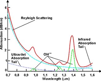
According to Rayleigh scattering loss is inversely proportional to the fourth power of the wavelength i.e., 1 / l4.
Microbend Loss
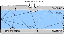
Microbend losses are small microscopic bends of the fiber axis that occur mainly when a fiber is cabled. These bends occur due to external forces, uneven coating applications and improper cabling procedures. Microbends change the path that propagating modes take, as shown in figure.
Macrobend Loss
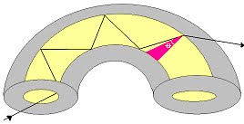
Macrobend loss are bends having a large radius of curvature relative to the fiber diameter.
Mode Coupling Loss
Coupling loss in fiber optics refers to the power loss that occurs when coupling light from one optical device or medium to another