UNIT 2
Wave optics
The Huygens-Fresnel principle states that every point on a wavefront is a cause of wavelets. These wavelets extent out in the forward direction at the similar speed as the source wave.
The new wavefront is a line tangent to all of the wavelets.
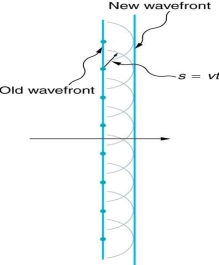
Straight Wavefront: Huygens’s principle applied to a straight wavefront. Individual point on the wavefront emits a semicircular wavelet that changes a distance s=vt. The new wavefront is a line tangent to the wavelets.
Huygens’s Principle:
Figure shows a simple example of the Huygens’s Principle of diffraction. The principle can be revealed with the equation below:
s=Vt
Where, s mean distance, v means propagation speed and t mean time.
Each point on the wavefront emits a wave at speed, v. The emitted waves are semicircular, and happen at t(time) later.
The new wavefront is tangent to the wavelets. This principle works for all wave natures, not just light waves. The principle is helpful in marking reflection, refraction and interference.
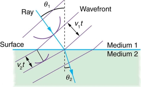
Huygens’s Refraction: Huygens’s principle applied to a straight wavefront traveling from one medium to another where its speed is less.
The ray turns near the perpendicular, since the wavelets have a lower speed in the second medium.
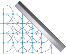
Reflection: Huygens’s principle applied to a straight wavefront striking a mirror. The given wavelets emitted as each point on the wavefront hit the mirror.
The tangent to these wavelets appear that the new wavefront has been reflected at an angle equivalent to the incident angle.
The route of propagation is perpendicular to the wavefront as exposed by the downward pointing arrows.
To produce interference fringes, light from the source has to be divided into two waves which have then to be re-combined.
In an amplitude-division system, a beam splitter is used to split the light into two beams travelling in different directions, which are then superimposed to create the interference pattern.
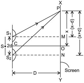
Division of Wave front: In this class, the coherent sources are gotten by separating the input wave front, originating from a common source, by means of mirrors, bi prisms or lenses.
This group of interference involves fundamentally a point source or a narrow slit source. The instruments used to get interference by division of wave front are, Young’s double slit Experiment, the Fresnel biprism, Fresnel mirrors, Lloyd's mirror, lasers, etc.


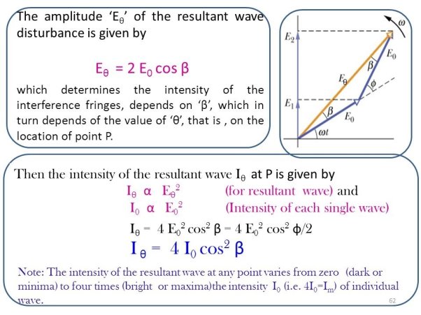

Separation of Amplitude: In this procedure, the amplitude of the input beam is separated into two or more parts both by partial reflection or refraction. Therefore we have coherent beams made by division of amplitude.
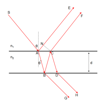

These beams travel dissimilar paths and are lastly brought collected to produce interference. The effects resulting from the superposition of two beams are mentioned to as two beam interference and those resultant from superposition of more than two beams are mentioned to as multiple beam interference.
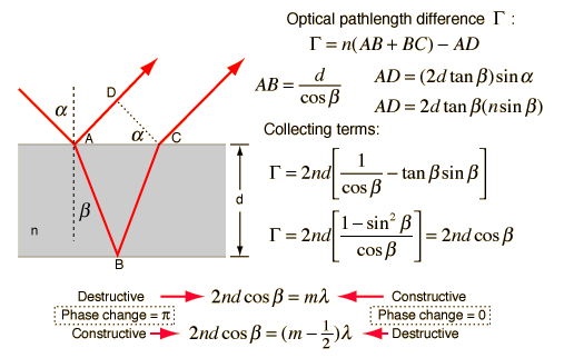
The interference in thin films: Newton's rings and Michelson's interferometer are cases of two beam interference and Fabry-Perot's interferometer is a instance of several beam interference.
In 1801, an English physicist named Thomas Young performed an experiment that strongly inferred the wave-like nature of light.
Because he believed that light was composed of waves, Young reasoned that some type of interaction would occur when two light waves met.
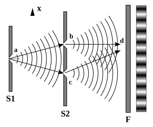
The tutorial initializes with rays from the sun being passed through a single slit in a screen to produce coherent light.
This light is then projected onto another screen that has twin (or double) slits, which again diffracts the incident illumination as it passes through.
The results of interference between the diffracted light beams can be visualized as light intensity distributions on the dark film.
The slider labelled Distance Between Slits can be utilized to vary the distance between the slits and produce corresponding variations in the interference intensity distribution patterns.
Young's experiment was based on the hypothesis that if light were wave-like in nature, then it should behave in a manner similar to ripples or waves on a pond of water.
Where two opposing water waves meet, they should react in a specific manner to either reinforce or destroy each other. If the two waves are in stage (the crests meet), then they should combine to make a greater wave.
In contrast, when two waves meet that are out of step (the crest of one meets the trough of other), the waves should cancel and produce a flat surface in that area.
In order to test his theory, Young developed a resourceful experiment.
Using sunlight diffracted over a small slit as a source of coherent light, he expected the light rays coming from the slit onto another screen containing two slits placed side by side.
Light transient through the slits was then allowable to fall onto a screen. Young detected that when the slits were large, spaced far apart and close to the screen, then two overlapping spots of light formed on the screen.
Though, when he reduced the size of the slits and brought them nearer together, the light passing through the slits and onto the screen formed different bands of colour separated by dark regions in a serial order.
Young invented the term interference fringes to define the bands and understood that these coloured bands could only be formed if light were acting like a wave.
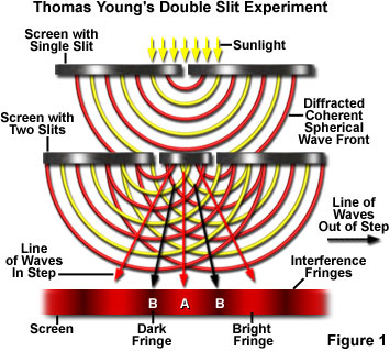
- The basic arrangement of the double slit experiment is showed in Figure 1. Red filtered light resulting from sunlight is first passed over a slit to attain a coherent state.
- Light waves exiting the first slit are then made incident on a pair of slits positioned close together on a second barrier.
- A screen is placed in the region behind the slits to capture overlapped light rays that have passed through the twin slits, and a pattern of bright red and dark interference bands becomes visible on the screen.
- The key to this type of experiment is the mutual coherence between the light waves diffracted from the two slits at the barrier.
- Although Young achieved this coherence through the diffraction of sunlight from the first slit, any source of coherent light (such as a laser) can be substituted for light passing through the single slit.
- The coherent wavefront of light impacting on the twin slits is divided into two new wavefronts that are perfectly in step with each other.
- Light waves from each of the slits must travel an equal distance to reach point A on the screen illustrated in Figure 1, and should reach that point still in step or with the same phase displacement.
- Because the two waves reaching point A possess the necessary requirements for constructive interference, they should add together to produce a bright red interference fringe on the screen.
- In contrast, neither of the points B on the screen is positioned equidistant from the two slits, so light must travel a greater distance from one slit to reach point B than from the other.
- The wave emanating from the slit closer to point B (take for example the slit and point B on the left-hand side of Figure 1) does not have as far to travel to reach its destination as does a wave traveling from the other slit.
- As a consequence, the wave from the closest slit should arrive at point B slightly ahead of the wave from the farthest slit.
- Because these waves will not arrive at point B in phase (or in step with each other), they will undergo destructive interference to produce a dark region (interference fringe on the screen.
- Interference fringe patterns are not restricted to experiments having the double slit configuration, but can be produced by any event that results in the splitting of light into waves that can be cancelled or added together.
- The success of Young's experiment was strong testimony in favour of the wave theory, but was not immediately accepted by his peers.
- The events in place behind phenomena such as the rainbow of colors observed in soap bubbles and Newton's rings (to be discussed below), although explained by this work, were not directly noticeable to those scientists who definitely thought that light propagated as a stream of particles.
- Other types of experiments were later devised and conducted to demonstrate the wave-like nature of light and interference effects.
- Most notable are the single mirror experiment of Humphrey Lloyd and the double mirror and bi-prism experiments devised by Augustin Fresnel for polarized light in uniaxial and birefringent crystals.
- Fresnel concluded that interference between beams of polarized light can only be obtained with beams having the same polarization direction.
- In effect, polarized light waves having their vibration directions oriented parallel to each other can combine to produce interference, whereas those that are perpendicular do not interfere.
- Newton’s rings, in optics, a series of concentric light- and dark-coloured bands observed between two pieces of glass when one is convex and rests on its convex side on another piece having a flat surface. Thus, a layer of air exists between them.
- The phenomenon is caused by the interference of light waves—i.e., the superimposing of trains of waves so that when their crests coincide, the light brightens; but when trough and crest meet, the light is destroyed.
- Light waves reflected from both top and bottom surfaces of the air film between the two pieces of glass interfere. The rings are named after the English 17th-century physicist Sir Isaac Newton, who first investigated them quantitatively.
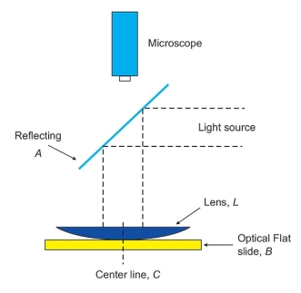
 Sodium fringes
The principle is often used in testing the uniformity of a polished surface by studying the interference pattern the surface makes when placed in contact with a perfectly flat glass surface.
The figure shows contour patterns formed by various surfaces under test.
In the figure, A is produced by a flat surface with point of contact at X. In B and C the test surface is slightly convex, the points of contact indicated by X in each case. An irregular surface may give an interference pattern shown in D, with two points of contact X1 and X2.

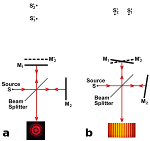
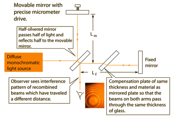
The Michelson interferometer produces interference fringes by splitting a beam of light so that one beam attacks a stationary mirror and the other a transferable mirror. When the reflected beams are carried back organised, an interference pattern outcomes.
Exact distance sizes can be made with the Michelson interferometer by touching the mirror and including the interference fringes which transfer by a reference point.
The distance d related with m fringes is d = mλ/2.
The Michelson interferometer is a common formation for optical interferometry and was developed by Albert Abraham Michelson.
With a beam splitter, a light source is divided into two arms. For each of those light beams is reflected back near the beamsplitter which then combines their amplitudes with the superposition principle.
The resulting interference pattern that is not directed back toward the source is typically directed to some type of photoelectric detector or camera.
For different applications of the interferometer, the two light paths can be with different lengths or incorporate optical elements or even materials under test.
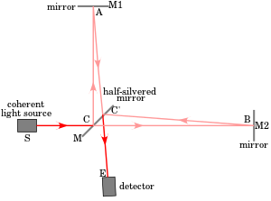
A Michelson interferometer consists minimally of mirrors M1 & M2 and a beam splitter M. In Fig , a source S emits light that hits the beam splitter (in this case, a plate beam splitter) surface M at point C. M is partly reflective, so part of the light is transmitted over to point B while roughly is reflected in the direction of A.
Together beams recombine at point C' to products an interference shape incident on the detector at point E (or on the retina of a person's eye).
If there is a slight angle between the two frequent beams, for example, then an imaging detector will record a sinusoidal fringe pattern as shown in Fig.
If there is perfect spatial arrangement amid the returning beams, then there will not be any such design but rather a constant intensity over the beam in need of on the differential path length; this is challenging, requiring very exact control of the beam paths.
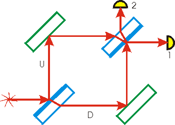
The Mach and Zehnder interferometer developed done one hundred years before, is still used for numerous optical sizes. A figure of the interferometer appears to the right.
The "legend" for the figure is:
Light source: 
Mirror: 
Detector: 
Half-silvered mirror: 
It fits out that in spite of the figure, all of the light from the source ends up at detector 1; no light gets to detector 2. We will demonstrate that this is so.
First, we will need to know the following facts from optics
The "half-silvered" mirror is just a crummy mirror: it only reflects half the light incident on it, refracting the other half through it. Such mirrors are sometimes called one way glass. Sometimes we shall call it a beam splitter.
The speed of light in the air is nearly speed of light c in a vacuum. In terms of the index of refraction n=c/v, where v is the speed of light in the medium, the index of refraction of air is almost exactly 1.
The speed of light in glass is less than c. For most glasses, the index of refraction is on the order of 1.5. Put another way, the speed of light in glass is on the order of two-thirds of the speed of light in a vacuum.
When a light ray is incident on a surface and the material on the other side of the surface has a higher index of refraction (i.e. a lower speed of light than the medium that the light is travelling in), then the reflected light ray is shifted in its phase by exactly one half a wavelength.
The index of refraction of a perfect mirror can be thought of as infinite. Therefore, light reflected by a mirror must be its phase different by one half a wavelength.
When a light ray is incident on a surface and the measurable on the new side of the surface has a lower index of refraction, the reflected light ray does not have its phase different.
When a light ray goes from one medium into another, its direction alterations due to refraction but no phase alteration occurs at the surfaces of the double mediums.
When a light ray travels over a medium, such as a glass plate, its phase will be moved by an amount that depends on the index of refraction of the average and the path length of the light ray over the medium.
Note we have measured the dual detectors 1 and 2 and we have measured the upper path of the light U and the down path of the light D.
We consider the two paths for light arriving at detector 1:
Path "U":
Reflected by the front of the first beam splitter, giving a phase change of one-half a wavelength.
Reflected by the upper-left mirror, giving a further phase change of one-half a wavelength.
Transmitted through the upper-right beam splitter, giving some constant phase change.
Path "D":
Transmitted through the lower-left beam splitter, giving some constant phase change.
Reflected by the front of the lower-right mirror, giving a phase change of one-half a wavelength.
Reflected by the front of the second beam splitter, giving a phase change of one-half a wavelength.
Adding up all the contributions for the two paths, we see that they are the same. Therefore light incoming detector 1 through the two paths is in phase. Therefore we get constructive interference for the light incoming detector 1.
Now we consider light entering detector 2:
Path "U":
Reflected by the front of the first beam splitter, giving a phase change of one-half a wavelength.
Reflected by the upper-left mirror, giving a further phase change of one-half a wavelength.
Transmitted through the second beam splitter, giving some constant phase change.
Reflected by the inner surface of the second beam splitter, giving no phase change.
Transmitted through the beam splitter a second time, giving an additional constant phase change.
Path "D":
Transmitted through the lower-left beam splitter, giving some constant phase change.
Reflected by the front of the lower-right mirror, giving a phase change of one-half a wavelength.
Transmitted through the second beam splitter, giving some constant phase change.
Adding up all these, we see that the total difference between the two paths is that the U path has gone through one additional phase change of one-half a wavelength. So, there will be whole destructive interference and no light will reach detector 2.
Thus we have proved that, regardless of the wavelength of the light, it all goes to detector 1.
The interferometer is used to measure the phase shift of a thin sample of, say, glass. The sample is placed in either the U or D beam.
The phase shift of the sample alters the phase relationships between the two beams that we have just described, and there is no longer complete destructive interference at detector 2.
Measuring the relative amount of light entering detector 1 and detector 2 allows a calculation of the phase shift produced by the sample.
OR
Michelson Interferometer
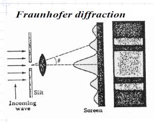
In optics: the Fraunhofer diffraction design is used to model the diffraction of waves when the diffraction shape is observed at a long distance from the diffracting object and also when it is detected at the focal plane of an imaging lens
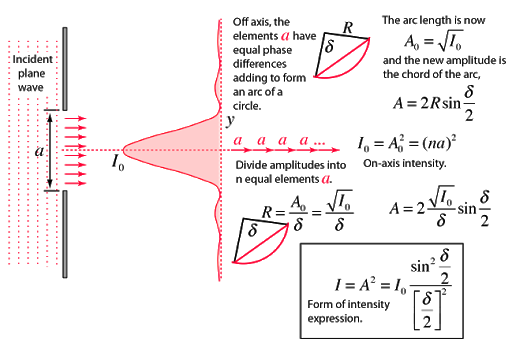
In difference, the diffraction design created close the object, in the near field region, is given by the Fresnel diffraction calculation. 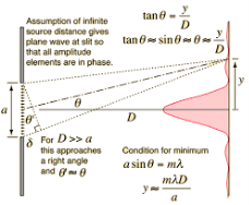
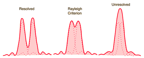
The Rayleigh criterion is the usually recognized criterion for the smallest resolvable feature - the imaging procedure is said to be diffraction-limited when the first diffraction smallest of the image of one source point coincides with the extreme of a different.
 Single slit
 Circular aperture
Application to vision
If altogether quantities of an imaging system are measured to be perfect, then the resolution of some imaging procedure will be limited by diffraction.
Since the single slit appearance above, then when the wavelength is equal to the slit width, the angle for the first diffraction least is 90°.
This means that the wave is spread all the way to the plane of the slit and will not comprise resolvable info near the source of the wave.
This leads to the simplified statement that the boundary of resolution of any imaging procedure is successful to be on the order of the wavelength of the wave used to image it.
Resolving Power of Grating:
It is defined as the capacity of a grating to form separate diffraction maxima of two wavelengths which are very close to each other
It is state by  where
where  is the minimum difference in two wavelengths which are just resolvable by grating and
  is the wavelength of either of them or mean wavelength.
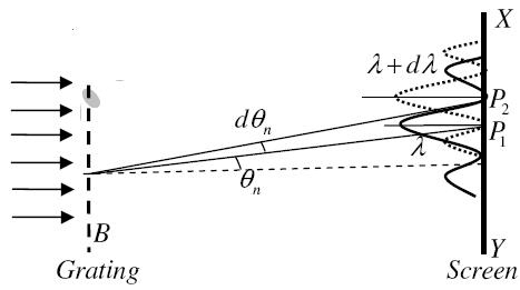
Let AB signify the surface of a plane transmission grating requiring grating element (e+d), N total number of slits. Let a beam of light requiring two wavelengths  and
and  is usually incident on the grating.
Assume P1 is nth primary maximum of a spectral line of wavelength  at an angle of diffraction
  and P2 is the nth primary extreme of wavelength
  at diffracting angle
Allowing to Rayleigh criterion, the two wavelengths will be determined if the principal maximum  of nth order in a direction
  falls over the first least of nth order in the same way
  .
.
Let us consider the first minimum of nth order in the direction  as below.
The principal maximum of  in the
  method is given by

The equation of minima is  where m takes all integers except 0, N, 2N, …, nN, because for these values of m, the condition for maxima is satisfied. Thus first minimum adjacent to nth principal maximum in the direction
  can be obtained by substituting the value of ‘m’ as (nN+1). Therefore, the first minimum in the direction of
  is given by


The principal maximum of  in direction
  is specified by

Dividing eqn (2.47) by eqn (2.48), we get


Thus the resolving power is directly proportional to
(i) The order of the spectrum ‘n’
(ii) The total number of lines on the grating ‘N’
- When a planar wave passes through the slit it bends or creates a spherical wave front. This means that light is scattered in all directions.
- Suppose the material surface is irregular then the resulting planar waves scatter randomly and no interference pattern emerges at macroscopic level.
- In case material posses surface patterns, the regularity of patterns produces diffracted wave fronts to interact in a repeating or non-random way.
- This effect is termed as diffraction grating. Here some wavelengths of light are greatly amplified, while some will be cancelled out.
- The Grating Equation
- The dispersion of a grating is governed by the grating equation, usually written as:

- Where: n is the order of diffraction,
- λ is the diffracted wavelength
- d is the grating constant (the distance between successive grooves)
- θi is the angle of incidence measured.
Resolving Power:
It is defined as the inverse of the distance or angular separation between two objects which can be just resolved when viewed through the optical instrument.
Resolving Power of Telescope:
In telescopes, very close objects such as binary stars or individual stars of galaxies subtend very small angles on the telescope. To resolve them we need very large apertures. We can use Rayleigh’s to determine the resolving power. The angular separation between two objects must be
△θ = 1.22 λd
Resolving power = 1△θ = d1.22 λ
Thus, higher the diameter d, better the resolution. The best astronomical optical telescopes have mirror diameters as large as 10m to achieve the best resolution. Also, larger wavelengths reduce the resolving power and consequently radio and microwave telescopes need larger mirrors.
Conditions for maxima or minima