Unit 2
1 and 3 Phase AC Circuit
When an electric current flow through a wire or conductor, a circular magnetic field is created around the wire and whose strength is related to the current value.
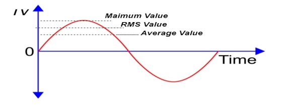
Average Value:
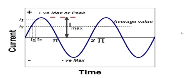
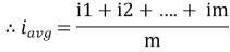
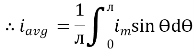
The arithmetic mean of all the value over complete one cycle is called as average value
 =
= 
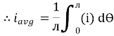
For the derivation we are considering only hall cycle.
Thus  varies from 0 to ᴫ
i = Im Sin
Solving
We get

Similarly, Vavg=
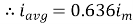
The average value of sinusoid ally varying alternating current is 0.636 times maximum value of alternating current.
RMS value: Root mean square value
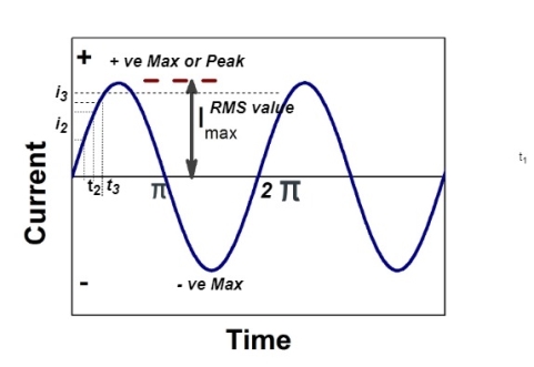
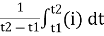
The RMS value of AC current is equal to the steady state DC current that required to produce the same amount of heat produced by ac current provided that resistance and time for which these currents flows are identical.
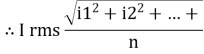
I rms = 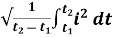
Direction for RMS value:
Instantaneous current equation is given by
i = Im Sin 
But 
I rms = 
= 
=
=
Solving
=
=
Similar we can derive
V rms=  or 0.707 Vm
 the RMS value of sinusoidally alternating current is 0.707 times the maximum value of alternating current.
Peak or krest factor (kp) (for numerical)
It is the ratio of maximum value to rms value of given alternating quantity
Kp = 
 Kp =
Kp = 
 Kp = 1.414
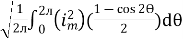
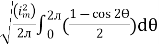
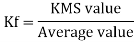
Form factor (Kf): For numerical “It is the ratio of RMS value to average value of given alternating quality”.

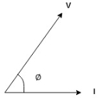
The phase of an alternating quantity at any instant in time can be represented by a phasor diagram, so phasor diagrams can be thought of as “functions of time”. A complete sine wave can be constructed by a single vector rotating at an angular velocity of ω = 2πƒ, where ƒ is the frequency of the waveform. Then a Phasor is a quantity that has both “Magnitude” and “Direction”.
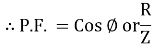
- As we know power factor is cosine of angle between voltage and current
i e P.F. = Cos 
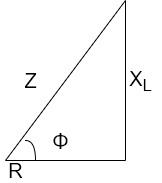
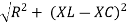
In other words also we can derive it from impedance triangle
Now consider Impedance triangle in R – L- ckt.
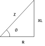
From  now Cos
  = power factor =
 power factor = Cos
  or
or 
Two impedances in parallel
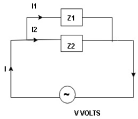
I1 an I2 can be founded using current division rules
It states that the current in one branch is the products, ratio of total current and opposite branch (impedance / reactance / resistance) to the total (impedance / reactance / resistance)
 above ckt. Can be found using following steps
- Find total impedance Z1 + Z2 = Z using conversion from polar to rectangular (if given Z1/Z2 is in polar form) and then finding Z = Z1 + Z2
- Find total current I using formulas

- Then find I1 using current division rule
 or Z
or Z - Find I2 using current division Rule
 or z
or z
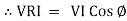
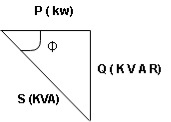
- Apparent power : (S):- it is defined as product of rms value of voltage (v) and current (I), or it is the total power/maximum power
S= V × I
Unit - Volte- Ampere (VA)
In kilo – KVA
2. Real power/ True power/Active power/Useful power : (P) it is defined as the product of rms value of voltage and current and the active component or it is the average or actual power consumed by the resistive path (R) in the given combinational circuit.
It is measured in watts
P = VI  Φ watts / KW, where Φ is the power factor angle.
3. Reactive power/Imaginary/useless power [Q]
It is defined as the product of voltage, current and sine B and I
Therefore,
Q= V.I  Φ
Φ
Unit –V A R
In kilo- KVAR
As we know power factor is cosine of angle between voltage and current
i.e. Φ.F= CosΦ
In other words also we can derive it from impedance triangle
Now consider Impedance triangle in R.L.ckt
From triangle ,
Now  Φ – power factor=
Power factor =  Φ or
Φ or 
3 Basic element of AC circuit.
1] Resistance
2] Inductance
3] Capacitance
Each element produces opposition to the flow of AC supply in forward manner.
Reactance
- Inductive Reactance (XL)
It is opposition to the flow of an AC current offered by inductor.
XL = ω L But ω = 2 ᴫ F
 XL = 2 ᴫ F L
It is measured in ohm
 XL∝FInductor blocks AC supply and passes dc supply zero
2. Capacitive Reactance (Xc)
It is opposition to the flow of ac current offered by capacitor
Xc = 
Measured in ohm
 Capacitor offers infinite opposition to dc supply
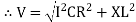
Impedance (Z)
The ac circuit is to always pure R pure L and pure C it well attains the combination of these elements. “The combination of R1 XL and XC is defined and called as impedance represented as
Z = R +i X
Ø = 0
 only magnitude
R = Resistance, i = denoted complex variable, X =Reactance XL or Xc
Polar Form
Z =  L I
L I
Where  =
=
 Measured in ohm
Power factor (P.F.)
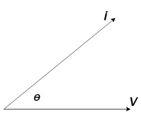
It is the cosine of angle between voltage and current
If Ɵis –ve or lagging (I lags V) then lagging P.F.
If Ɵ is +ve or leading (I leads V) then leading P.F.
If Ɵ is 0 or in phase (I and V in phase) then unity P.F.
Ac circuit containing pure resisting
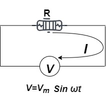
Consider Circuit Consisting pure resistance connected across ac voltage source
V = Vm Sin ωt ①
According to ohm’s law i =  =
= 
But Im = 
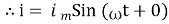 ②
②
Phases diagram
From ① and ② phase or represents RMD value.
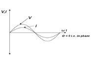
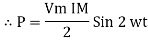
Power P = V. i
Equation P = Vm sin ω t Im sin ω t
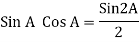
P = Vm Im Sin2 ω t
P =  -
- 

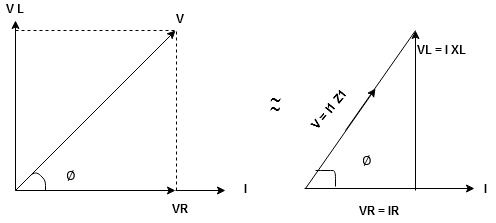
Constant fluctuating power if we integrate it becomes zero

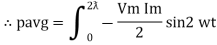
Average power
Pavg = 
Pavg = 
Pavg = Vrms Irms
Power form [Resultant]
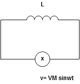
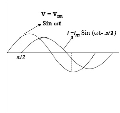
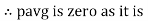
Ac circuit containing pure Inductors
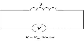
Consider pure Inductor (L) is connected across alternating voltage. Source
V = Vm Sin ωt
When an alternating current flow through inductance it set ups alternating magnetic flux around the inductor.
This changing the flux links the coil and self-induced emf is produced
According to faradays Law of E M I
e = 
At all instant applied voltage V is equal and opposite to self-induced emf [ lenz’s law]
V = -e
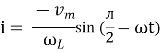
 =
= 
But V = Vm Sin ωt
 dt
dt
Taking integrating on both sides
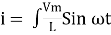 dt
dt
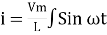 dt
dt
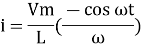
 (-cos
(-cos  )
)
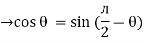
But sin (– ) = sin (+
 )
)
 sin (
sin ( -
-  /2)
/2)
And Im= 
 /2)
/2)
 /2
/2
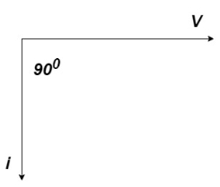
= -ve
= lagging
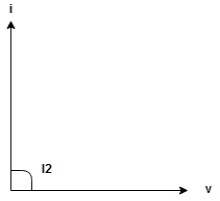
= I lag v by 900
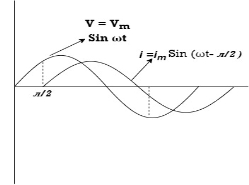
Phasor:
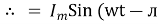
Power P = Ѵ. I
= Vm sin wt Im sin (wt  /2)
/2)
= Vm Im Sin wt Sin (wt –  /s)
/s)
 ①
①
And
Sin (wt -  /s) = - cos wt ②
Sin (wt –  ) = - cos
 sin 2 wt from ① and ②
The average value of sin curve over a complete cycle is always zero
 Pavg = 0
Ac circuit containing pure capacitors:
Consider pure capacitor C is connected across alternating voltage source
Ѵ = Ѵm Sin wt
Current is passing through capacitor the instantaneous charge ɡ produced on the plate of capacitor
ɡ = C Ѵ
ɡ = c Vm sin wt
The current is rate of flow of charge

i= (cvm sin wt)
i = c Vm w cos wt
Then rearranging the above eqth.
i =  cos wt

 = sin (wt +
  X/2)
X/2)
i =  sin (wt + X/2)
But 
 X/2)
X/2)

= leading
= I leads V by 900
Waveform :
Phase
Power P= Ѵ. i
= [Vm sinwt] [ Im sin (wt + X/2)]
= Vm Im Sin wt Sin (wt + X/2)]
 (cos wt)
 to charging power waveform [resultant].
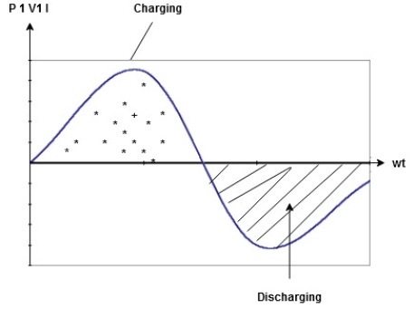
Series R-L Circuit
Consider a series R-L circuit connected across voltage source V= Vm sin wt
As some I is the current flowing through the resistor and inductor due do this current voltage drops arcos R and L R  VR = IR and L
  VL = I X L
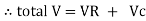
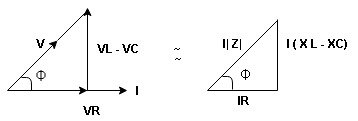
 Total V = VR + VL
V = IR + I X L  V = I [R + X L]


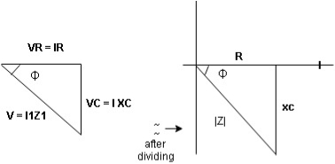
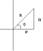
Take current as the reference phasor : 1) for resistor current is in phase with voltage 2) for Inductor voltage leads current or current lags voltage by 90 0.
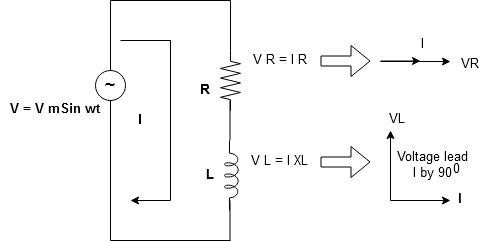
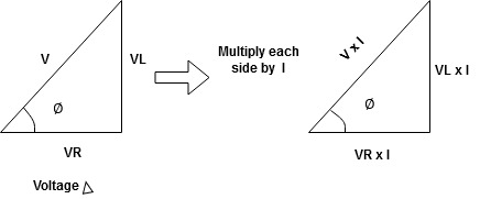
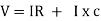
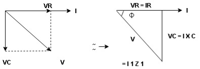
For voltage triangle
Ø is power factor angle between current and resultant voltage V and
V = 
V = 

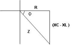
Where Z = Impedance of circuit and its value is  =
= 
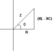
Impedance Triangle
Divide voltage triangle by I
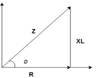
Rectangular form of Z = R+ixL
And polar from of Z =  L +
L + 
(+ j X L +  because it is in first quadrant )
Where  =
= 
 + Tan -1
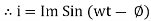
Current Equation :
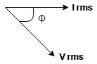
From the voltage triangle we can sec. That voltage is leading current by  or current is legging resultant voltage by
Or i =  =
=  [ current angles - Ø )
Resultant Phasor Diagram from Voltage and current eqth.
Wave form

Power equation
P = V .I.
P = Vm Sin wt Im Sin wt – Ø
P = Vm Im (Sin wt) Sin (wt – Ø)
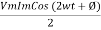
P =  (Cos Ø) - Cos (2wt – Ø)
Since 2 sin A Sin B = Cos (A-B) – Cos (A+B)
P =  Cos Ø -
  Cos (2wt – Ø)

①②
Average Power
Pang =  Cos Ø
Cos Ø
Since ② term become zero because Integration of cosine come from 0 to 2ƛ
 pang = Vrms Irms cos Ø watts.
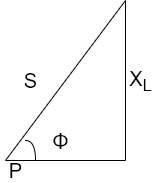
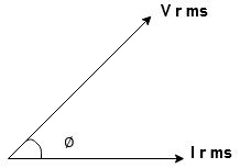
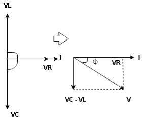
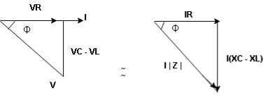
Power Triangle :
From 
VI = VRI + VLI B
Now cos Ø in  A =
A = 
 ①
①
Similarly Sin  =
= 


Apparent Power Average or true Reactive or useless power
Or real or active
-Unit (VI) Unit (Watts) C/W (VAR) denoted by (Ø)
Denoted by [S] denoted by [P]
Power  for R L ekt.
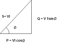
Series R-C circuit
V = Vm sin wt
VR

 I
I
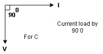
- Consider a series R – C circuit in which resistor R is connected in series with capacitor C across a ac voltage so use V = VM Sin wt (voltage equation).
- Assume Current I is flowing through
R and C  voltage drops across.
R and C  R
R  VR = IR
And C  Vc = I
 c
c

 V =
V =  lZl
lZl
Voltage triangle : take current as the reference phasor 1) for resistor current is in phase with voltage 2) for capacitor current leads voltage or voltage lags behind current by 900
Where Ø is power factor angle between current and voltage (resultant) V
And from voltage
V = 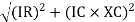
V = 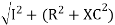
V = 
V =  lZl
lZl
Where Z = impedance of circuit and its value is lZl = 
Impendence triangle :
Divide voltage  by
by  as shown
Rectangular from of Z = R - jXc
Polar from of Z = lZl L - Ø
( - Ø and –jXc because it is in fourth quadrant ) where
LZl = 
And Ø = tan -1 
Current equation :
From voltage triangle we can see that voltage is lagging current by Ø or current is leading voltage by Ø
 i = IM Sin (wt + Ø) since Ø is +ve
Or i =  for RC
 LØ [ resultant current angle is + Ø]
Resultant phasor diagram from voltage and current equation
Resultant wave form :

Power Equation :
P = V. I
P = Vm sin wt. Im Sin (wt + Ø)
= Vm Im sin wt sin (wt + Ø)
2 Sin A Sin B = Cos (A-B) – Cos (A+B)
 -
- 
Average power
Pang =  Cos Ø
Cos Ø
Since 2 terms integration of cosine wave from 0 to 2ƛ become zero
 2 terms become zero
 pang = Vrms Irms Cos Ø
Power triangle RC Circuit:
R-L-C series circuit
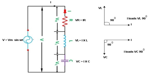
Consider ac voltage source V = Vm sin wt connected across combination of R L and C. When I flowing in the circuit voltage drops across each component as shown below.
VR = IR, VL = I  L, VC = I
  C
C
- According to the values of Inductive and Capacitive Reactance I e XL and XC decides the behaviour of R-L-C series circuit according to following conditions
① XL> XC, ② XC> XL, ③ XL = XC
① XL > XC: Since we have assumed XL> XC
 Voltage drop across XL> than XC
 VL> VC A
- Voltage triangle considering condition A

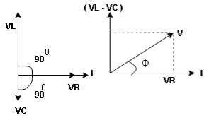
VL and VC are 180 0 out of phase .
Therefore cancel out each other
 Resultant voltage triangle
Now V = VR + VL + VC c phasor sum and VL and VC are directly in phase opposition and VL
 VC
VC their resultant is (VL - VC).
From voltage triangle
V = 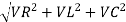
 V =
V = 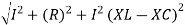
 V = I
V = I 

Impendence  : divide voltage
Rectangular form Z = R + j (XL – XC)
Polor form Z =  l + Ø B
Where  =
= 
And Ø = tan-1 
- Voltage equation : V = Vm Sin wt
- Current equation
i =  from B
i =  L-Ø C
L-Ø C
As VL VC the circuit is mostly inductive and
  I lags behind V by angle Ø
 Since i =
  L-Ø
L-Ø
 i = Im Sin (wt – Ø) from c
- XC
 XL :Since we have assured XC
  XL
XL
 the voltage drops across XC
  than XL
 XC
XC  XL (A)
 voltage triangle considering condition (A)
 Resultant Voltage
Now V = VR + VL + VC  phases sum and VL and VC are directly in phase opposition and VC
 VL
VL  their resultant is (VC – VL)
From voltage 
V = 
V = 
 V =
V = 
 V =
V = 

 Impedance
  : Divide voltage
- Rectangular form : Z + R – j (XC – XL) – 4th qurd
Polar form : Z =  L -
L -
Where 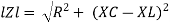
And Ø = tan-1 – 
- Voltage equation : V = Vm Sin wt
- Current equation : i =
 from B
 - i =
 L+Ø C
L+Ø C
As VC  the circuit is mostly capacitive and
  leads voltage by angle Ø
Since i =  L + Ø
L + Ø
 Sin (wt – Ø) from C
- Power
 :
:
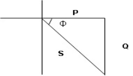
- XL= XC (resonance condition):
ɡȴ XL= XC then VL= VC and they are 1800 out of phase with each other  they will cancel out each other and their resultant will have zero value.
Hence resultant V = VR and it will be in phase with I as shown in below phasor diagram.
From above resultant phasor diagram
V =VR + IR
Or V = I  lZl
lZl
Because lZl + R
Thus Impedance Z is purely resistive for XL = XC and circuit current will be in phase with source voltage.

 Since VR= V Øis zero when XL = XC
  power is unity
Ie pang = Vrms I rms cos Ø = 1 cos o = 1
Maximum power will be transferred by condition. XL = XC
3 Phase AC Circuit
- Poly phase one which produces many phase simultaneously
- Instead of saying poly phase we use 3 ɸ supply there for 3 ɸ system
- Generation of electrical supply is 3 ɸ only using alternator (AC generator ) by 3 separate winding placed 1200 a part from each other one winding for I phase
 3 windings
3 phase =  = 1290 apart each winding
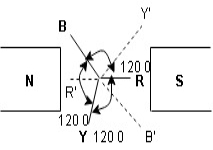
Here R is the reference phase globally in generation of 3 Ø ac
Ø = 0
Y is the 2nd phase generated and placed apart from R phase Ø = -1200
B is the 3rd phase generated and placed apart from R phase Ø = -2400
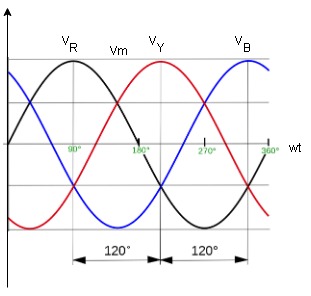
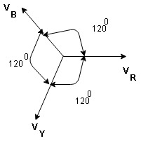
4.2 Phasor Diagram :
Equation
VR = Vm Sin wt
VY = Vm Sin (wt-1200)
VB = sin (wt – 2400)
Or VB = Vm sin (wt + 1200)
- Advantages of 3 Ø system over single phase
- More output : for same size the output of 3Ø machine is always higher than single 1 Ø phase machine.
- Smaller size : for producing same output the size of 3 phase machine is always smaller than of single phase machine
- 3 phase motor are self starting as the 3 Ø ac supply is capable of producing a rotating magnetic file when applied are self starting 1 Ø motor need additional starter winding
- More power is transmitted : in the transmitted system it is possible to transmitted more power using 3 Ø system rather than 1 Ø system, by using conductor of same cross sectional .
- Smaller cross sectional area of conductor
ɡȴ same amount of power is to transmitted than cross sectional area of conductor used for 3 Ø system is small as compared to that for single Ø system.
The sequence in which the 3 phase reach their maximum +ve values Sequence is R-Y-B 3 colours used to denoted 3 phase are red’, yellow, blue.
The direction of rotation of 3 Ø machines depends on phase sequence. ɡȴ the phase sequence is changed ie R-B-Y than the direction of rotation will be reversed.
Balanced load : balanced load is that in which magnitude of all impedance connected in the load are equal and the phase angle of them are also equal
Ie Z1  Z2
Z2  Z3 then it is unbalanced load
- Line values and phase Values :
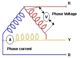
- Line Values : ɡȴ RYB are supply lines then the voltage measured between any 2 Line is called as line voltage and current measured in the supply line is called as line current .
2. Phase Value : the voltage measured across a single winding or phase is called as phase voltage and the current measured on the single winding or phase is called as line current.
Derive
Relation between line value and phase value of voltage and current for balanced (ʎ) star connected load (load can be resistive , Inductive or capacitive)
For capacitive load
Consider a 3 Ø balanced star connected balanced load capacitive
- Line Value
Line voltage = VRY = VYB = VBR = VL
Line current = IR = IY = IB = IL
Phase value
Phase voltage = VRN = VYN = VBN = Vph
Phase current = VRN = VYN = VBN = Vph
Since for a balanced star connected load the line current is the same current flowing in the phase  the line current = phase current IR = IY = IB = IRN = IBN = IYN
 dor star connected load IN = Ipn
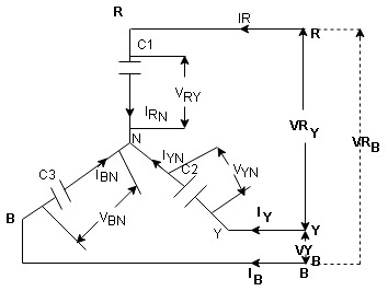
- Since the line voltage differ from phase voltage we can relate the line value of voltage with phase value of voltage
Referring current diagram
 =
=  +
+ 
Bar indicates vector addition
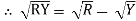
 =
= 
 =
=  -
-  …..①
…..①
Instead of writing  or
or  we can write VR and VY for practical purpose
Similarly other line voltage can be writing as follows.
(Resultant)
 =
=  -
-  …..②
…..②

 =
=  -
- 
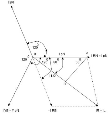
- Phasor Diagram :
Consider equation …..①
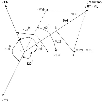
NOTE : We are getting resultant line voltage by subtracting phase voltage  take phase voltage at reference phase as shown
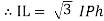
Cos 300 = 
 =
= 
 VL =
VL = 
 phase for ʎ connected capacitive balance load
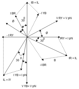
- Phasor Diagram
Consider equation ①
Note : we are getting resultant line current IR by subtracting 2 phase currents IRY and IBR  take phase currents at reference as shown
Cos 300 = 
 =
= 
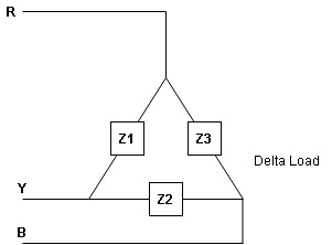
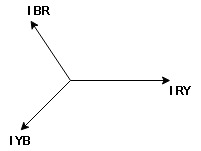
- Complete phases diagram for delta connected balanced Inductive load.
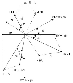
Phase current IYB lags behind VYB which is phase voltage as the load is inductive
- Power relation for delta load star power consumed per phase
PPh = VPh IPh Cos Ø
For 3 Ø total power is
PT= 3 VPh IPh Cos Ø …….①
For star
VL and IL = IPh (replace in ①)
 PT = 3
  IL Cos Ø
 PT = 3
  VL IL Cos Ø – watts
For delta
VL = VPh and IL =  (replace in ①)
PT = 3VL
= 3VL  Cos Ø
Cos Ø
 PT
PT VL IL Cos Ø – watts
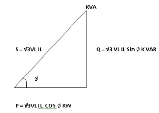
Total average power
P =  VL IL Cos Ø – for ʎ and
  load
load
K (watts)
Total reactive power
Q =  VL IL Sin Ø – for star
  delta load
K (VAR)
Total Apparent power
S =  VL IL – for star
  delta load
K (VA)
- Power triangle
- Relation between power
In star and power in delta
Consider a star connected balance load with per phase impedance ZPh
We know that for
VL = VPh andVL =  VPh
VPh
Now IPh = 
 VL = =
And VPh = 
 IL =
IL =  ……①
……①
Pʎ =  VL IL Cos Ø ……②
Replacing ① in ② value of IL
 Pʎ =
Pʎ =  VL IL
VL IL  Cos Ø
Cos Ø
 Pʎ =
Pʎ =  ….A
….A
- Now for delta
IPh = 
 IPh = =
And IL =  IPh
IPh
 IL =
IL =  X
X  …..①
…..①
P =
=  VL IL Cos Ø ……②
Replacing ② in ① value of IL
P =
=  Cos Ø
Cos Ø
 P
P =
=  …..B
…..B

Pʎ from …A
 …..C
…..C
 =
=  P
P
We can conclude that power in delta is 3 time power in star from …C
Or
Power in star is  time power in delta from ….D
- Step to solve numerical
- Calculate VPh from the given value of VL by relation
For star VPh = 
For delta VPh = VL
2. Calculate IPh using formula
IPh = 
3. Calculate IL using relation
IL = IPh - for star
IL =  IPh - for delta
4. Calculate P by formula (active power)
P =  VL IL Cos Ø – watts
5. Calculate Q by formula (reactive power)
Q =  VL IL Sin Ø – VAR
6. Calculate S by formula (Apparent power)
S =  VL IL– VA


