Unit 4
Electrical Machine
Construction details of D.C. Machine
Whether machine is D.C. Generator or motor the construction basically remains the same.
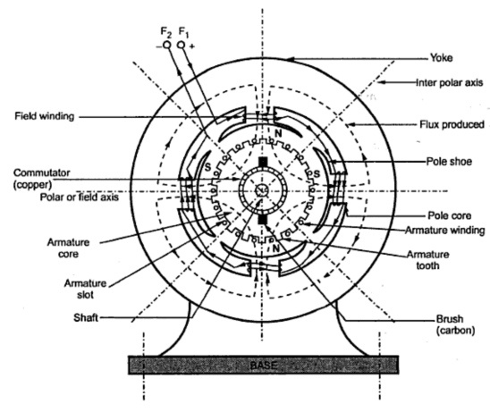
A cross section of typical D.C. Machine
1)Yoke
a)Functions
1. It serve the purpose of outermost cover of the D.C. Machine. So that the insulating materials get protected from harmful atmospheric elements like moisture. Dust and various gases like  , acidic fumes etc.
2. It provides mechanical support to the poles.
3. It forms a part of the magnetic circuit.
It provides a path of low reluctance for magnetic flux. The low reluctance path is important to avoid wastage of power to provide same flux large current and hence the power is necessary if the path has high reluctance to produce the same flux.
4.Choice of material:- It is prepared by using cast iron, silicon steel is used which provides high permeability i.e. low reluctance and gives good mechanical strength.
2) Poles
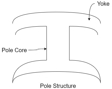
Pole structure
Each Pole is divided into two parts namely
- Pol core
- Pole shoe
Functions of pole core and pole shoe:-
- Pole core basically carries a field winding which is necessary to produce the flux.
- It directs the flux produced through air gap to armature core to the next pole.
- Pole shoe enlarge the area of armature core to come across the flux, which is necessary to produce larger induced e.m.f. To achieve this, sports shoe has been given a particular shape.
Choice of material:-
It is made up of magnetic material like cast iron or cast steel.
As it requires a definite shape and size, laminated construction is used. The laminations of required size and shape are stamped together to get a pole which is then bolted to the yoke.
3) Field Winding (
The field winding is wound on the pole core with a definite direction.
a)Functions:-
To carry current due to which pole core on which the field winding is placed behaves as an electromagnet, producing necessary flux.
As it helps in producing the magnetic field i.e. exciting the poles as an electromagnet it is called Field winding or Exciting winding.
b) Choice of material:-
It has to carry current hence obviously made up of some conducting material.
So aluminium or copper is the choice. But field coils are required to take four types of shape and bent about pole core and copper has good pliability i.e. it can be bend easily. So copper is the proper choice .field winding is divided into various coils called field coils. These are connected in series with each other and wound in such direction around pole cores, such that alternate 'N' and 'S' poles are formed.
The total number of poles is denoted as P.
4) Armature
The armature is further divided into two parts namely
- Armature core
- Armature winding
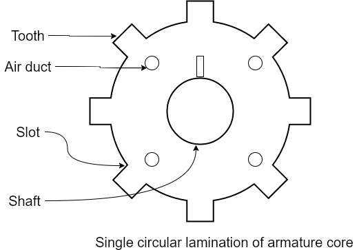
1.Armature core:- Armature core is cylindrical in in shape mounted on the shaft. It consists of slots on its periphery and air ducts to permit the air flow through armature which serves cooling purpose.
a) Functions-
1) Armature core provides house for armature winding i.e. armature conductors.
2)To provide the path of low reluctance to the magnetic flux produced by the field winding.
b) Choice of material:-
As it has to provide a low reluctance path to the flux, it is made up of magnetic material like cast iron or cast steel.
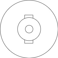
It is made up of laminated construction to keep Eddy current loss as low as possible. A single circular lamination used for the construction of armature core is shown in figure.
3. Armature winding
Armature winding is nothing but the interconnection of the armature conductors placed in the slots provided on the armature core periphery.
When the armature is rotated in case of generator magnetic flux gets cut by armature conductors and e.m.f gets induced in them.
a)Functions
1) curvatures of e.m.f takes place in the armature winding in case of generators.
2) To carry the current supplied in case of D.C. Motors.
3) To do the useful work in the external circuit.
b) Choice of Material:-
As armature winding carries entire current which depends on external load, it has to be made up of conducting material which is copper.
5.Commutator
The basic nature of e.m.f in the armature conductors is alternating. This needs verification in case of D.C. Generator, which is possible by a device called commutator.
a)Functions:
1)To facilitate the collection of current from the armature conductors.
2) To convert internally developed alternating e.m.f to unidirectional (D.C.) e.m.f.
3) To produce unidirectional torque in case of motors
b) Choice of Material:-
As it collects current from armature, it is also made up of copper segments.
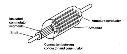
It is cylindrical in shape and is made up of wedge-shaped segments of hand drawn high conductivity copper .the segments are insulated from each other by thin layer of Mica.
Each commutator segment is connected to the armature conductor by means of copper lug or strip. This construction is shown in figure above.
6. Brushes and Brush Gear
Brushes are stationary and resting on the surface of the commutator.
a)Function-
To collect current from computer and make it available to stationary external circuit.
b) Choice of Material:-
Brushes are normally made up of soft material like carbon.
To avoid wear and tear of commutator the brushes are made up of soft material like carbon.
7) Bearings
Ball bearings are usually used as they are more reliable. For heavy duty machines roller bearing are preferred.
- Synchronous motor: Stator poles rotate at the synchronous speed (Ns) when fed with a three-phase supply. The rotor is fed with a DC supply. The rotor needs to be rotated at a speed near to the synchronous speed during starting. If done so, the rotor poles get magnetically coupled with the rotating stator poles, and thus the rotor starts rotating at the synchronous speed.
- Synchronous motor always runs at a speed equal to its synchronous speed.
i.e. Actual speed = Synchronous speed
or N = Ns = 120f/P
- Synchronous motor always runs at a speed equal to its synchronous speed.
- Induction motor: When the stator is fed with two or three phase AC supply, a Rotating Magnetic Field (RMF) is produced. The relative speed between stator's rotating magnetic field and the rotor will cause an induced current in the rotor conductors. The rotor current gives rise to the rotor flux. According to Lenz's law, the direction of this induced current is such that it will tend to oppose the cause of its production, i.e. relative speed between stator's RMF and the rotor. Thus, the rotor will try to catch up with the RMF and reduce the relative speed.
- Induction motor always runs at a speed which is less than the synchronous speed.
i.e. N < Ns
- Induction motor always runs at a speed which is less than the synchronous speed.
Consider- 3Ф slip ring I.M
Cut section diagram:-
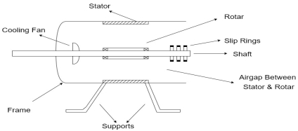
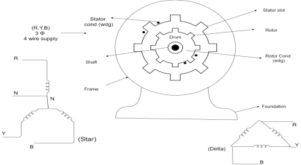
The induction motor has following important parts:-
- Stator :- it is the stationary part of induction motor and it is one of important part in induction motor.
- Rotor:- the rotor is the rotating part of induction motor which consists of rotor wdg.
- Stator winding:- this wdg. Is mounted on devastator and it generates the RMF i.e. rotating magnetic field.
- Rotor winding:- rotor winding is used to rotate the shaft of motor. This wdgis provided on rotor
- Frame :- it provides the mechanical support to the motor. It is the outer covering of motor. It protects the internal parts of motor from damage.
- Shaft:- shaft is used to connect to the load and four rotation.
- Slip rings and brushes:- slip rings are mounted on the shaft which is connected with brushes from which connection is given to the external resistant or rheostat
- Cooling fan:- this is provided for cooling purpose of motor and its internal parts.
Principle of operation of induction motor:
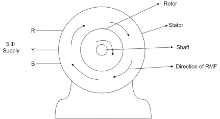
- When the 3Ф A.C supply is connected across the stator of induction motor, the current starts flowing through the stator wdg. i.ethe stator condition.
- Due to this current of flux (Ф) is established in the stator wdg. This flux (Ф) is alternating (changing) in nature. Thus this flux links with the rotor also, and a a Rotating Magnetic Field(RMF) is produced.
- This flux (Ф) induces emf in the rotor also. The RMF is produced in the air gap between stator and rotor.
- The rotor is rotating part which is till stationary, show the rotating magnetic field is cut by stationary rotor and an EMF is induced in the rotor winding. According to faraday's law of EMI the rotor EMF gives the rise to rotor current which opposes the main cause producing it according Lenz's law.
Types of induction motor:
Two main types depending upon the rotor
- Squirrel cage induction motor (squirrel cage rotor)
- Slip ring induction motor(slip ring or wound rotor)
Induction motor are also available in 1Ф supply i.e.
1. Resistance split phase induction motor
2. Capacitor start induction motor
3. Capacitor start capacitor run induction motor
4. 1Ф induction motor i.e. A.C series motors
5. Shaded pole induction motor
Torque equation of induction motor:-
Torque produced in induction motor depends upon the following factors
1.The rotor power factors ( CosФ) under running condition
2.The rotor current under running condition
3. The part of RMF which induces EMF in rotor wdgi.e. flux (Ф)
We can mathematically say that,
 , As per DC (M) equation
But in case of induction motor
Suffix 1 -> used for stator/stator parts (qty)
Suffix 2-> used for rotor/rotor parts(qty)
Therefore,  ----(1)
 = flux that induces the EMF in rotor
 = rotor current under running condition
 = P.F of rotor
But, stator vtg
 also i.e
 ----(2)
Transformation ratio i.e. given by 
Therefore,
 and hence
 also
also
 at slip ’S’ is given by
And also  at slip ‘S’ is
  =S.
=S.
Hence  in equation can be replaced by
i.e.  U
U
 =
= ----(3)----(
 )
)
4 =
= ------(4)
Substract (3) and (4) into (1) equation we get,


 (N-m) , Torque equation of I.M.


At starting condition slip S=1
So, 
- We know that, an induction motor consists of two assemblies i.e., rotor and stator.
- The interaction of currents that is flowing in rotor and stator bars generate a torque. In an actual operation, the rotor speed always lags the magnetic field’s speed, thereby allowing the rotor bars to cut the magnetic lines of force and produce torque. This speed difference is called slip.
- Therefore, the difference between the synchronous speed Ns of the rotating stator field and the actual rotor speed N is called slip.
- The slip increase with load and is necessary for torque production. Slip speed is equal to the difference between rotor speed and synchronous speed. Percent slip is slip multiplied by 100.
- Slip is expressed as a percentage of synchronous speed i.e.,
% of slip, s=(Ns-N/Ns) *100
- The quantity Ns-N is sometimes called as slip speed.
- When the rotor is stationary, slip s=1 or 100%
- In an induction motor, change in slip from no load to full load is hardly 0.1%to 3% so that it is essentially a constant speed motor.
- Three phase induction motor is a particular form of transformer which has secondary winding rotating. In transformer, the frequency of primary and secondary winding is same but in induction motor the frequency of emf induced in rotor depends on slip.
Rotor emf frequency=s*sf,
Where, sf is frequency of applied voltage to stator.
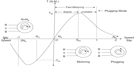
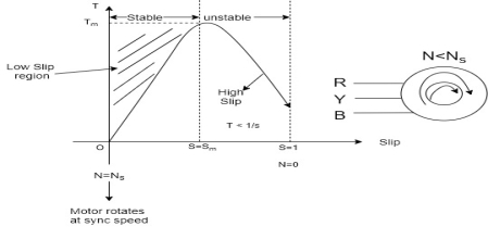
Torque slip region for stable regimen

S= small  -> Negligible


Unstable:-

 , neglect
 = Constant value
 =high slip region
 and vice versa

Various Torques ;
 at starting s=1 and 4N =0
 ----------slip is
  i.e..
i.e.. 
Total Torque


The main applications of the three types of direct current motors are given below.
Series Motors
The series DC motors are used where high starting torque is required, and variations in speed are possible. For example – the series motors are used in Traction system, Cranes, air compressors, Vacuum Cleaner, Sewing machine, etc.
Shunt Motors
The shunt motors are used where constant speed is required and starting conditions are not severe. The various applications of DC shunt motor are in Lathe Machines, Centrifugal Pumps, Fans, Blowers, Conveyors, Lifts, Weaving Machine, Spinning machines, etc.
Compound Motors
The compound motors are used where higher starting torque and fairly constant speed is required. The examples of usage of compound motors are in Presses, Shears, Conveyors, Elevators, Rolling Mills, Heavy Planners, etc.
The small DC machines whose ratings are in fractional kilowatt are mainly used as control device such in Techno generators for speed sensing and in Servo motors for positioning and tracking.