UNIT 3
FLUID
Anything that can flow is a fluid. The water we drink, the air we breathe is all examples of fluids. Essentially, all liquids and gases are fluids. Though each fluid is different from others in terms of composition and specific qualities, there are some properties which every fluid shares.
These properties can be broadly categorized under:
- Kinematic properties: These properties help in understanding the fluid motion. Velocity and acceleration are the kinematic properties of the fluids.
- Thermodynamic properties: These properties help in understanding the thermodynamic state of the fluid. Temperature, density, pressure, and specific enthalpy are the thermodynamic properties of the fluids.
- Physical properties: These properties help in understanding the physical state of the fluid such as colour and odour.
1. Density:
Density is the mass per unit volume of a fluid. In other words, it is the ratio between mass (m) and volume (V) of a fluid.
Density is denoted by the symbol ‘ρ’. Its unit is kg/m3.
Density = ρ =Mass / Volume (kg/m3)
In general, density of a fluid decreases with increase in temperature. It increases with increase in pressure.
The ideal gas equation is given by:
PV = mRT (where R = universal gas constant)
P = (m /V) R.T
P = ρRT (since, ρ=m/V)
The above equation is used to find the density of any fluid, if the pressure (P) and temperature (T) are known.
Note: The density of standard liquid (water) is 1000 kg/m3.
2. Viscosity
Viscosity is the fluid property that determines the amount of resistance of the fluid to shear stress. It is the property of the fluid due to which the fluid offers resistance to flow of one layer of the fluid over another adjacent layer.
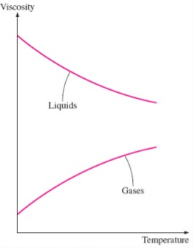
In a liquid, viscosity decreases with increase in temperature. In a gas, viscosity increases with increase in temperature.
3. Temperature:
It is the property that determines the degree of hotness or coldness or the level of heat intensity of a fluid. Temperature is measured by using temperature scales. There are 3 commonly used temperature scales. They are
- Celsius (or centigrade) scale
- Fahrenheit scale
- Kelvin scale (or absolute temperature scale)
Kelvin scale is widely used in engineering. This is because this scale is independent of properties of a substance.
The following graph clearly depicts the effect of temperature on fluids.
4. Pressure:
Pressure of a fluid is the force per unit area of the fluid. In other words, it is the ratio of force on a fluid to the area of the fluid held perpendicular to the direction of the force.
Pressure = force / area
Pressure is denoted by the letter ‘P’. Its unit is N/m2.
5. Specific Volume:
Specific volume is the volume of a fluid (V) occupied per unit mass (m). It is the reciprocal of density. Specific volume is denoted by the symbol ‘v’. Its unit is m3/kg.
Specific volume v= V/m (m3 / kg)
6. Specific Weight:
Specific weight is the weight possessed by unit volume of a fluid. It is denoted by ‘w’. Its unit is N/m3. Specific weight varies from place to place due to the change of acceleration due to gravity (g).
Specific weight w = Weight / volume (N/m3)
7. Specific Gravity:
Specific gravity is the ratio of specific weight of the given fluid to the specific weight of standard fluid. It is denoted by the letter ‘S’. It has no unit.
Specific gravity S= specific weight of given fluid /Specific weight of standard fluid
Specific gravity may also be defined as the ratio between density of the given fluid to the density of standard fluid.
S= ρ (given fluid) / ρ (standard fluid)
8. Surface tension
Surface tension is defined as the phenomenon in which the surface of liquid is in contact with another phase. The surface tension of water at 100°C is 0.059 N.m-1 and at 0°C it is 0.079 N.m-1.
T = F / L
CGS unit of surface tension is dyne/cm
SI unit of surface tension N/ m
II) Types of fluids:
The substance that has a tendency to flow is called as fluid. Generally, fluid is defined as a substance which is capable of spreading and changing its shape, according to is surroundings, without offering internal resistance.
In fluid mechanics, fluid is defined on the basis of its behaviour under the application of external forces. A solid, when subjected to a shearing force, deforms until the internal shear resistance equals the externally applied stress.
Within elastic limits or removal of the external force, the formation disappears and solid comes to its original shape. When a small shearing force is applied externally to the fluid it starts deforming and continues to do as long as applied force exists.
On removal of the external force, the fluid does not come to its original position. On the basis of this property, fluid can be defined as a substance which deforms continuously when subjected to external shearing force. This continuous deformation of fluid is known as flow.
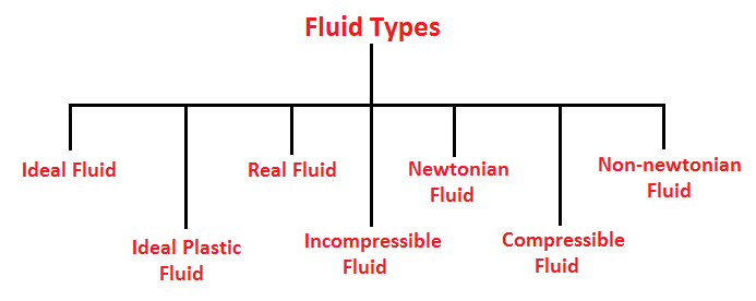
Based on how the property of viscosity of fluid changes in various fluids, they are divided into 5 types.
- Ideal fluid
- Real fluid
- Newtonian fluid
- Non-Newtonian fluid
- Ideal plastic fluid
- Incompressible fluid
- Compressible fluid
1) Ideal Fluid
The fluid, which is incompressible and has no viscosity or no friction, is known as an ideal fluid. Ideal fluid is only an imaginary fluid.
2) Real Fluid
A fluid, which possesses viscosity or friction, is known as real fluid.
3) Newtonian Fluid
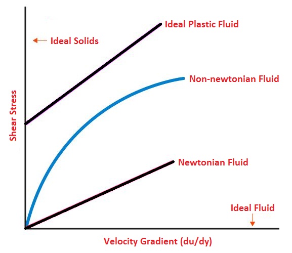
A real fluid, in which the shear stress is directly proportional to the rate of the shear strain, is known as a Newtonian fluid. Fluids obeying Newton’s law where the value of viscosity (μ) is constant are known as Newtonian fluids.
4) Non-Newtonian Fluid
A real fluid, in which the shear stress is not proportional to the rate of the shear strain, is known as a Non-Newtonian fluid. Fluids in which the value of viscosity (μ) is not constant are known as non-Newtonian fluids.
5) Ideal Plastic Fluid
A fluid, in which the shear stress is more than the yield value and shear stress is proportional to the rate of shear strain, is known as ideal plastic fluid.
6) Incompressible Fluid
A fluid, in which the density of the fluid does not change which changes to an external force or pressure, is known as an incompressible fluid.
7) Compressible Fluid
A fluid, in which the density of fluid changes while the change in external pressure or force, is known as compressible fluid.
Graphical Representation of Fluids
Some of the general categories of fluid flow problems are as follows;
1. Viscous and inviscid flow:
The fluid flow in which frictional effects become signification, are treated as viscous flow. When two fluid layers move relatively to each other, frictional force develops between them which is quantified by the fluid property ‘viscosity’. Boundary layer flows are the example viscous flow.
Neglecting the viscous terms in the governing equation, the flow can be treated as inviscid flow.
2. Internal and External flow:
The flow of an unbounded fluid over a surface is treated as ‘external flow’ and if the fluid is completely bounded by the surface, then it is called as ‘internal flow’.
For example, flow over a flat plate is considered as external flow and flow through a pipe/duct is internal flow. However, in special cases, if the duct is partially filled and there is free surface, then it is called as open channel flow. Internal flows are dominated by viscosity whereas the viscous effects are limited to boundary layers in the solid surface for external flows.
3. Compressible and Incompressible flow:
The flow is said to be ‘incompressible’ if the density remains nearly constant throughout. When the density variation during a flow is more than 5% then it is treated as ‘compressible’. This corresponds to a flow Mach number of 0.3 at room temperature.
Compressible fluid flow is defined as the flow in which the density is not constant which means the density of the fluid changes from point to point.
The density notation is ρ
ρ ≠ constant
Incompressible fluid flow is defined as the flow in which the density is constant which means the density of the fluid does not change from point to point.
ρ = constant
Gases are compressible fluid flow but whereas the liquid is incompressible fluid flow.
4. Laminar and Turbulent flow:
The highly ordered fluid motion characterized by smooth layers of fluid is called ‘Laminar Flow’, e.g. Flow of highly viscous fluids at low velocities.
The fluid motion that typically occurs at high velocities is characterized by velocity fluctuations are called as ‘turbulent.’ The flow that alternates between being laminar & turbulent is called ‘transitional’.
The dimensionless number i.e. Reynolds number is the key parameter that determines whether the flow is laminar or turbulent.
- If the Reynolds Number is less than 2000, the flow is called Laminar flow.
- Reynolds Number is more than 4000, the flow is called Turbulent flow.
- If the Reynolds Number is lies between 2000-4000, the flow may be laminar or turbulent.
5. Steady and Unsteady flow:
When there is no change in fluid property at point with time, then it implies as steady flow. However, the fluid property at a point can also vary with time which means the flow is unsteady/transient. The term ‘periodic’ refers to the kind of unsteady flows in which the flow oscillates about a steady mean.

Steady Flow

Unsteady flow
5. Natural and Forced flow:
In a forced flow, the fluid is forced to flow over a surface by external means such as a pump or a fan. In other case (natural flow), density difference is the driving factor of the fluid flow. Here, the buoyancy plays an important role. For example, a warmer fluid rises in a container due to density difference.
6. One/Two/Three dimensional flow: A flow field is best characterized by the velocity distribution, and thus can be treated as one/two/three dimensional flow if velocity varies in the respective directions.
One dimensional flow is that type of flow in which the flow parameter such as velocity is a function of time and one space co-ordinate only, say x.
u=f(x), v=0 and w=0
Where u,v and w are velocity component in x,y and z directions respectively.
Two-dimensional fluid flow is the type of flow in which velocity is a function of time and two rectangular space co-ordinate say x,y
u= f1(x,y,), v= f2(x,y,) and w= 0.
Three-dimensional fluid flow is the type of flow in which velocity is a function of time and three mutually perpendicular directions. The function of 3 space coordinates (x,y,z).
u= f1(x,y,z), v= f2(x,y,z) and w= f3(x,y,z).
7. Uniform and non-uniform flow:
This uniform fluid flow is defined as the type of flow in which the velocity at any given time does not change with respect to space (i.e length of direction of the flow).

Uniform flow
Whereas the Non-uniform flow is defined as,
This non-uniform fluid flow is defined as the type of flow in which the velocity at any given time changes with respect to space (i.e. length of the direction of the flow).

Non uniform flow
8. Rotational and irrotational Fluid flow:
The rotational fluid flow is defined as the type of fluid flow in which the fluid particles while flowing along streamline and also rotate about their own axis.
Whereas, The Ir-rotational fluid flow is defined as the type of fluid flow in which the fluid particles while flowing along streamline and do not rotate about their own axis.
III) Newton law of viscosity:
- Viscosity is the physical property that characterizes the flow resistance of simple fluids.
- Viscosity is the property of a fluid by virtue of its offers resistance to the movement of one layer of fluid over an adjacent layer.
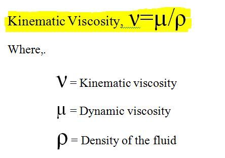
Kinematic viscosity/ momentum diffusivity:
- It is defined as the ratio of dynamic viscosity to the density of the fluid.
Newton’s Law of Viscosity:
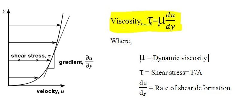
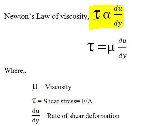
Newton’s viscosity law’s states that, the shear stress between adjacent fluid layers is proportional to the velocity gradients between the two layers.
The ratio of shear stress to shear rate is a constant, for a given temperature and pressure, and is defined as the viscosity or coefficient of viscosity.
Newtonian Fluid:
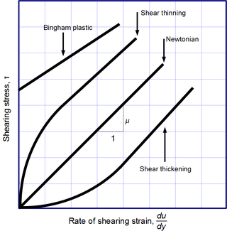
- A fluid, whose viscosity does not change with the rate of deformation or shear stain (V/Y), is called Newtonian fluid.
- A fluid which obeys Newton’s law of viscosity is termed as Newtonian fluid.
Non-Newtonian Fluid:
- A fluid, whose viscosity changes with the rate of deformation or shear stain (V/Y), is called Non-Newtonian fluid.
A fluid which does not obey Newton’s law of viscosity is termed as Non-Newtonian fluid.
IV) Pascal’s law:
Pascal's law states that when there is an increase in pressure at any point in a confined fluid, there is an equal increase at every other point in the container.
A container, as shown below, contains a fluid. There is an increase in pressure as the length of the column of liquid increases, due to the increased mass of the fluid above.
For example, in the figure below, P3 would be the highest value of the three pressure readings, because it has the highest level of fluid above it.
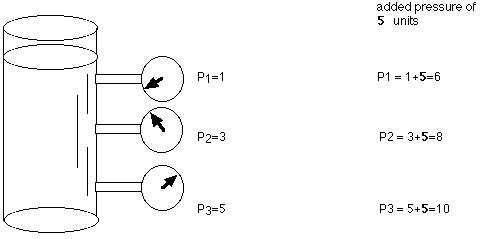
If the above container had an increase in overall pressure, that same added pressure would affect each of the gauges (and the liquid throughout) the same. For example P1, P2, P3 were originally 1, 3, 5 units of pressure, and 5 units of pressure were added to the system, the new readings would be 6, 8, and 10.
Applied to a more complex system below, such as a hydraulic car lift, Pascal's law allows forces to be multiplied. The cylinder on the left shows a cross-section area of 1 square inch, while the cylinder on the right shows a cross-section area of 10 square inches. The cylinder on the left has a weight (force) on 1 pound acting downward on the piston, which lowers the fluid 10 inches. As a result of this force, the piston on the right lifts a 10 pound weight a distance of 1 inch.
The 1 pound load on the 1 square inch area causes an increase in pressure on the fluid in the system. This pressure is distributed equally throughout and acts on every square inch of the 10 square inch area of the large piston. As a result, the larger piston lifts up a 10 pound weight. The larger the cross-section area of the second piston, the larger the mechanical advantage, and the more weight it lifts.
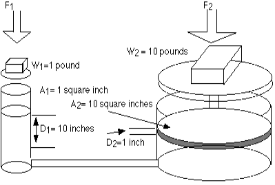
The formulas that relate to this are shown below:
P1 = P2 (since the pressures are equal throughout).
Since pressure equals force per unit area, then it follows that
F1/A1 = F2/A2
It can be shown by substitution that the values shown above are correct,
1 pound / 1 square inches = 10 pounds / 10 square inches
Because the volume of fluid pushed down on the left side equals the volume of fluid that is lifted up on the right side, the following formula is also true.
V1 = V2
By substitution,
A1 D1 = A2 D2
- A = cross sectional area
- D = the distance moved
Or
A1/A2= D2/D1
This system can be thought of as a simple machine (lever), since force is multiplied. The mechanical advantage can be found by rearranging terms in the above equation to
Mechanical Advantage (IMA) = D1/D2 = A2/A1
For the sample problem above, the IMA would be 10:1 (10 inches/ 1 inch or 10 square inches / 1 square inch).
V) Bernoulli equation for incompressible fluid:
The total mechanical energy of the moving fluid comprising the gravitational potential energy of elevation, the energy associated with the fluid pressure and the kinetic energy of the fluid motion, remains constant.
Bernoulli’s equation formula is a relation between pressure, kinetic energy, and gravitational potential energy of a fluid in a container.
The formula for Bernoulli’s principle is given as:
p + 1/ 2 ρ v2 + ρgh =constant
Where,
- p is the pressure exerted by the fluid
- v is the velocity of the fluid
- ρ is the density of the fluid
- h is the height of the container
Bernoulli’s equation gives great insight into the balance between pressure, velocity, and elevation.
Bernoulli’s Equation Derivation
Consider a pipe with varying diameter and height through which an incompressible fluid is flowing. The relationship between the areas of cross-sections A, the flow speed v, height from the ground y, and pressure p at two different points 1 and 2 is given in the figure below.
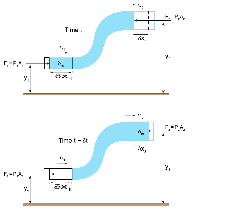
Assumptions:
- The density of the incompressible fluid remains constant at both points.
- The energy of the fluid is conserved as there are no viscous forces in the fluid.
Therefore, the work done on the fluid is given as:
DW = F1dx1 – F2dx2
DW = p1A1dx1 – p2A2dx2
DW = p1dV – p2dV = (p1 – p2)dV
We know that the work done on the fluid was due to conservation of gravitational force and change in kinetic energy. The change in kinetic energy of the fluid is given as:
DK=1/2m2v22−1/ 2m1v21=1 / 2ρdV (v22−v21)
The change in potential energy is given as:
DU = mgy2 – mgy1 = ρdVg (y2 – y1)
Therefore, the energy equation is given as:
DW = dK + dU
(p1 – p2) dV = 1/ 2ρdV (v22−v21) + ρdVg (y2 – y1)
(p1 – p2) = 1/2ρ (v22−v21) + ρ g(y2 – y1)
Rearranging the above equation, we get
p1+ (1/2)ρv21+ρgy1=p2+1/2ρv22+ρgy2
Or
p + (1/ 2) ρ v2 + ρgh =constant
This is Bernoulli’s equation.
Thus, we can state that Bernoulli’s equation state that the Pressure (P), potential energy (ρgy) per unit volume and the kinetic energy (ρv2/2) per unit volume will remain constant.
Assumptions made in the derivation of Bernoulli's equation
(i).The fluid is ideal, i.e., Viscosity is zero.
(ii) The flow is steady
(iii) The flow is incompressible.
(iv) The flow is irrotational.
VI) Working principle of:
i) Hydraulic machine:
The controlled movement of parts or a controlled application of force is a common requirement in the industries. These operations are performed mainly by using electrical machines or diesel, petrol and steam engines as a prime mover. These prime movers can provide various movements to the objects by using some mechanical attachments like screw jack, lever, rack, and pinions etc. However, these are not the only prime movers. The enclosed fluids (liquids and gases) can also be used as prime movers to provide controlled motion and force to the objects or substances. The specially designed enclosed fluid systems can provide both linear as well as rotary motion. The high magnitude controlled force can also be applied by using these systems. This kind of enclosed fluid based systems using pressurized incompressible liquids as transmission media are called as hydraulic systems. The hydraulic system works on the principle of Pascal’s law which says that the pressure in an enclosed fluid is uniform in all the directions. The Pascal’s law is illustrated in the figure.
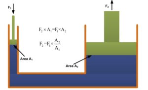
The force given by fluid is given by the multiplication of pressure and area of cross-section. As the pressure is same in all the direction, the smaller piston feels a smaller force and a large piston feels a large force. Therefore, a large force can be generated with smaller force input by using hydraulic systems.
Working:
The hydraulic systems consists a number of parts for its proper functioning. The schematic of a simple hydraulic system is shown. It consists of:
• a movable piston connected to the output shaft in an enclosed cylinder
• storage tank
• filter
• electric pump
• pressure regulator
• control valve
• leak proof closed loop piping.
- The output shaft transfers the motion or force however, all other parts help to control the system. The storage/fluid tank is a reservoir for the liquid used as a transmission media.
- The liquid used is generally high-density incompressible oil. It is filtered to remove dust or any other unwanted particles and then pumped by the hydraulic pump.
The capacity of the pump depends on the hydraulic system design. These pumps generally deliver constant volume in each revolution of the pump shaft. Therefore, the fluid pressure can increase indefinitely at the dead end of the piston until the system fails. - The pressure regulator is used to avoid such circumstances which redirect the excess fluid back to the storage tank. The movement of piston is controlled by changing liquid flow from port A and port B.
The cylinder movement is controlled by using control valve which directs the fluid flow. The fluid pressure line is connected to the port B to raise the piston and it is connected to port A to lower down the piston. The valve can also stop the fluid flow in any of the port. The leak-proof piping is also important due to safety, environmental hazards and economical aspects.
Hydraulic Pumps:
The combined pumping and driving motor unit is known as a hydraulic pump. They can be of two types:
1. Centrifugal pumps:
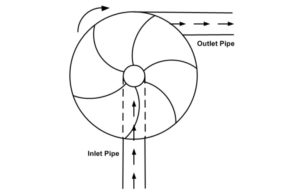
Centrifugal pump uses rotational kinetic energy to deliver the fluid. The rotational energy typically comes from an engine or electric motor.
2. Reciprocating pumps:
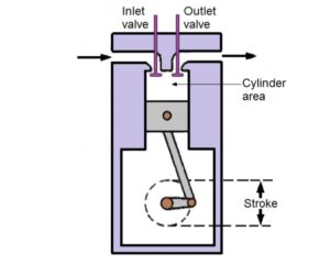
The reciprocating pump is a positive plunger pump. It is also known as positive displacement pump or piston pump. It is often used where relatively small quantity is to be handled and the delivery pressure is quite large. The construction of these pumps is similar to the four-stroke engine.
Applications of hydraulic systems:
The hydraulic systems are mainly used for precise control of larger forces. The main applications of the hydraulic system can be classified into five categories:
1. Industrial: Plastic processing machinery, steel making and primary metal extraction applications, automated production lines, machine tool industries, paper industries, loaders, crushes, textile machinery, R & D equipment and robotic systems etc.
2. Mobile hydraulics: Tractors, irrigation system, earthmoving equipment, material handling equipment, commercial vehicles, tunnel boring equipment, rail equipment, building, and construction machinery and drilling rigs etc.
3. Automobiles: It is used in the systems like breaks, shock absorbers, steering system, wind shield, lift, and cleaning etc.
4. Marine applications: It mostly covers ocean-going vessels, fishing boats, and navel equipment.
5. Aerospace equipment: There are equipment and systems used for rudder control, landing gear, breaks, flight control and transmission etc. which are used in airplanes, rockets, and spaceships.
Advantages and disadvantages of Hydraulic Systems:
Advantages:
• The hydraulic system uses incompressible fluid which results in higher efficiency.
• It delivers consistent power output which is difficult in pneumatic or mechanical drive systems.
• Hydraulic systems employ high-density incompressible fluid. The possibility of leakage is less in a hydraulic system as compared to that in a pneumatic system. The maintenance cost is less.
• These systems perform well in hot environmental conditions.
Disadvantages:
• The material of storage tank, piping, cylinder, and piston can be corroded with the hydraulic fluid. Therefore one must be careful while selecting materials and hydraulic fluid.
• The structural weight and size of the system is more which makes it unsuitable for the smaller instruments.
• The small impurities in the hydraulic fluid can permanently damage the complete system, therefore one should be careful and suitable filter must be installed.
• The leakage of hydraulic fluid is also a critical issue and suitable prevention method and seals must be adopted.
• The hydraulic fluids, if not disposed of properly, can be harmful to the environment.
Ii) Pumps:
A pump is a device that is used for lifting the liquid from ground sources to the upper top surface or from one place to another place. Pumps are operated by the mechanism that is rotary, reciprocating and it consumes energy while performing mechanical work which is moving fluid from one place to another.This can be operated by many energy resources which include manual operation, electricity, engine, wind power and many more, day to day life to industrial applications.
Types of Pumps:
A pump can broadly be classified into two categories, and those are:
- Positive Displacement Pump
- Dynamic Pump
Also, there are two types of Positive Displacement Pump, and those are:
- Rotary Pump
- Single Rotor Pump (For example, Piston Pump, Vane Pump, Screw Pump)
- Multiple Rotor Pump (For example, Gear pump, Lube pump)
- Reciprocating Pump
- Diaphragm Pump (For example, Fluid Operated Pump, Mechanically Operated Pump)
- Piston Plunger Type Pump
And again Dynamic Pumps can be classified into two types:
- Centrifugal Pump
- Axial Pump
Reciprocating Pump:
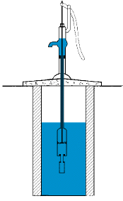
A reciprocating pump is a hydraulic machine which converts the mechanical energy into hydraulic energy. Here a certain volume of liquid is collected in the enclosed volume and is discharged using pressure to the required application.
Reciprocating pumps are more suitable for low volumes of flow at high pressures. The reciprocating pump having two types:
- Single-acting reciprocating pump
- Double acting reciprocating pump
Parts of Reciprocating Pump:
These are the main parts of a Reciprocating Pump:
- Suction Pipe
- Suction Valve
- Delivery Pipe
- Delivery Valve
- Cylinder
- Piston and Piston Rod
- Crank and Connecting Rod
- Strainer
- Air Vessel
Suction Pipe:
It is used to suck the water from the water reservoir to the cylinder. It connects the inlet of the pump with the water tank.
Suction Valve:
The suction valve is a non-return valve which means the only one-directional flow is possible in this type of valve. This is placed between the suction pipe inlet and the cylinder. During suction of liquid, it is opened and during discharge, it is closed.
Delivery Pipe:
It is a pipe that is used to deliver the water from the cylinder to the desired location. It connects the outlet of the pump to the tank where the water is to be delivered.
Delivery Valve:
Delivery valve also non-return valve placed between the cylinder and delivery pipe outlet It is in a closed position during suction and opened position during the discharging of liquid.
Cylinder:
A hollow cylinder made of steel alloy or cast iron. An arrangement of piston and piston rod is inside this cylinder.
Piston and Piston Rod:
A piston is a solid type cylinder part which moves backward and forwards inside the hollow cylinder, to perform suction and delivery of liquid. Piston rod helps the piston to its linear motion.
Crank and Connecting Rod:
Crank is a solid circular disc which is connected to the power source like motor, engine, etc, for its rotation. Connecting rod connects the crank to the piston, as a result, the rotational motion of the crank gets converted into linear motion of the piston.
Strainer:
A strainer is provided at the end of the suction pipe to prevent the entrance of solids from a water source into the cylinder.
Air Vessel:
Air vessels are connected to both suction and delivery pipes to eliminate the frictional head and to give a uniform discharge rate.
Centrifugal Pump:
The hydraulic machine which converts the mechanical energy into hydraulic energy is called Pumps. The hydraulic energy is in the form of pressure energy if the mechanical energy is converted into pressure energy by means of a centrifugal force acting on the fluid, the hydraulic machine is called a Centrifugal Pump.
Main Parts of Centrifugal Pump:
- Impeller
- Casing
- Suction pipe with a foot valve
- Strainer and
- Delivery pipe
Impeller:
An impeller is a rotating component of a centrifugal pump which transfers energy from the motor that drives the pump to the fluid being pumped by accelerating the fluid outwards from the center of rotation.
Casing: The Casing that receives the fluid being pumped by the impeller, slowing down the fluid’s rate of flow.A volute is a curved funnel that increases in area as it approaches the discharge port.
Suction pipe with a foot valve and Strainer:
A pipe whose one end is connected to the inlet of the pump and another end dips into the water in a sump is known as a suction pipe. A foot valve is found at the end of a pipeline in a suction lift application. They function as a check valve, but they also have a strainer affixed to their open end.
Delivery pipe:
A pipe whose one end is connected to the outlet of the pump and other ends delivers the water at a required height is known as a Delivery pipe.
Advantages of Pump:
These are some advantages of Pump:
- As there is no drive seal so there is no leakage in the pump.
- There are very less frictional losses.
- The construction of the pump is Simple.
- Almost no noise.
- Minimum wear as compared to others.
Disadvantages of Pump:
These are some disadvantages of Pump:
- Produce cavitation.
- Corrosion.
- Cannot be able to work at high speed.
Applications of Pump:
The main applications of the pump are:
- As we already discussed Pumping Water from one place to another place.
- Aquarium and pond filtering
- This is also used for Water cooling and fuel injection in automobiles
- Pumping oil or gas and operating cooling towers in the energy industry.
- Uses in waste-water recycling, pulp, and paper, chemical industry, etc.
Iii) Turbine:
A turbine is a machine that transforms rotational energy from a fluid that is picked up by a rotor system into usable work or energy. Turbines achieve this either through mechanical gearing or electromagnetic induction to produce electricity. Types of turbines include steam turbines, wind turbines, gas turbines or water turbines. Mechanical uses of turbine power go back to ancient Greece. The first wind wheels relied upon gearing and shafts to power machinery. Windmills and water wheels are forms of turbines too and might drive a millstone to grind grain, among other purposes.
Thermal steam turbines driven by burning oil or coal or the use of nuclear power are still among the most common methods of producing electricity. Green electricity applications include wind turbines and water turbines used in applications for wind power and tidal power
.
A turbine is a mechanical device which extracts energy from a moving fluid and converts it into useful work. The turbines are basically used to produce electricity.
Main Parts of a Turbine
The main parts of a turbine are
- Nozzle: It guides the steam to flow in designed direction and velocity.
- Runner: it is the rotating part of the turbine and blades are attached to the runner.
- Blades: It is that part of the turbine on which the fast moving fluid strikes and rotates the runner.
- Casing: It is the outer air tight covering of the turbine which contains the runner and blades. It protects the internal parts of the turbine.
Working Principle of a Turbine
- A fast moving fluid (it may be water, gas, steam or wind) is made to strike on the blades of the turbine.
- As the fluid strikes the blades, it rotates the runner. Here the energy of the moving fluid is converted into rotational energy.
- A generator is coupled with the shaft of the turbine. With the rotation of the runner of the turbine, the shaft of the generator also rotates. The generator converts the mechanical energy of the runner into electrical energy.
Types of Turbine
 Basically turbines are classified into four types
- Water turbine
- Steam turbine
- Gas turbine
- Wind turbine
1) Water Turbine
A turbine that extracts energy from moving water and converts it into electrical energy, is called water turbine or hydraulic turbine.
Types of Hydraulic Turbine
The hydraulic turbines are classified on the following basis
1. According to the Type of Energy Available at Inlet.
(i). Impulse Turbine:
If the energy available at the inlet of the turbine is only kinetic energy, the turbine is known as impulse turbine.
(ii). Reaction Turbine:
If the energy available at the inlet of the turbine is kinetic energy as well as pressure energy, the turbine is known as reaction turbine.
2. According to the Direction of Flow
(i). Tangential Flow Turbine:
If the water flows along the tangent of the runner, the Turbine is known as tangential flow turbine. For Example: Pelton turbine.
(ii). Radial Flow Turbine:
If the water flows in the radial direction through the runner, the turbine is called radial flow turbine.
(iii). Axial Flow Turbine:
If the water flows through the runner along the direction parallel to the axis of rotation of the runner the turbine is called axial flow turbine.
(iv). Mixed Flow Turbine:
If the water flows through the runner in the radial direction but leaves in the direction parallel to the axis of rotation of the runner, the turbine is called mixed flow turbine. For example: Kaplan Turbine
3. According to the Head at the Inlet of Turbine
(i). High Head Turbine:
The net head varies in this turbine is from 150 m to 2000 m or even more. It requires small quantity of water. E.g.: pelton turbine.
(ii). Medium Head Turbine:
In this turbine, the net head varies from 30 m to 150 m. It requires moderate quantity of water. Eg: Francis turbine.
(iii). Low Head Turbine:
In low head turbines, the net head is less than 30 m. It requires large quantity of water. Eg: Kaplan turbine.
4. According to the Specific Speed of the Turbine
(i). Low Specific Speed Turbine:
It has specific speed less than 50. Eg: pelton turbine.
(ii). Medium Specific Speed Turbine:
The specific speed varies from 50 to 250. Eg Francis turbine.
(iii). High Specific Speed Turbine:
The specific speed is more than 250. Eg: Kaplan turbine.
Steam Turbine
A Turbine which extracts energy form the moving steam and converts it into electrical energy is called steam turbine.
Types of Steam Turbine
1. According to the Mode of Steam Action
(i). Impulse Turbine:
If the steam available at the inlet has only kinetic energy, the turbine is called impulse turbine.
(ii). Reaction Turbine:
If the steam available at the inlet has kinetic energy as well pressure energy, the turbine is called reaction turbine.
2. According to the Direction of Steam Flow
(i). Axial Flow Turbine:
If the steam flows through the runner in the direction parallel to the axis of rotation of the runner, the turbine is called axial flow turbine
(ii). Radial Flow Turbine:
If the steam flows through the runner in the radial direction, the turbine is called radial flow turbine.
3. According to the Exhaust Condition of Steam
(i). Condensing Turbine:
A turbine in which the steam is condensed, when it comes out of the turbine is called condensing turbine. It produces large output with single unit.
(ii). Non-Condensing Turbine:
In non-condensing turbine, the exhaust steam leaves the turbine at atmospheric pressure or low pressure. There is no condensation of steam takes place in this turbine.
4. According to the Pressure of Steam
(i). High Pressure Turbine
(ii). Medium Pressure Turbine
(iii). Low Pressure Turbine
5. According to the Number of Stages
(i) Single Stage Steam Turbine:
In single stage steam turbine, the steam after leaving the nozzle, impinges on one end of the blade, glides over the inner surface, leaves the blades and exhaust into the condenser.
(ii) Multi Stage Steam Turbine:
In multi stages turbine, sometimes the steam after leaving the moving blade is again made to flow through a fixed blade ring and again impinges on second moving blade. Here the fixed blade ring is used to make the steam to flow at a desired angle. In multistage steam turbine more than one set of rotor blades are used.
Gas Turbine
A turbine which extracts energy from the hot moving gas and converts it into electricity, is called gas turbine.
Types of Gas Turbine
1. According to the Path of Working Substance
(i). Closed Cycle Gas Turbine:
In closed cycle gas turbine the, the air (gas) is continuously circulates within the turbine.
(ii). Open Cycle Gas Turbine:
In this type of turbine, the air is not circulated continuously within the turbine. The air after flowing over the blades of the turbine exhausted in the atmosphere.
(iii). Semi-Closed Gas Turbine:
As the name indicates, the semi-closed gas turbine is the combination of both the turbines, one working on the open cycle and the other on the closed cycle.
2. According to the Process of Heat Absorption
(i). Constant Pressure Gas Turbine:
A turbine in which the air is heated at constant pressure in the combustion chamber is called constant pressure gas turbine.
(ii). Constant Volume Gas Turbine:
A turbine in which the air is heated at constant volume in the combustion chamber is called constant volume gas turbine.
Wind Turbine
A turbine which extracts energy from the fast moving wind and converts it into electricity, is called wind turbine
Types of Wind Turbine
The wind turbines are of two types
(i). Horizontal Axis Wind Turbine (HAWT):
A wind turbine in which the shaft of the turbine is horizontal to the ground is called horizontal axis wind turbine. In other words if the axis of rotation of the turbine blades are horizontal to the ground than it is known as horizontal axis wind turbine.
(ii). Vertical Axis Wind Turbine (VAWT):
A wind turbine in which the shaft of the turbine is vertical to the ground is called vertical axis wind turbine. In other words, if the axis of rotation of the turbine blades are vertical to the ground than the turbine is known as vertical axis wind turbine.
Iv) Reciprocating pumps:
Reciprocating pump is a device which converts the mechanical energy into hydraulic energy by sucking the liquid into a cylinder. In this pump, a piston is reciprocating, which uses thrust on the liquid and increases its hydraulic energy. Reciprocating pump is also known a called a positive displacement pump. Because it discharges a definite quantity of liquid. It is often used where a small quantity of liquid is to handled and where delivery pressure is quite large.
Parts of Reciprocating Pump The following are the main parts of the reciprocating pump.
- Cylinder
- Suction Pipe
- Delivery Pipe
- Suction valve
- Delivery valve
- Air vessels
1) Cylinder
A cylinder, in which piston is moving to and fro. The moment of the piston obtains by a connecting rod, which connects the piston and crank.
2) Suction Pipe
In which the source of water connects the cylinder together. The suction pipe allows the water to flow in the cylinder.
3) Delivery Pipe
After the process, the source of water leaves the cylinder and discharge through the delivery pipe.
4) Suction Valve
In this valve, the flow of water enters from the suction pipe into the cylinder.
5) Delivery Valve
In this valve, the flow of water discharge from the cylinder into the delivery pipe.
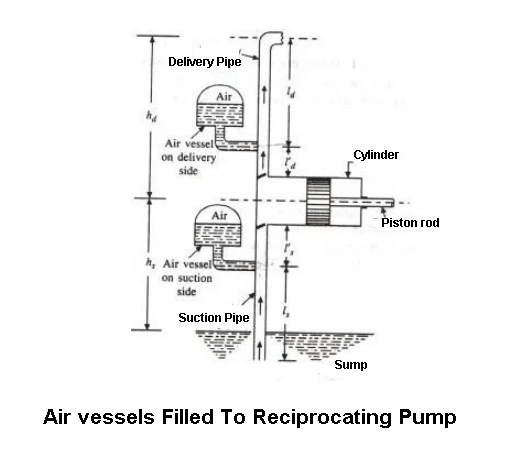
6) Air Vessels
It is a closed chamber made up cast iron. Having to two ends one ends is open at its base through which the water flows into the vessel cylinder. The air vessels fitted to the suction pipe and delivery pipe of this pump to get a uniform discharge.
Functions of Air Vessels
- The air vessels use to get the continuous flow of water at a uniform rate.
- To reduce the amount of work in overcoming the frictional resistance in the suction pipe and delivery pipe.
- To run the pump at high speed with separation.
Types of Reciprocating Pump
The following are the types of reciprocating pump according to the source of work and mechanism.
- Simple hand-operated reciprocating pump
- Power-operated deep well reciprocating pump
- Single-acting reciprocating pump
- Double-acting reciprocating pump
- Triple-acting reciprocating pump
- Pump with air vessels
- Pump without air vessels
Working Principle of Reciprocating Pump
Following are the two different working principles:
- Single-acting reciprocating pump and
- A double-acting reciprocating pump.
1. Single Acting Reciprocating Pump
In this pump, A cylinder, in which a piston moves forward and backward. The piston is reciprocating by means of the connecting rod. The connecting rod connects the piston and the rotating crank. The crank is rotating by means of an electric motor.
The suction and delivery pipes with suction and delivery valve are arranged to the cylinder.
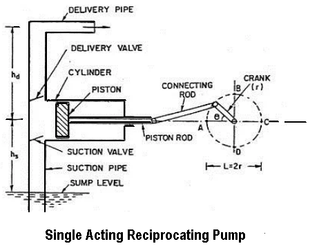
- The suction valve allows the water to the cylinder and
- The delivery valve leaves the water from the cylinder.
As the crank rotates, during the first stroke of the piston (called suction stroke), the water enters into the cylinder. In a suction stroke, the crank is rotating from A to C (from 0° to 180°) the piston is moving towards the right side of the cylinder. Due to this, the vacuum creates in the cylinder. This vacuum causes the suction valve to open and the water enters the cylinder.
In the next stroke called delivery stroke, the water leaves the cylinder. In the delivery stroke, the crank is rotating from C to A (from 180° to 360°) the piston is moving to the left side of the cylinder. Due to this, the pressure of the liquid increases inside the cylinder. This pressure causes the suction valve to close and delivery valve to open. Then the water is forced into the delivery pipe and raised to a required height.
2. Double Acting Reciprocating Pump
In this, the water is acting on both sides of the piston as shown in the figure.
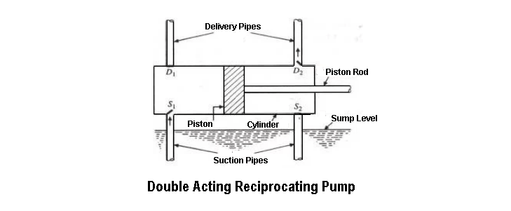
Thus two suction pipes and two delivery pipes are required for a double-acting pump. When there is a suction stroke on one side of the piston, at the same time there is a delivery stroke on the other side of the piston.
Hence for one complete revolution of the crank, there is two delivery stroke and the water is delivered to the pipes by the pump during these two delivery strokes.