Unit 5
Electrostatics in vacuum
Suppose, a system of charges having charges as q1, q2, q3……. Up to qn. We can easily find out the net charge by adding charges algebraically.
Net electric field and net force can be obtained by using the principle of superposition. The continuous charge distribution system is a system in which the charge is uniformly distributed over the conductor. In continuous charge system, infinite numbers of charges are closely packed and have minor space between them.
Unlikely from the discrete charge system, the continuous charge distribution is uninterrupted and continuous in the conductor. There are three types of the continuous charge distribution system. Types of continuous charged distributions:
1. Linear Charge Distribution
2. Surface Charge Distribution
3. Volume charge distribution
Linear Charge Distribution:
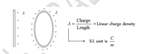
When the distribution of charge is uniformly along the line then it is called Linear Charge Distribution. e.g. Line making the circumference of a circle, straight line, etc. Here we define a new physical quantity called the linear charge density, It is denoted by symbol ‘λ’ and is given by---
λ = dq / dl.
And Such that total charge on the distribution is
q =∫ λ dl
It is measured in Cm-1. Let us take a small element having length dl of the line. The small amount of charge on this element is dq= λ. Dl
Surface Charge Distribution:
When charge is distributed uniformly over some area it is called surface charge distribution.
For example, a charged thin sheet. The surface charge density σ of a wire is given as where Δs is a small area element of a charged sheet and ΔQ is the charge contained in that area element. The unit for σ is C/m2.
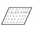
Also, dq =σ ds and q =∫ σ ds
Volume Charge Density:
Is defined as continuous charge distribution over a volume.
For example, a metal sphere or cylinder etc. The volume charge density or simply called charge density ρ is given as

Where ΔV is a small volume element of a charged sphere on macroscopic scale and ΔQ is the charge contained in that volume element. The unit for ρ is C/m3 or coulomb per cubic metre
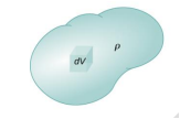
Also, dq = ρ dv and q = ∫ ρ dv
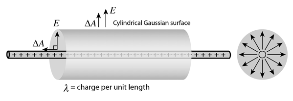
The electric field of an infinite line charge with a uniform linear charge density can be obtained by a using Gauss' law. Considering a Gaussian surface in the form of a cylinder at radius r, the electric field has the same magnitude at every point of the cylinder and is directed outward. The electric flux is then just the electric field times the area of the cylinder.

|
|
Electric Field:
Sheet of Charge
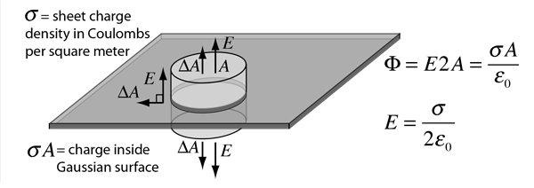
For an infinite sheet of charge, the electric field will be perpendicular to the surface. Therefore, only the ends of a cylindrical Gaussian surface will contribute to the electric flux. In this case a cylindrical Gaussian surface perpendicular to the charge sheet is used. The resulting field is half that of a conductor at equilibrium with this surface charge density.
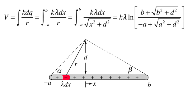
The potential of a line of charge can be found by superposing the point charge potentials of infinitesimal charge elements. It is an example of a continuous charge distribution.
Potential: Charged Conducting Sphere
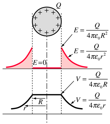
The use of Gauss' law to examine the electric field of a charged sphere shows that the electric field environment outside the sphere is identical to that of a point charge. Therefore, the potential is the same as that of a point charge:

The electric field inside a conducting sphere is zero, so the potential remains constant at the value it reaches at the surface:

Electric displacement, denoted by D, is the charge per unit area that would be displaced across a layer of conductor placed across an electric field. It is also known as electric flux density.
Electric displacement is used in the dielectric material to find the response of the materials on the application of an electric field E. In Maxwell’s equation, it appears as a vector field.
The SI unit of electric displacement is Coulomb per meter square (C m-2).

Where,
- ϵ0: Vacuum permittivity
- P: Polarization density
- E: Electric field
- D: Electric displacement field
It was found that if electric field E is applied on the dielectric material, the bound charges inside the material responds to the electric field such that the distribution of positive changes take place in the direction of the electric field while the distribution of negative charges takes place in the opposite direction of the electric field. Before the application of the electric field, the material is electrically neutral and there is a formation of electric dipoles.
A dielectric may be made up of polar or non-polar molecules. But the net effect of an external field is almost the same, i.e., the external field will compel the molecules to align their dipole moments along its own direction.
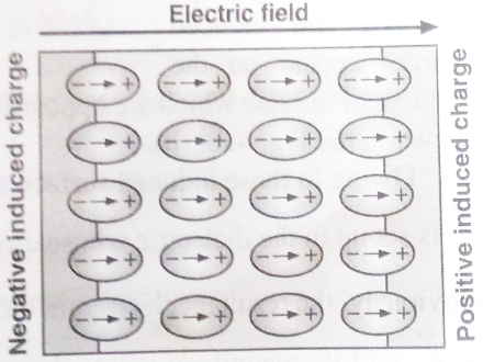
Let us consider a dielectric slab in an electric field which is acting in the direction shown in the figure. The arrangement of charges within the molecules of the dielectric in the electric field is as shown in the figure. The positive charges move in the direction of the field and the negative charges in the opposite direction. In other words, the electric dipoles align themselves with the direction of the field. In this state, the entire dielectric and its molecules are said to be polarised.
The alignment of the dipole moments of the permanent or induced dipoles with the direction of the applied electric field is called polarisation.
Within the two extremely thin surface layers indicated by shaded regions, there is an excess negative charge in one layer and an excess equal positive charge in the other layer.
The induced charges on the surfaces of the dielectric are due to these layers. These charges are not free but each is bound to a molecule lying in or near the surface. That is why these charges are called bound charges or fictitious charges. Within the remaining dielectric, the net charge per unit volume remains zero. Thus, although the dielectric is polarized, yet as a whole, it remains electrically neutral.
Polar Molecules
A polar molecule is one in which the ‘centres of gravity’ of the positive charges (i.e., protons) and negative charges (i.e., electrons) do not coincide. Such molecules are called permanent electric dipoles as these have permanent dipole moments. Some common polar molecules are HCl, H2O, N2O, NH3, H2S, C2H5OH, SO2.
In a molecule of HCl, there is an excess positive charge on the H-ion and an equal negative charge on the Cl-ion. The molecule, therefore, has a dipole moment at every instant and is a polar molecule. Another interesting example of polar molecules is H2O.
In the water molecule, two O-H bonds are not placed opposite to each other (unlike the CO2 molecule) but are inclined at an angle of about 105°. The hydrogen ion forms a dipole moment with each of the oxygen ion,
(i) In the absence of an electric field, the electric dipole moments of these polar molecules point in random directions [Fig. (b)] and cancel each other. Therefore, even though each molecule has a dipole moment, the average moment per unit volume is zero.
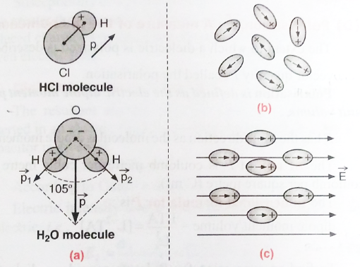
(ii) On the application of an electric field, the dipole moments of these molecules align themselves parallel, to the direction of the electric field as shown in figure (c). But this alignment is incomplete due to the thermal vibrations of the molecules. It is obvious that the alignment of the molecules with the applied field increases if:
- The electric intensity of the field is increased.
- Temperature is decreased.
It should be noted that increased electric intensity may also increase the dipole moment. It is due to the reason that with increased electric intensity, the distance between the centres of gravity of the positive and negative charges increases which results in an increase in the dipole moment.
A non-polar molecule is one in which the centres of gravity of positive charges (i.e., protons) and negative charges (i.e., electrons) coincide. These molecules, thus, do not have any permanent dipole moment.
Some common examples of non-polar molecules are CO2, CCl4, oxygen (O2), nitrogen (N2), hydrogen (H2), methane (CH4) and ethane (C2H6).
In a molecule of CO2, the oxygen ions are symmetrically placed with respect to the carbon ion, hence the dipole moment is zero
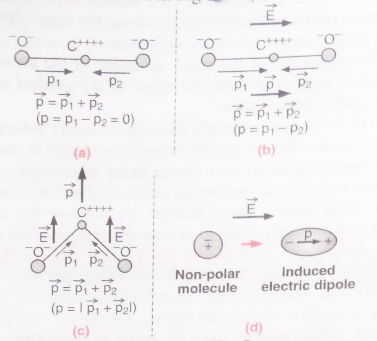
In CCl4, the external electric field changes the orientation of the C-Cl bond and thus produces induced dipole moment.
Thus, in general, when a non-polar molecule is placed in an electric field, the centres of positive and negative charges get displaced and the molecule is then said to have been polarized as shown in fig. (d). Such a molecule is then called the induced electric dipole and its electric dipole moment is called the induced electric dipole moment. As soon as the electric field is removed, the induced electric dipole moment disappears.
One of the values of calculating the scalar electric potential (voltage) is that the electric field can be calculated from it. The component of electric field in any direction is the negative of rate of change of the potential in that direction.
If the differential voltage change is calculated along a direction ds, then it is seen to be equal to the electric field component in that direction times the distance ds.

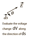
The electric field can then be expressed as

This is called a partial derivative. |
For rectangular coordinates, the components of the electric field are
 |
|
Express as a gradient.
The expression of electric field in terms of voltage can be expressed in the vector form
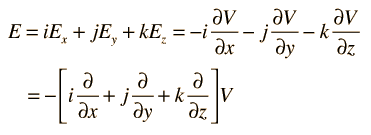
This collection of partial derivatives is called the gradient, and is represented by the symbol ∇. The electric field can then be written

Expressions of the gradient in other coordinate systems are often convenient for taking advantage of the symmetry of a given physical problem.
One approach to continuous charge distributions is to define electric flux and make use of Gauss' law to relate the electric field at a surface to the total charge enclosed within the surface. This involves integration of the flux over the surface.
Another approach is to relate derivatives of the electric field to the charge density. This approach can be considered to arise from one of Maxwell's equations and involves the vector calculus operation called the divergence. The divergence of the electric field at a point in space is equal to the charge density divided by the permittivity of space.

In a charge-free region of space where r = 0, we can say

While these relationships could be used to calculate the electric field produced by a given charge distribution, the fact that E is a vector quantity increases the complexity of that calculation. It is often more practical to convert this relationship into one which relates the scalar electric potential to the charge density. This gives Poisson's equation and Laplace’s equation.
The curl of a vector field E = E (x, y, z) is defined, in terms of the del operators ∇, like a cross product

The proof of curl-free nature of static electric fields can be given by first showing that Coulomb field of a static charge is curl-free, and then making use of the superposition principle along with the fact that the curl of a sum must be the sum of curls — like differentiation, “taking curl” is a linear operation
t ∇ × E = 0
with the Coulomb field of a point charge Q located at the origin.
Stokes Theorem (also known as Generalized Stoke’s Theorem) is a declaration about the integration of differential forms on manifolds, which both generalizes and simplifies several theorems from vector calculus. As per this theorem, a line integral is related to a surface integral of vector fields.
The Stoke’s theorem states that “the surface integral of the curl of a function over a surface bounded by a closed surface is equal to the line integral of the particular vector function around that surface.”
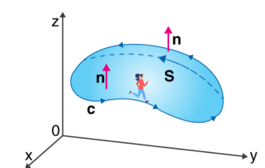
∮CF⃗.dr→=∬S (▽×F⃗ ).dS→
Where,
C = A closed curve.
S = Any surface bounded by C.
F = A vector field whose components have continuous derivatives in an open region of R3 containing S.
This classical declaration, along with the classical divergence theorem, fundamental theorem of calculus, and Green’s theorem are exceptional cases of the general formulation specified above.
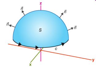
If you walk in the positive direction around C with your head pointing in the direction of n, the surface will always be on your left.
S is an oriented smooth surface bounded by a simple, closed smooth-boundary curve C with positive orientation.
According to Gauss’s theorem the net-outward normal electric flux through any closed surface of any shape is equivalent to 1/ε0 times the total amount of charge contained within that surface
Proof of Gauss’s Theorem Statement:
- Let the charge be = q
- Let us construct the Gaussian sphere of radius = r
Now, Consider, A surface or area ds having ds (vector)
Normal having the flux at ds:
Flux at ds:
d e = E (vector) d s (vector) cos θ
But, θ = 0
Therefore, Total flux:
C = f d Φ
E 4 π r2
Therefore,
σ = 1 / 4πɛo q / r2 × 4π r2
σ = q / ɛo
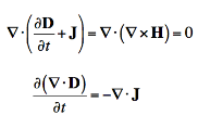
The Continuity Equation If we do some simple mathematical tricks to Maxwell's Equations, we can derive some new equations. On this page, we'll look at the continuity equation, which can be derived from Gauss' Law and Ampere's Law. To start, I'll write out a vector identity that is always true, which states that the divergence of the curl of any vector field is always zero:
If we apply the divergence to both sides of Ampere's Law, then we obtain:
If we apply Gauss' Law to rewrite the divergence of the Electric Flux Density (D), we have derived the continuity equation:
But what does it mean? The left side of the equation is the divergence of the Electric Current Density (J). This is a measure of whether current is flowing into a volume (i.e. the divergence of J is positive if more current leaves the volume than enters). Recall that current is the flow of electric charge. So, if the divergence of J is positive, then more charge is exiting than entering the specified volume. If charge is exiting, then the amount of charge within the volume must be decreasing. This is exactly what the right side is a measure of - how much electric charge is accumulating or leaving in a volume. Hence, the continuity equation is about continuity - if there is a net electric current is flowing out of a region, then the charge in that region must be decreasing. If there is more electric current flowing into a given volume than exiting, than the amount of electric charge must be increasing |
Maxwell's equations represent one of the most elegant and concise ways to state the fundamentals of electricity and magnetism. From them one can develop most of the working relationships in the field. Because of their concise statement, they embody a high level of mathematical sophistication and are therefore not generally introduced in an introductory treatment of the subject, except perhaps as summary relationships.
These basic equations of electricity and magnetism can be used as a starting point for advanced courses, but are usually first encountered as unifying equations after the study of electrical and magnetic phenomena.
Integral form in the absence of magnetic or polarizable media:
I. Gauss' law for electricity |  |
II. Gauss' law for magnetism |  |
III. Faraday's law of induction |  |
IV. Ampere's law |  |
Maxwell equation for non-conducting medium are

The energy in any part of the electromagnetic wave is the sum of the energies of the electric and magnetic fields. This energy per unit volume, or energy density u, is the sum of the energy density from the electric field and the energy density from the magnetic field. Expressions for both field energy densities (uE in Capacitance and uB in Inductance). Combining these the contributions, we obtain


Then shows that the magnetic energy density uB and electric energy density uE are equal, despite the fact that changing electric fields generally produce only small magnetic fields. The equality of the electric and magnetic energy densities leads to

The energy density moves with the electric and magnetic fields in a similar manner. The energy per unit area per unit time passing through a plane perpendicular to the wave, called the energy flux and denoted by S, can be calculated by dividing the energy by the area A and the time interval Δt.

More generally, the flux of energy through any surface also depends on the orientation of the surface. To take the direction into account, we introduce a vector S→, called the Poynting vector, with the following definition:


