Unit - 5
Parallel Processors and Pipelining
Parallel processing can be described as a class of techniques that enables the system to achieve simultaneous data-processing tasks to increase the computational speed of a computer system.
A parallel processing system can carry out simultaneous data-processing to achieve faster execution time. For instance, while an instruction is being processed in the ALU component of the CPU, the next instruction can be read from memory.
The primary purpose of parallel processing is to enhance the computer processing capability and increase its throughput, i.e. the amount of processing that can be accomplished during a given interval of time.
A parallel processing system can be achieved by having a multiplicity of functional units that perform identical or different operations simultaneously. The data can be distributed among various multiple functional units.
The following diagram shows one possible way of separating the execution unit into eight functional units operating in parallel.
The operation performed in each functional unit is indicated in each block if the diagram:
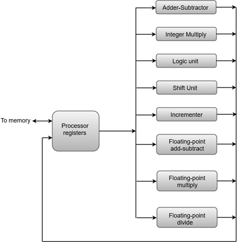
Fig 1 - An operation performed in each functional unit
- The adder and integer multiplier performs the arithmetic operation with integer numbers.
- The floating-point operations are separated into three circuits operating in parallel.
- The logic, shift, and increment operations can be performed concurrently on different data. All units are independent of each other, so one number can be shifted while another number is being incremented.
Key takeaway
Parallel processing can be described as a class of techniques that enables the system to achieve simultaneous data-processing tasks to increase the computational speed of a computer system.
A parallel processing system can carry out simultaneous data-processing to achieve faster execution time. For instance, while an instruction is being processed in the ALU component of the CPU, the next instruction can be read from memory.
The primary purpose of parallel processing is to enhance the computer processing capability and increase its throughput, i.e. the amount of processing that can be accomplished during a given interval of time.
Parallel processing has been developed as an effective technology in modern computers to meet the demand for higher performance, lower cost, and accurate results in real-life applications. Concurrent events are common in today’s computers due to the practice of multiprogramming, multiprocessing, or multi computing.
Modern computers have powerful and extensive software packages. To analyze the development of the performance of computers, first, we have to understand the basic development of hardware and software.
- Computer Development Milestones − There are two major stages of the development of computers - mechanical or electromechanical parts. Modern computers evolved after the introduction of electronic components. High mobility electrons in electronic computers replaced the operational parts in mechanical computers. For information transmission, an electric signal which travels almost at the speed of light replaced mechanical gears or levers.
- Elements of Modern computers − A modern computer system consists of computer hardware, instruction sets, application programs, system software, and user interface.
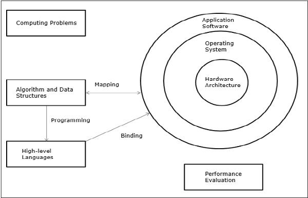
Fig 2 – Elements of modern computers
The computing problems are categorized as numerical computing, logical reasoning, and transaction processing. Some complex problems may need the combination of all three processing modes.
- Evolution of Computer Architecture − In the last four decades, computer architecture has gone through revolutionary changes. We started with Von Neumann architecture and now we have multicomputer and multiprocessors.
- Performance of a computer system − The performance of a computer system depends both on machine capability and program behavior. Machine capability can be improved with better hardware technology, advanced architectural features, and efficient resource management. Program behavior is unpredictable as it is dependent on the application and run-time conditions
Multiprocessors and Multicomputers
In this section, we will discuss two types of parallel computers −
- Multiprocessors
- Multicomputers
Shared-Memory Multicomputers
The three most common shared memory multiprocessors models are −
Uniform Memory Access (UMA)
In this model, all the processors share the physical memory uniformly. All the processors have equal access time to all the memory words. Each processor may have a private cache memory. Same rule is followed for peripheral devices.
When all the processors have equal access to all the peripheral devices, the system is called a symmetric multiprocessor. When only one or a few processors can access the peripheral devices, the system is called an asymmetric multiprocessor.
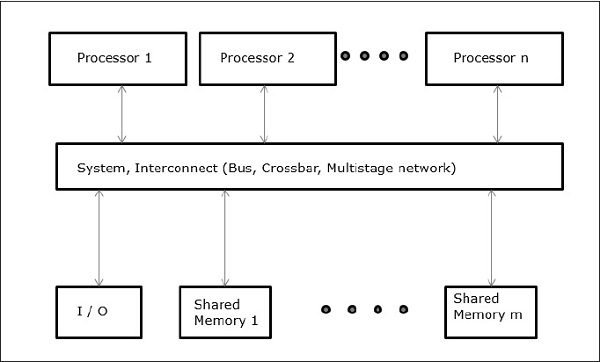
Fig 3 - Uniform Memory Access
Non-uniform Memory Access (NUMA)
In the NUMA multiprocessor model, the access time varies with the location of the memory word. Here, the shared memory is physically distributed among all the processors, called local memories. The collection of all local memories forms a global address space that can be accessed by all the processors.
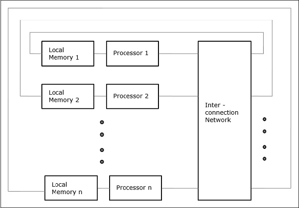
Fig 4 - Non-uniform Memory Access
Cache Only Memory Architecture (COMA)
The COMA model is a special case of the NUMA model. Here, all the distributed main memories are converted to cache memories.
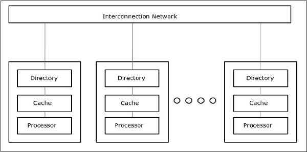
Fig 5- Cache Only Memory Architecture
- Distributed - Memory Multicomputers − A distributed memory multicomputer system consists of multiple computers, known as nodes, interconnected by a message-passing network. Each node acts as an autonomous computer having a processor, local memory, and sometimes I/O devices. In this case, all local memories are private and are accessible only to the local processors. This is why the traditional machines are called no-remote-memory-access (NORMA) machines.
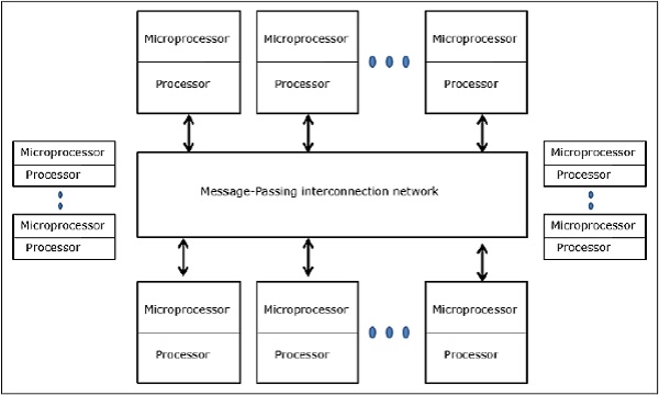
Fig 6 - Distributed - Memory Multicomputers
Multivector and SIMD Computers
In this section, we will discuss supercomputers and parallel processors for vector processing and data parallelism.
Vector Supercomputers
In a vector computer, a vector processor is attached to the scalar processor as an optional feature. The host computer first loads program and data to the main memory. Then the scalar control unit decodes all the instructions. If the decoded instructions are scalar operations or program operations, the scalar processor executes those operations using scalar functional pipelines.
On the other hand, if the decoded instructions are vector operations then the instructions will be sent to the vector control unit.
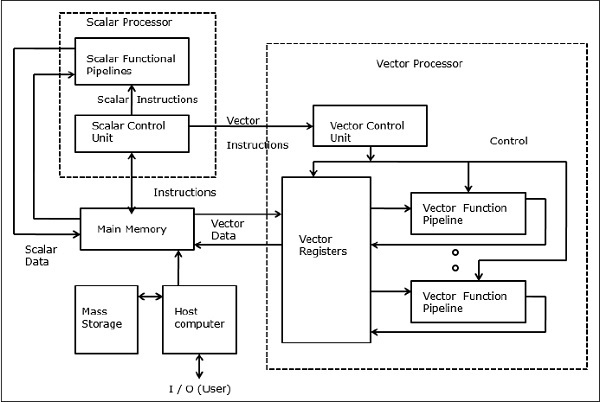
Fig 7 - Vector Supercomputers
SIMD Supercomputers
In SIMD computers, the ‘N’ number of processors are connected to a control unit and all the processors have their memory units. All the processors are connected by an interconnection network.
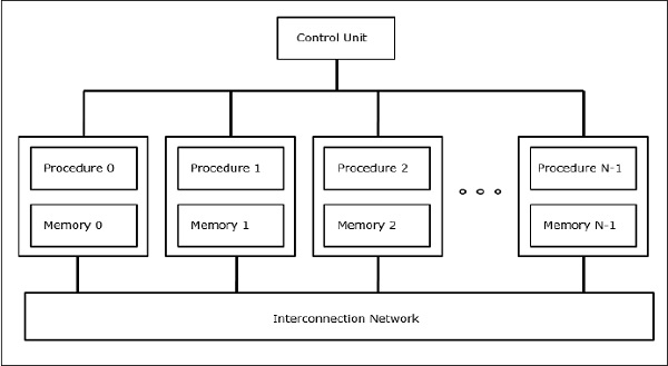
Fig 8 - SIMD Supercomputers
PRAM and VLSI Models
The ideal model gives a suitable framework for developing parallel algorithms without considering the physical constraints or implementation details.
The models can be enforced to obtain theoretical performance bounds on parallel computers or to evaluate VLSI complexity on-chip area and operational time before the chip is fabricated.
Parallel Random-Access Machines
Sheperdson and Sturgis (1963) modeled the conventional Uniprocessor computers as random-access-machines (RAM). Fortune and Wyllie (1978) developed a parallel random-access-machine (PRAM) model for modeling an idealized parallel computer with zero memory access overhead and synchronization.
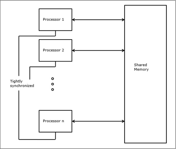
Fig 9 - Parallel Random-Access Machines
An N-processor PRAM has a shared memory unit. This shared memory can be centralized or distributed among the processors. These processors operate on a synchronized read-memory, write-memory, and compute cycle. So, these models specify how concurrent read and write operations are handled.
Following are the possible memory update operations −
- Exclusive read (ER) − In this method, in each cycle, only one processor is allowed to read from any memory location.
- Exclusive write (EW) − In this method, at least one processor is allowed to write into a memory location at a time.
- Concurrent read (CR) − It allows multiple processors to read the same information from the same memory location in the same cycle.
- Concurrent write (CW) − It allows simultaneous write operations to the same memory location. To avoid write conflict some policies are set up.
VLSI Complexity Model
Parallel computers use VLSI chips to fabricate processor arrays, memory arrays, and large-scale switching networks.
Nowadays, VLSI technologies are 2-dimensional. The size of a VLSI chip is proportional to the amount of storage (memory) space available in that chip.
We can calculate the space complexity of an algorithm by the chip area (A) of the VLSI chip implementation of that algorithm. If T is the time (latency) needed to execute the algorithm, then A.T gives an upper bound on the total number of bits processed through the chip (or I/O). For certain computing, there exists a lower bound, f(s), such that
A.T2 >= O (f(s))
Where A=chip area and T=time
Architectural Development Tracks
The evolution of parallel computers I spread along the following tracks −
- Multiple Processor Tracks
- Multiprocessor track
- Multicomputer track
- Multiple data tracks
- Vector track
- SIMD track
- Multiple threads track
- Multithreaded track
- Dataflow track
In a multiple-processor track, it is assumed that different threads execute concurrently on different processors and communicate through shared memory (multiprocessor track) or message passing (multicomputer track) system.
In multiple data tracks, it is assumed that the same code is executed on the massive amount of data. It is done by executing the same instructions on a sequence of data elements (vector track) or through the execution of the same sequence of instructions on a similar set of data (SIMD track).
In multiple threads track, it is assumed that the interleaved execution of various threads on the same processor to hide synchronization delays among threads executing on different processors. Thread interleaving can be coarse (multithreaded track) or fine (dataflow track).
The Cache Coherence Problem
In a multiprocessor system, data inconsistency may occur among adjacent levels or within the same level of the memory hierarchy. For example, the cache and the main memory may have inconsistent copies of the same object.
As multiple processors operating in parallel, and independently multiple caches may possess different copies of the same memory block, this creates a cache coherence problem. Cache coherence schemes help to avoid this problem by maintaining a uniform state for each cached block of data.
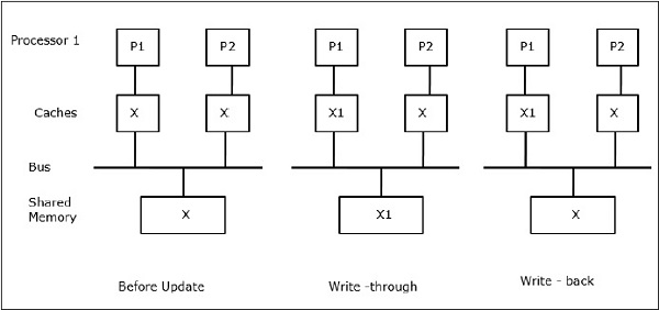
Fig 10 - Cache coherence schemes
Let X be an element of shared data that has been referenced by two processors, P1 and P2. In the beginning, three copies of X are consistent. If the processor P1 writes a new data X1 into the cache, by using a write-through policy, the same copy will be written immediately into the shared memory. In this case, inconsistency occurs between cache memory and the main memory. When a write-back policy is used, the main memory will be updated when the modified data in the cache is replaced or invalidated.
In general, there are three sources of inconsistency problem −
- Sharing of writable data
- Process migration
- I/O activity
Snoopy Bus Protocols
Snoopy protocols achieve data consistency between the cache memory and the shared memory through a bus-based memory system. Write-invalidate and write-update policies are used for maintaining cache consistency.
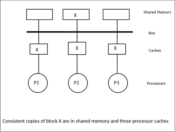
Fig 11 - Snoopy Bus Protocols
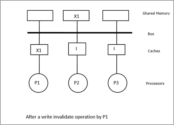
Fig 12 – Example
In this case, we have three processors P1, P2, and P3 having a consistent copy of data element ‘X’ in their local cache memory and the shared memory (Figure-a). Processor P1 writes X1 in its cache memory using the write-invalidate protocol. So, all other copies are invalidated via the bus. It is denoted by ‘I’ (Figure-b). Invalidated blocks are also known as dirty, i.e. they should not be used. The write-update protocol updates all the cache copies via the bus. By using the write-back cache, the memory copy is also updated (Figure-c).
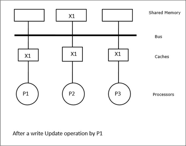
Fig 13 – Example
Cache Events and Actions
Following events and actions occur on the execution of memory-access and invalidation commands −
- Read-miss − When a processor wants to read a block and it is not in the cache, a read-miss occurs. This initiates a bus-read operation. If no dirty copy exists, then the main memory that has a consistent copy supplies a copy to the requesting cache memory. If a dirty copy exists in remote cache memory, that cache will restrain the main memory and send a copy to the requesting cache memory. In both cases, the cached copy will enter the valid state after a read miss.
- Write-hit − If the copy is in a dirty or reserved state, write is done locally and the new state is dirty. If the new state is valid, the write-invalidate command is broadcasted to all the caches, invalidating their copies. When the shared memory is written through, the resulting state is reserved after this first write.
- Write-miss − If a processor fails to write in the local cache memory, the copy must come either from the main memory or from a remote cache memory with a dirty block. This is done by sending a read-invalidate command, which will invalidate all cached copies. Then the local copy is updated with a dirty state.
- Read-hit − Read-hit is always performed in local cache memory without causing a transition of state or using the snoopy bus for invalidation.
- Block replacement − When a copy is dirty, it is to be written back to the main memory by the block replacement method. However, when the copy is either in a valid or reserved, or invalid state, no replacement will take place.
Directory-Based Protocols
By using a multistage network for building a large multiprocessor with hundreds of processors, the snoopy cache protocols need to be modified to suit the network capabilities. Broadcasting being very expensive to perform in a multistage network, the consistency commands are sent only to those caches that keep a copy of the block. This is the reason for the development of directory-based protocols for network-connected multiprocessors.
In a directory-based protocols system, data to be shared are placed in a common directory that maintains the coherence among the caches. Here, the directory acts as a filter where the processors ask permission to load an entry from the primary memory to its cache memory. If an entry is changed the directory either update it or invalidates the other caches with that entry.
Hardware Synchronization Mechanisms
A synchronization is a special form of communication where instead of data control, information is exchanged between communicating processes residing in the same or different processors.
Multiprocessor systems use hardware mechanisms to implement low-level synchronization operations. Most multiprocessors have hardware mechanisms to impose atomic operations such as memory read, write, or read-modify-write operations to implement some synchronization primitives. Other than atomic memory operations, some inter-processor interrupts are also used for synchronization purposes.
Cache Coherency in Shared Memory Machines
Maintaining cache coherency is a problem in the multiprocessor system when the processors contain local cache memory. Data inconsistency between different caches easily occurs in this system.
The major concern areas are −
- Sharing of writable data
- Process migration
- I/O activity
Sharing of writable data
When two processors (P1 and P2) have the same data element (X) in their local caches and one process (P1) writes to the data element (X), as the caches are a write-through local cache of P1, the main memory is also updated. Now when P2 tries to read data element (X), it does not find X because the data element in the cache of P2 has become outdated.
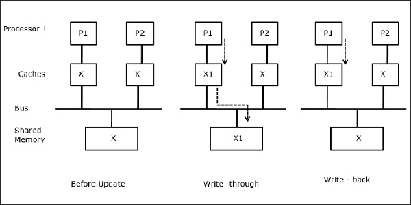
Fig 14 - Sharing of writable data
Process migration
In the first stage, a cache of P1 has data element X, whereas P2 does not have anything. A process on P2 first writes on X and then migrates to P1. Now, the process starts reading data element X, but as the processor P1 has outdated data the process cannot read it. So, a process on P1 writes to the data element X and then migrates to P2. After migration, a process on P2 starts reading the data element X but it finds an outdated version of X in the main memory.
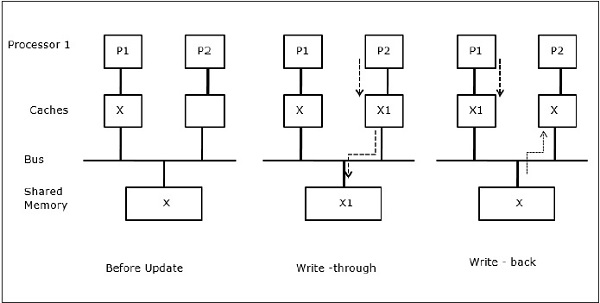
Fig 15 - Process migration
I/O activity
As illustrated in the figure, an I/O device is added to the bus in a two-processor multiprocessor architecture. In the beginning, both the caches contain the data element X. When the I/O device receives a new element X, it stores the new element directly in the main memory. Now, when either P1 or P2 (assume P1) tries to read element X it gets an outdated copy. So, P1 writes to element X. Now, if the I/O device tries to transmit X it gets an outdated copy.
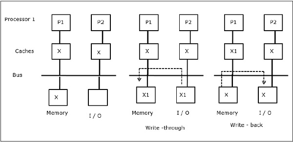
Fig 16 - I/O activity
Uniform Memory Access (UMA)
Uniform Memory Access (UMA) architecture means the shared memory is the same for all processors in the system. Popular classes of UMA machines, which are commonly used for (file-) servers, are the so-called Symmetric Multiprocessors (SMPs). In an SMP, all system resources like memory, disks, other I/O devices, etc. are accessible by the processors in a uniform manner.
Non-Uniform Memory Access (NUMA)
In NUMA architecture, multiple SMP clusters are having an internal indirect/shared network, which is connected in a scalable message-passing network. So, NUMA architecture is logically shared physically distributed memory architecture.
In a NUMA machine, the cache-controller of a processor determines whether a memory reference is local to the SMP’s memory or it is remote. To reduce the number of remote memory accesses, NUMA architectures usually apply caching processors that can cache the remote data. But when caches are involved, cache coherency needs to be maintained. So these systems are also known as CC-NUMA (Cache Coherent NUMA).
Cache Only Memory Architecture (COMA)
COMA machines are similar to NUMA machines, with the only difference that the main memories of COMA machines act as direct-mapped or set-associative caches. The data blocks are hashed to a location in the DRAM cache according to their addresses. Data that is fetched remotely is stored in the local main memory. Moreover, data blocks do not have a fixed home location, they can freely move throughout the system.
COMA architectures mostly have a hierarchical message-passing network. A switch in such a tree contains a directory with data elements as its sub-tree. Since data has no home location, it must be explicitly searched for. This means that remote access requires a traversal along the switches in the tree to search their directories for the required data. So, if a switch in the network receives multiple requests from its subtree for the same data, it combines them into a single request which is sent to the parent of the switch. When the requested data returns, the switch sends multiple copies of it down its subtree.
COMA versus CC-NUMA
Following are the differences between COMA and CC-NUMA.
- COMA tends to be more flexible than CC-NUMA because COMA transparently supports the migration and replication of data without the need for the OS.
- COMA machines are expensive and complex to build because they need non-standard memory management hardware and the coherency protocol is harder to implement.
- Remote accesses in COMA are often slower than those in CC-NUMA since the tree network needs to be traversed to find the data.
Key takeaway
Parallel processing has been developed as an effective technology in modern computers to meet the demand for higher performance, lower cost, and accurate results in real-life applications. Concurrent events are common in today’s computers due to the practice of multiprogramming, multiprocessing, or multi computing.
Modern computers have powerful and extensive software packages. To analyze the development of the performance of computers, first, we have to understand the basic development of hardware and software.
The term Pipelining refers to a technique of decomposing a sequential process into sub-operations, with each sub-operation being executed in a dedicated segment that operates concurrently with all other segments.
The most important characteristic of a pipeline technique is that several computations can be in progress in distinct segments at the same time. The overlapping of computation is made possible by associating a register with each segment in the pipeline. The registers provide isolation between each segment so that each can operate on distinct data simultaneously.
The structure of a pipeline organization can be represented simply by including an input register for each segment followed by a combinational circuit.
Let us consider an example of combined multiplication and addition operation to get a better understanding of the pipeline organization.
The combined multiplication and addition operation is done with a stream of numbers such as:
Ai* Bi + Ci for i = 1, 2, 3, ......., 7
The operation to be performed on the numbers is decomposed into sub-operations with each sub-operation to be implemented in a segment within a pipeline.
The sub-operations performed in each segment of the pipeline are defined as:
R1 ← Ai, R2 ← BiInput Ai, and Bi
R3 ← R1 * R2, R4 ← Ci Multiply, and input Ci
R5 ← R3 + R4Add Ci to product
The following block diagram represents the combined as well as the sub-operations performed in each segment of the pipeline.
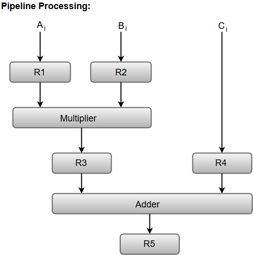
Fig 17 – Pipeline process
Registers R1, R2, R3, and R4 hold the data and the combinational circuits operate in a particular segment.
The output generated by the combinational circuit in a given segment is applied as an input register of the next segment. For instance, from the block diagram, we can see that the register R3 is used as one of the input registers for the combinational adder circuit.
In general, the pipeline organization is applicable for two areas of computer design which includes:
- Arithmetic Pipeline
- Instruction Pipeline
Instruction Pipeline
Pipeline processing can occur not only in the data stream but in the instruction stream as well.
Most digital computers with complex instructions require an instruction pipeline to carry out operations like fetch, decode and execute instructions.
In general, the computer needs to process each instruction with the following sequence of steps.
- Fetch the instruction from memory.
- Decode the instruction.
- Calculate the effective address.
- Fetch the operands from memory.
- Execute the instruction.
- Store the result in the proper place.
Each step is executed in a particular segment, and there are times when different segments may take different times to operate on the incoming information. Moreover, there are times when two or more segments may require memory access at the same time, causing one segment to wait until another is finished with the memory.
The organization of an instruction pipeline will be more efficient if the instruction cycle is divided into segments of equal duration. One of the most common examples of this type of organization is a Four-segment instruction pipeline.
A four-segment instruction pipeline combines two or more different segments and makes it a single one. For instance, the decoding of the instruction can be combined with the calculation of the effective address into one segment.
The following block diagram shows a typical example of a four-segment instruction pipeline. The instruction cycle is completed in four segments.
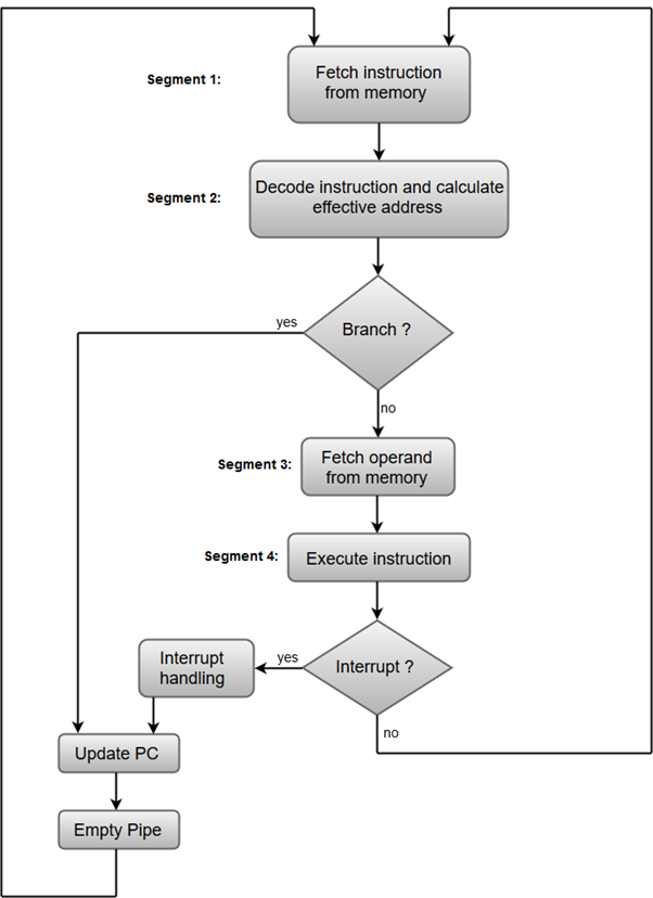
Fig 18 – Instruction Cycle
Segment 1:
The instruction fetch segment can be implemented using a first-in, first-out (FIFO) buffer.
Segment 2:
The instruction fetched from memory is decoded in the second segment, and eventually, the effective address is calculated in a separate arithmetic circuit.
Segment 3:
An operand from memory is fetched in the third segment.
Segment 4:
The instructions are finally executed in the last segment of the pipeline organization.
Arithmetic Pipeline
Arithmetic Pipelines are mostly used in high-speed computers. They are used to implement floating-point operations, multiplication of fixed-point numbers, and similar computations encountered in scientific problems.
To understand the concepts of arithmetic pipeline in a more convenient way, let us consider an example of a pipeline unit for floating-point addition and subtraction.
The inputs to the floating-point adder pipeline are two normalized floating-point binary numbers defined as:
X = A * 2a = 0.9504 * 103
Y = B * 2b = 0.8200 * 102
Where A and B are two fractions that represent the mantissa and a and b are the exponents.
The combined operation of floating-point addition and subtraction is divided into four segments. Each segment contains the corresponding suboperation to be performed in the given pipeline. The suboperations that are shown in the four segments are:
- Compare the exponents by subtraction.
- Align the mantissa.
- Add or subtract the mantissa.
- Normalize the result.
We will discuss each suboperation in a more detailed manner later in this section.
The following block diagram represents the sub-operations performed in each segment of the pipeline.
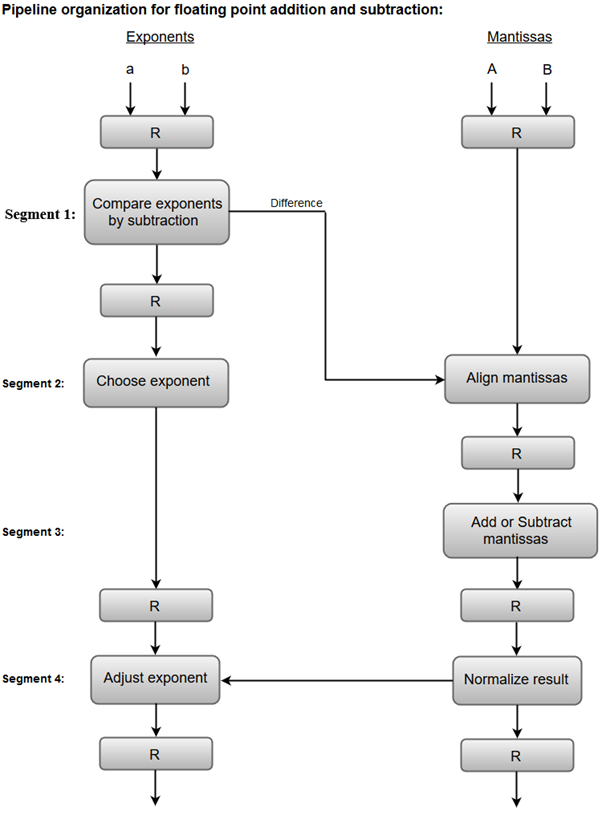
Fig 19 – Sub Operations
Note: Registers are placed after each suboperation to store the intermediate results.
1. Compare exponents by subtraction:
The exponents are compared by subtracting them to determine their difference. The larger exponent is chosen as the exponent of the result.
The difference of the exponents, i.e., 3 - 2 = 1 determines how many times the mantissa associated with the smaller exponent must be shifted to the right.
2. Align the mantissa:
The mantissa associated with the smaller exponent is shifted according to the difference of exponents determined in segment one.
X = 0.9504 * 103
Y = 0.08200 * 103
3. Add mantissas:
The two mantissas are added in segment three.
Z = X + Y = 1.0324 * 103
4. Normalize the result:
After normalization, the result is written as:
Z = 0.1324 * 104
Key takeaway
The term Pipelining refers to a technique of decomposing a sequential process into sub-operations, with each sub-operation being executed in a dedicated segment that operates concurrently with all other segments.
The most important characteristic of a pipeline technique is that several computations can be in progress in distinct segments at the same time. The overlapping of computation is made possible by associating a register with each segment in the pipeline. The registers provide isolation between each segment so that each can operate on distinct data simultaneously.
To improve the performance of a CPU we have two options:
1) Improve the hardware by introducing faster circuits.
2) Arrange the hardware such that more than one operation can be performed at the same time.
Since there is a limit on the speed of hardware and the cost of faster circuits is quite high, we have to adopt the 2nd option.
Pipelining: Pipelining is a process of arrangement of hardware elements of the CPU such that its overall performance is increased. Simultaneous execution of more than one instruction takes place in a pipelined processor.
Let us see a real-life example that works on the concept of pipelined operation. Consider a water bottle packaging plant. Let there be 3 stages that a bottle should pass through, Inserting the bottle(I), Filling water in the bottle(F), and Sealing the bottle(S). Let us consider these stages as stage 1, stage 2, and stage 3 respectively. Let each stage take 1 minute to complete its operation.
Now, in a non pipelined operation, a bottle is first inserted in the plant, after 1 minute it is moved to stage 2 where water is filled. Now, in stage 1 nothing is happening. Similarly, when the bottle moves to stage 3, both stage 1 and stage 2 are idle. But in pipelined operation, when the bottle is in stage 2, another bottle can be loaded at stage 1. Similarly, when the bottle is in stage 3, there can be one bottle each in stage 1 and stage 2. So, after each minute, we get a new bottle at the end of stage 3. Hence, the average time taken to manufacture 1 bottle is :
Without pipelining = 9/3 minutes = 3m
I F S | | | | | |
| | | I F S | | |
| | | | | | I F S (9 minutes)
With pipelining = 5/3 minutes = 1.67m
I F S | |
| I F S |
| | I F S (5 minutes)
Thus, pipelined operation increases the efficiency of a system.
Design of a basic pipeline
- In a pipelined processor, a pipeline has two ends, the input end, and the output end. Between these ends, there are multiple stages/segments such that the output of one stage is connected to the input of the next stage and each stage performs a specific operation.
- Interface registers are used to hold the intermediate output between two stages. These interface registers are also called latch or buffer.
- All the stages in the pipeline along with the interface registers are controlled by a common clock.
Execution in a pipelined processor
Execution sequence of instructions in a pipelined processor can be visualized using a space-time diagram. For example, consider a processor having 4 stages and let there be 2 instructions to be executed. We can visualize the execution sequence through the following space-time diagrams:
Non overlapped execution:
Stage / Cycle | 1 | 2 | 3 | 4 | 5 | 6 | 7 | 8 |
S1 | I1 |
|
|
| I2 |
|
|
|
S2 |
| I1 |
|
|
| I2 |
|
|
S3 |
|
| I1 |
|
|
| I2 |
|
S4 |
|
|
| I1 |
|
|
| I2 |
Fig 20 - Non overlapped execution
Total time = 8 Cycle
Overlapped execution:
Stage / Cycle | 1 | 2 | 3 | 4 | 5 |
S1 | I1 | I2 |
|
|
|
S2 |
| I1 | I2 |
|
|
S3 |
|
| I1 | I2 |
|
S4 |
|
|
| I1 | I2 |
Fig 21 - Overlapped execution
Total time = 5 Cycle
Pipeline Stages
RISC processor has 5 stage instruction pipeline to execute all the instructions in the RISC instruction set. Following are the 5 stages of the RISC pipeline with their respective operations:
- Stage 1 (Instruction Fetch)
In this stage, the CPU reads instructions from the address in the memory whose value is present in the program counter.
- Stage 2 (Instruction Decode)
In this stage, instruction is decoded and the register file is accessed to get the values from the registers used in the instruction.
- Stage 3 (Instruction Execute)
In this stage, ALU operations are performed.
- Stage 4 (Memory Access)
In this stage, memory operands are read and written from/to the memory that is present in the instruction.
- Stage 5 (Write Back)
In this stage, the computed/fetched value is written back to the register present in the instructions.
Performance of a pipelined processor
Consider a ‘k’ segment pipeline with clock cycle time as ‘Tp’. Let there be ‘n’ tasks to be completed in the pipelined processor. Now, the first instruction is going to take ‘k’ cycles to come out of the pipeline but the other ‘n – 1’ instructions will take only ‘1’ cycle each, i.e, a total of ‘n – 1’ cycles. So, time is taken to execute ‘n’ instructions in a pipelined processor:
ETpipeline = k + n – 1 cycles
= (k + n – 1) Tp
In the same case, for a non-pipelined processor, execution time of ‘n’ instructions will be:
ETnon-pipeline = n * k * Tp
So, speedup (S) of the pipelined processor over non-pipelined processor, when ‘n’ tasks are executed on the same processor is:
S = Performance of pipelined processor /
Performance of Non-pipelined processor
As the performance of a processor is inversely proportional to the execution time, we have,
S = ETnon-pipeline / ETpipeline
=> S = [n * k * Tp] / [(k + n – 1) * Tp]
S = [n * k] / [k + n – 1]
When the number of tasks ‘n’ are significantly larger than k, that is, n >> k
S = n * k / n
S = k
Where ‘k’ are the number of stages in the pipeline.
Also, Efficiency = Given speed up / Max speed up = S / Smax
We know that, Smax = k
So, Efficiency = S / k
Throughput = Number of instructions / Total time to complete the instructions
So, Throughput = n / (k + n – 1) * Tp
Note: The cycles per instruction (CPI) value of an ideal pipelined processor is 1
Key takeaway
To improve the performance of a CPU we have two options:
1) Improve the hardware by introducing faster circuits.
2) Arrange the hardware such that more than one operation can be performed at the same time.
Since there is a limit on the speed of hardware and the cost of faster circuits is quite high, we have to adopt the 2nd option.
The objectives of this module are to discuss the various hazards associated with pipelining.
We discussed the basics of pipelining and the MIPS pipeline implementation in the previous module. We made the following observations about pipelining:
- Pipelining doesn’t help latency of single task, it helps throughput of the entire workload
- Pipeline rate limited by slowest pipeline stage o Multiple tasks operating simultaneously
- Potential speedup = Number of pipe stages
- Unbalanced lengths of pipe stages reduce speedup
- Time to “fill” pipeline and time to “drain” reduces speedup o Unbalanced lengths of pipe stages reduces speedup
- Execute billions of instructions, so throughput is what matters o Data path design – Ideally we expect a CPI value of 1
- What is desirable in instruction sets for pipelining?
- Variable-length instructions vs. All instructions same length?
- Memory operands part of any operation vs. Memory operands only in loads or stores?
- Register operand many places in instruction format vs. Registers located in the same place?
Ideally, we expect a CPI value of 1 and a speedup equal to the number of stages in the pipeline. But, some factors limit this. The problems that occur in the pipeline are called hazards. Hazards that arise in the pipeline prevent the next instruction from executing during its designated clock cycle. There are three types of hazards:
- Structural hazards: Hardware cannot support certain combinations of instructions (two instructions in the pipeline require the same resource).
- Data hazards: Instruction depends on the result of prior instruction still in the pipeline
- Control hazards: Caused by the delay between the fetching of instructions and decisions about changes in control flow (branches and jumps).
Structural hazards arise because there is not enough duplication of resources.
Resolving structural hazards:
- Solution 1: Wait
o Must detect the hazard
o Must have a mechanism to stall
o Low cost and simple
o Increases CPI
o Used for rare cases
- Solution 2: Throw more hardware at the problem
o Pipeline hardware resource
§ useful for multi-cycle resources
§ good performance
§ sometimes complex e.g., RAM
o Replicate resource
§ good performance
§ increases cost (+ maybe interconnect delay)
§ useful for cheap or divisible resource
Figure shows one possibility of a structural hazard in the MIPS pipeline. Instruction 3 is accessing memory for an instruction fetch and instruction 1 is accessing memory for the data access (load/store). These two are conflicting requirements and gives rise to a hazard. We should either stall one of the operations as shown in Figure 11.2 or have two separate memories for code and data. Structural hazards will have to be handled at the design time itself.
Next, we shall discuss data dependences and the associated hazards. There are two types of data dependence – true data dependencies and name dependences.
- An instruction j is data-dependent on instruction i if either of the following holds:
– Instruction i produces a result that may be used by instruction j, or
– Instruction j is data-dependent on instruction k, and instruction k is data-dependent on instruction i
- A name dependence occurs when two instructions use the same register or memory location, called a name, but there is no flow of data between the instructions associated with that name
– Two types of name dependencies between an instruction i that precedes instruction j in program order:
– An anti dependence between instruction i and instruction j occurs when instruction j writes a register or memory location that instruction i reads. The original ordering must be preserved.
– An output dependence occurs when instruction i and instruction j write the same register or memory location. The ordering between the instructions must be preserved.
– Since this is not a true dependence, renaming can be more easily done for register operands, where it is called register renaming
– Register renaming can be done either statically by a compiler or dynamically by the hardware
Last, of all, we discuss control dependences. Control dependencies determine the ordering of an instruction with respect to a branch instruction so that an instruction i is executed in the correct program order. There are two general constraints imposed by control dependences:
– An instruction that is control dependent on its branch cannot be moved before the branch so that its execution is no longer controlled by the branch.
– An instruction that is not controlled dependent on its branch cannot be moved after the branch so that its execution is controlled by the branch.
Having introduced the various types of data dependencies and control dependence, let us discuss how these dependencies cause problems in the pipeline. Dependences are properties of programs and whether the dependences turn out to be hazards and cause stalls in the pipeline are properties of the pipeline organization.
Data hazards may be classified as one of three types, depending on the order of reading and write accesses in the instructions:
- RAW (Read After Write)
- Corresponds to a true data dependence
- Program order must be preserved
- This hazard results from an actual need for communication
- Considering two instructions i and j, instruction j reads the data before i writes it
i: ADD R1, R2, R3
j: SUB R4, R1, R3
Add modifies R1 and then Sub should read it. If this order is changed, there is a RAW hazard
- WAW (Write After Write)
- Corresponds to an output dependence
- Occurs when there are multiple writes or a short integer pipeline and a longer floating-point pipeline or when an instruction proceeds when a previous instruction is stalled WAW (write after write)
- This is caused by a name dependence. There is no actual data transfer. It is the same name that causes the problem
- Considering two instructions i and j, instruction j should write after instruction i has written the data
i: SUB R1, R4, R3
j: ADD R1, R2, R3
Instruction i have to modify register r1 first, and then j has to modify it. Otherwise, there is a WAW hazard. There is a problem because of R1. If some other register had been used, there will not be a problem
- The solution is register renaming, that is, use some other register. The hardware can do the renaming or the compiler can do the renaming
- WAR (Write After Read)
- Arises from an anti dependence
- Cannot occur in most static issue pipelines
- Occurs either when there are early writes and late reads, or when instructions are re-ordered
- There is no actual data transfer. It is the same name that causes the problem
- Considering two instructions i and j, instruction j should write after instruction i has read the data.
i: SUB R4, R1, R3
j: ADD R1, R2, R3
Instruction i has to read register r1 first, and then j has to modify it. Otherwise, there is a WAR hazard. There is a problem because of R1. If some other register had been used, there will not be a problem
• Solution is register renaming, that is, use some other register. The hardware can do the renaming or the compiler can do the renaming
Figure 11.3 gives a situation of having true data dependencies. The use of the result of the ADD instruction in the next three instructions causes a hazard since the register is not written until after those instructions read it. The write-back for the ADD instruction happens only in the fifth clock cycle, whereas the next three instructions read the register values before that, and hence will read the wrong data. This gives rise to RAW hazards.
A control hazard is when we need to find the destination of a branch, and can’t fetch any new instructions until we know that destination. Figure 11.4 illustrates a control hazard. The first instruction is a branch and it gets resolved only in the fourth clock cycle. So, the next three instructions fetched may be correct, or wrong, depending on the outcome of the branch. This is an example of a control hazard.
Now, having discussed the various dependencies and the hazards that they might lead to, we shall see what are the hazards that can happen in our simple MIPS pipeline.
- Structural hazard
- Conflict for use of a resource
- In MIPS pipeline with a single memory
– Load/store requires data access
– Instruction fetch would have to stall for that cycle
- Would cause a pipeline “bubble”
- Hence, pipelined datapaths require separate instruction/data memories or separate instruction/data caches
- RAW hazards – can happen in any architecture
- WAR hazards – Can’t happen in MIPS 5 stage pipeline because all instructions take 5 stages, and reads are always in stage 2, and writes are always in stage 5
- WAW hazards – Can’t happen in MIPS 5 stage pipeline because all instructions take 5 stages, and writes are always in stage 5
- Control hazards
- Can happen
- The penalty depends on when the branch is resolved – in the second clock cycle or the third clock cycle
- More aggressive implementations resolve the branch in the second clock cycle itself, leading to one clock cycle penalty
Let us look at the speedup equation with stalls and look at an example problem.
CPIpipelined = Ideal CPI + Average Stall cycles per Inst
Let us assume we want to compare the performance of two machines. Which machine is faster?
- Machine A: Dual ported memory – so there are no memory stalls
- Machine B: Single ported memory, but its pipelined implementation has a 1.05 times faster clock rate
Assume:
- Ideal CPI = 1 for both
- Loads are 40% of instructions executed
SpeedupA = Pipeline Depth/(1+0) x(clockunpipe/clockpipe)
= Pipeline Depth
SpeedupB = Pipeline Depth/(1 + 0.4 x 1) x (clockunpipe/(clockunpipe / 1.05)
= (Pipeline Depth/1.4) x 1.05
= 75 x Pipeline Depth
SpeedupA / SpeedupB = Pipeline Depth / (0.75 x Pipeline Depth) = 1.33 Machine A is 1.33 times faster.
To summarize, we have discussed the various hazards that might occur in a pipeline. Structural hazards happen because there is not enough duplication of resources and they have to be handled at design time itself. Data hazards happen because of true data dependencies and name dependences. Control hazards are caused by branches. The solutions for all these hazards will be discussed in the subsequent modules.
Key takeaway
- Pipelining doesn’t help latency of a single task, it helps throughput of the entire workload
- Pipeline rate limited by slowest pipeline stage o Multiple tasks operating simultaneously
- Potential speedup = Number of pipe stages
- Unbalanced lengths of pipe stages reduce speedup
- Time to “fill” pipeline and time to “drain” reduces speedup o Unbalanced lengths of pipe stages reduces speedup
- Execute billions of instructions, so throughput is what matters o Data path design – Ideally we expect a CPI value of 1
References:
1. “Computer Organization and Design: The Hardware/Software Interface”, 5th Edition by David A. Patterson and John L. Hennessy, Elsevier.
2. “Computer Organization and Embedded Systems”, 6th Edition by Carl Hamacher, McGraw Hill Higher Education.
3. “Computer Architecture and Organization”, 3rd Edition by John P. Hayes, WCB/McGraw-Hill
4. “Computer Organization and Architecture: Designing for Performance”, 10th Edition by William Stallings, Pearson Education.
5. “Computer System Design and Architecture”, 2nd Edition by Vincent P. Heuring and Harry F. Jordan, Pearson Education.