Unit - 2
Disk space management
There are various methods which can be used to allocate disk space to the files. Selection of an appropriate allocation method will significantly affect the performance and efficiency of the system. Allocation method provides a way in which the disk will be utilized and the files will be accessed.
There are following methods which can be used for allocation.
- Contiguous Allocation.
- Extents
- Linked Allocation
- Clustering
- FAT
- Indexed Allocation
- Linked Indexed Allocation
- Multilevel Indexed Allocation
- Inode
Contiguous Allocation
If the blocks are allocated to the file in such a way that all the logical blocks of the file get the contiguous physical block in the hard disk then such allocation scheme is known as contiguous allocation.
In the image shown below, there are three files in the directory. The starting block and the length of each file are mentioned in the table. We can check in the table that the contiguous blocks are assigned to each file as per its need.
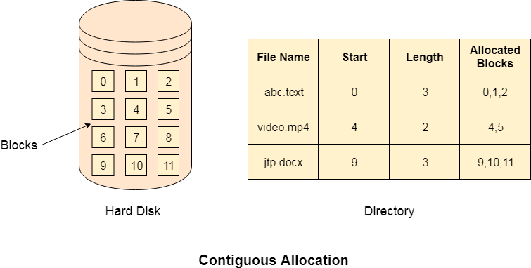
Fig 1: Contiguous allocation
Advantages
- It is simple to implement.
- We will get Excellent read performance.
- Supports Random Access into files.
Disadvantages
- The disk will become fragmented.
- It may be difficult to have a file grow.
Linked List Allocation
Linked List allocation solves all problems of contiguous allocation. In linked list allocation, each file is considered as the linked list of disk blocks. However, the disks blocks allocated to a particular file need not to be contiguous on the disk. Each disk block allocated to a file contains a pointer which points to the next disk block allocated to the same file.

Fig 2: Linked list allocation
Advantages
- There is no external fragmentation with linked allocation.
- Any free block can be utilized in order to satisfy the file block requests.
- File can continue to grow as long as the free blocks are available.
- Directory entry will only contain the starting block address.
Disadvantages
- Random Access is not provided.
- Pointers require some space in the disk blocks.
- Any of the pointers in the linked list must not be broken otherwise the file will get corrupted.
- Need to traverse each block.
Indexed Allocation
Limitation of FAT
Limitation in the existing technology causes the evolution of a new technology. Till now, we have seen various allocation methods; each of them was carrying several advantages and disadvantages.
File allocation table tries to solve as many problems as possible but leads to a drawback. The more the number of blocks, the more will be the size of FAT.
Therefore, we need to allocate more space to a file allocation table. Since, file allocation table needs to be cached therefore it is impossible to have as many space in cache. Here we need a new technology which can solve such problems.
Indexed Allocation Scheme
Instead of maintaining a file allocation table of all the disk pointers, Indexed allocation scheme stores all the disk pointers in one of the blocks called as indexed block. Indexed block doesn't hold the file data, but it holds the pointers to all the disk blocks allocated to that particular file. Directory entry will only contain the index block address.
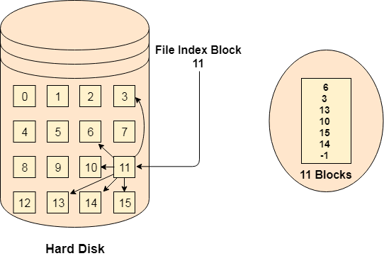
Fig 3: Index allocation
Advantages
- Supports direct access
- A bad data block causes the lost of only that block.
Disadvantages
- A bad index block could cause the lost of entire file.
- Size of a file depends upon the number of pointers, a index block can hold.
- Having an index block for a small file is totally wastage.
- More pointer overhead
Key takeaway
There are various methods which can be used to allocate disk space to the files. Selection of an appropriate allocation method will significantly affect the performance and efficiency of the system. Allocation method provides a way in which the disk will be utilized and the files will be accessed.
File Directories
A single directory may or may not contain multiple files. It can also have subdirectories inside the main directory. Information about files is maintained by Directories. In Windows OS, it is called folders.
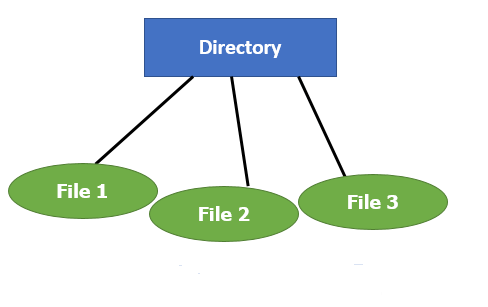
Fig 4: Single Level Directory
Following is the information which is maintained in a directory:
- Name The name which is displayed to the user.
- Type: Type of the directory.
- Position: Current next-read/write pointers.
- Location: Location on the device where the file header is stored.
- Size: Number of bytes, block, and words in the file.
- Protection: Access control on read/write/execute/delete.
- Usage: Time of creation, access, modification
File types- name, extension
File Type | Usual extension | Function |
Executable | Exe, com, bin or none | Ready-to-run machine- language program |
Object | Obj, o | Complied, machine language, not linked |
Source code | c. p, pas, 177, asm, a | Source code in various languages |
Batch | Bat, sh | Series of commands to be executed |
Text | Txt, doc | Textual data documents |
Word processor | Doc,docs, tex, rrf, etc. | Various word-processor formats |
Library | Lib, h | Libraries of routines |
Archive | Arc, zip, tar | Related files grouped into one file, sometimes compressed. |
Summary:
- A file is a collection of correlated information which is recorded on secondary or non-volatile storage like magnetic disks, optical disks, and tapes.
- It provides I/O support for a variety of storage device types.
- Files are stored on disk or other storage and do not disappear when a user logs off.
- A File Structure needs to be predefined format in such a way that an operating system understands it.
- File type refers to the ability of the operating system to differentiate different types of files like text files, binary, and source files.
- Create find space on disk and make an entry in the directory.
- Indexed Sequential Access method is based on simple sequential access
- In Sequential Access method records are accessed in a certain predefined sequence
- The random access method is also called direct random access
- Three types of space allocation methods are:
- Linked Allocation
- Indexed Allocation
- Contiguous Allocation
- Information about files is maintained by Directories
File directories
What is a directory?
The directory can be defined as the listing of the related files on the disk. The directory may store some or the entire file attributes.
To get the benefit of different file systems on the different operating systems, A hard disk can be divided into some partitions of different sizes. The partitions are also called volumes or minidisks.
Each partition must have at least one directory in which, all the files of the partition can be listed. A directory entry is maintained for each file in the directory which stores all the information related to that file.
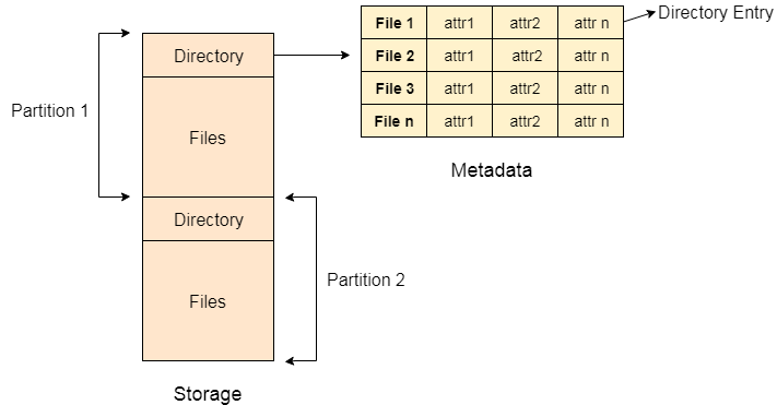
Fig 5: Example
A directory can be viewed as a file that contains the Metadata of a bunch of files.
Every Directory supports many common operations on the file:
- File Creation
- Search for the file
- File deletion
- Renaming the file
- Traversing Files
- Listing of files
Single Level Directory
The simplest method is to have one big list of all the files on the disk. The entire system will contain only one directory which is supposed to mention all the files present in the file system. The directory contains one entry per each file present on the file system.
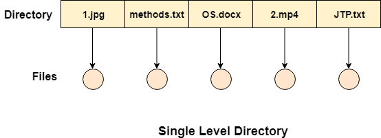
Fig 6: Single level directory
This type of directories can be used for a simple system.
Advantages
- Implementation is very simple.
- If the sizes of the files are very small then the searching becomes faster.
- File creation, searching, deletion is very simple since we have only one directory.
Disadvantages
- We cannot have two files with the same name.
- The directory may be very big therefore searching for a file may take so much time.
- Protection cannot be implemented for multiple users.
- There are no ways to group the same kind of files.
- Choosing the unique name for every file is a bit complex and limits the number of files in the system because most of the Operating System limits the number of characters used to construct the file name.
Two Level Directory
In two-level directory systems, we can create a separate directory for each user. There is one master directory that contains separate directories dedicated to each user. For each user, there is a different directory present at the second level, containing a group of user's files. The system doesn't let a user enter the other user's directory without permission.
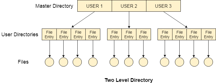
Fig 7: Two-Level Directory
Characteristics of the two-level directory system
- Each file has a pathname as /User-name/directory-name/
- Different users can have the same file name.
- Searching becomes more efficient as only one user's list needs to be traversed.
- The same kind of files cannot be grouped into a single directory for a particular user.
Every Operating System maintains a variable as PWD which contains the present directory name (present user name) so that the searching can be done appropriately.
Key takeaway
The directory can be defined as the listing of the related files on the disk. The directory may store some or the entire file attributes.
To get the benefit of different file systems on the different operating systems, A hard disk can be divided into some partitions of different sizes. The partitions are also called volumes or minidisks.
As we know, a process needs two type of time, CPU time and IO time. For I/O, it requests the Operating system to access the disk.
However, the operating system must be fair enough to satisfy each request and at the same time, operating system must maintain the efficiency and speed of process execution.
The technique that operating system uses to determine the request which is to be satisfied next is called disk scheduling.
Let's discuss some important terms related to disk scheduling.
Seek Time
Seek time is the time taken in locating the disk arm to a specified track where the read/write request will be satisfied.
Rotational Latency
It is the time taken by the desired sector to rotate itself to the position from where it can access the R/W heads.
Transfer Time
It is the time taken to transfer the data.
Disk Access Time
Disk access time is given as,
Disk Access Time = Rotational Latency + Seek Time + Transfer Time
Disk Response Time
It is the average of time spent by each request waiting for the IO operation.
Purpose of Disk Scheduling
The main purpose of disk scheduling algorithm is to select a disk request from the queue of IO requests and decide the schedule when this request will be processed.
Goal of Disk Scheduling Algorithm
- Fairness
- High throughout
- Minimal traveling head time
Disk Scheduling Algorithms
The list of various disks scheduling algorithm is given below. Each algorithm is carrying some advantages and disadvantages. The limitation of each algorithm leads to the evolution of a new algorithm.
- FCFS scheduling algorithm
- SSTF (shortest seek time first) algorithm
- SCAN scheduling
- C-SCAN scheduling
- LOOK Scheduling
- C-LOOK scheduling
FCFS Scheduling Algorithm
It is the simplest Disk Scheduling algorithm. It services the IO requests in the order in which they arrive. There is no starvation in this algorithm, every request is serviced.
Disadvantages
- The scheme does not optimize the seek time.
- The request may come from different processes therefore there is the possibility of inappropriate movement of the head.
Example
Consider the following disk request sequence for a disk with 100 tracks 45, 21, 67, 90, 4, 50, 89, 52, 61, 87, 25
Head pointer starting at 50 and moving in left direction. Find the number of head movements in cylinders using FCFS scheduling.
Solution
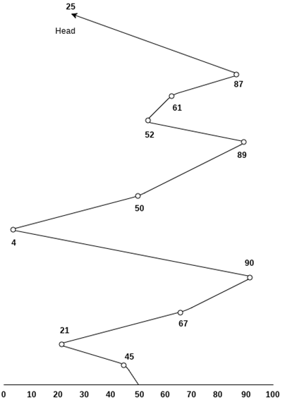
Number of cylinders moved by the head
= (50-45)+(45-21)+(67-21)+(90-67)+(90-4)+(50-4)+(89-50)+(61-52)+(87-61)+(87-25)
= 5 + 24 + 46 + 23 + 86 + 46 + 49 + 9 + 26 + 62
= 376
SSTF Scheduling Algorithm
Shortest seek time first (SSTF) algorithm selects the disk I/O request which requires the least disk arm movement from its current position regardless of the direction. It reduces the total seek time as compared to FCFS.
It allows the head to move to the closest track in the service queue.
Disadvantages
- It may cause starvation for some requests.
- Switching direction on the frequent basis slows the working of algorithm.
- It is not the most optimal algorithm.
Example
Consider the following disk request sequence for a disk with 100 tracks
45, 21, 67, 90, 4, 89, 52, 61, 87, 25
Head pointer starting at 50. Find the number of head movements in cylinders using SSTF scheduling.
Solution:
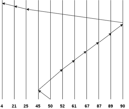
Number of cylinders = 5 + 7 + 9 + 6 + 20 + 2 + 1 + 65 + 4 + 17 = 136
SCAN and C-SCAN algorithm
Scan Algorithm
It is also called as Elevator Algorithm. In this algorithm, the disk arm moves into a particular direction till the end, satisfying all the requests coming in its path and then it turns back and moves in the reverse direction satisfying requests coming in its path.
It works in the way an elevator works, elevator moves in a direction completely till the last floor of that direction and then turns back.
Example
Consider the following disk request sequence for a disk with 100 tracks
98, 137, 122, 183, 14, 133, 65, 78
Head pointer starting at 54 and moving in left direction. Find the number of head movements in cylinders using SCAN scheduling.
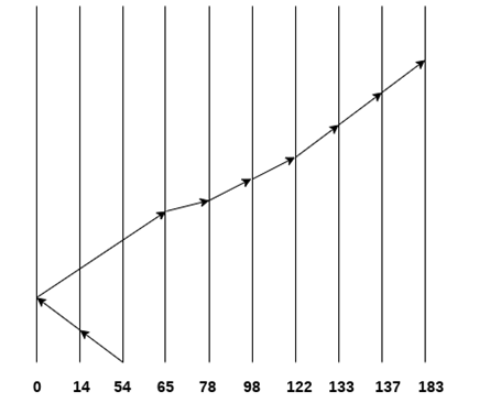
Number of Cylinders = 40 + 14 + 65 + 13 + 20 + 24 + 11 + 4 + 46 = 237
C-SCAN algorithm
In C-SCAN algorithm, the arm of the disk moves in a particular direction servicing requests until it reaches the last cylinder, then it jumps to the last cylinder of the opposite direction without servicing any request then it turns back and start moving in that direction servicing the remaining requests.
Example
Consider the following disk request sequence for a disk with 100 tracks
98, 137, 122, 183, 14, 133, 65, 78
Head pointer starting at 54 and moving in left direction. Find the number of head movements in cylinders using C-SCAN scheduling.
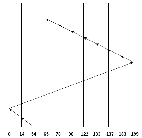
No. Of cylinders crossed = 40 + 14 + 199 + 16 + 46 + 4 + 11 + 24 + 20 + 13 = 387
Key takeaway
As we know, a process needs two type of time, CPU time and IO time. For I/O, it requests the Operating system to access the disk.
However, the operating system must be fare enough to satisfy each request and at the same time, operating system must maintain the efficiency and speed of process execution.
The technique that operating system uses to determine the request which is to be satisfied next is called disk scheduling.
Process
A process is basically a program in execution. The execution of a process must progress in a sequential fashion.
A process is defined as an entity which represents the basic unit of work to be implemented in the system.
To put it in simple terms, we write our computer programs in a text file and when we execute this program, it becomes a process which performs all the tasks mentioned in the program.
When a program is loaded into the memory and it becomes a process, it can be divided into four sections ─ stack, heap, text and data. The following image shows a simplified layout of a process inside main memory −
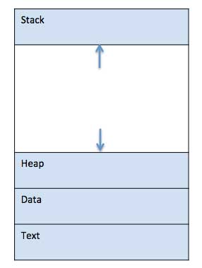
Fig 8 - A simplified layout of a process inside main memory
S.N. | Component & Description |
1 | Stack The process Stack contains the temporary data such as method/function parameters, return address and local variables. |
2 | Heap This is dynamically allocated memory to a process during its run time. |
3 | Text This includes the current activity represented by the value of Program Counter and the contents of the processor's registers. |
4 | Data This section contains the global and static variables. |
Program
A program is a piece of code which may be a single line or millions of lines. A computer program is usually written by a computer programmer in a programming language. For example, here is a simple program written in C programming language −
#include <stdio.h>
Int main() {
printf("Hello, World! \n");
return 0;
}
A computer program is a collection of instructions that performs a specific task when executed by a computer. When we compare a program with a process, we can conclude that a process is a dynamic instance of a computer program.
A part of a computer program that performs a well-defined task is known as an algorithm. A collection of computer programs, libraries and related data are referred to as a software.
Process Life Cycle
When a process executes, it passes through different states. These stages may differ in different operating systems, and the names of these states are also not standardized.
In general, a process can have one of the following five states at a time.
S.N. | State & Description |
1 | Start This is the initial state when a process is first started/created. |
2 | Ready The process is waiting to be assigned to a processor. Ready processes are waiting to have the processor allocated to them by the operating system so that they can run. Process may come into this state after Start state or while running it by but interrupted by the scheduler to assign CPU to some other process. |
3 | Running Once the process has been assigned to a processor by the OS scheduler, the process state is set to running and the processor executes its instructions. |
4 | Waiting Process moves into the waiting state if it needs to wait for a resource, such as waiting for user input, or waiting for a file to become available. |
5 | Terminated or Exit Once the process finishes its execution, or it is terminated by the operating system, it is moved to the terminated state where it waits to be removed from main memory. |
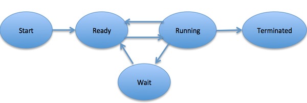
Fig 9 – Process state
A Process Control Block is a data structure maintained by the Operating System for every process. The PCB is identified by an integer process ID (PID). A PCB keeps all the information needed to keep track of a process as listed below in the table −
S.N. | Information & Description |
1 | Process State The current state of the process i.e., whether it is ready, running, waiting, or whatever. |
2 | Process privileges This is required to allow/disallow access to system resources. |
3 | Process ID Unique identification for each of the process in the operating system. |
4 | Pointer A pointer to parent process. |
5 | Program Counter Program Counter is a pointer to the address of the next instruction to be executed for this process. |
6 | CPU registers Various CPU registers where process need to be stored for execution for running state. |
7 | CPU Scheduling Information Process priority and other scheduling information which is required to schedule the process. |
8 | Memory management information This includes the information of page table, memory limits, Segment table depending on memory used by the operating system. |
9 | Accounting information This includes the amount of CPU used for process execution, time limits, execution ID etc. |
10 | IO status information This includes a list of I/O devices allocated to the process. |
The architecture of a PCB is completely dependent on Operating System and may contain different information in different operating systems. Here is a simplified diagram of a PCB −
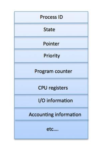
Fig 10: PCB
Key takeaway
A process is basically a program in execution. The execution of a process must progress in a sequential fashion.
A process is defined as an entity which represents the basic unit of work to be implemented in the system.
To put it in simple terms, we write our computer programs in a text file and when we execute this program, it becomes a process which performs all the tasks mentioned in the program.
Definition
The process scheduling is the activity of the process manager that handles the removal of the running process from the CPU and the selection of another process on the basis of a particular strategy.
Process scheduling is an essential part of a Multiprogramming operating systems. Such operating systems allow more than one process to be loaded into the executable memory at a time and the loaded process shares the CPU using time multiplexing.
Process Scheduling Queues
The OS maintains all PCBs in Process Scheduling Queues. The OS maintains a separate queue for each of the process states and PCBs of all processes in the same execution state are placed in the same queue. When the state of a process is changed, its PCB is unlinked from its current queue and moved to its new state queue.
The Operating System maintains the following important process scheduling queues −
- Job queue − This queue keeps all the processes in the system.
- Ready queue − This queue keeps a set of all processes residing in main memory, ready and waiting to execute. A new process is always put in this queue.
- Device queues − The processes which are blocked due to unavailability of an I/O device constitute this queue.
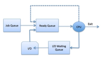
Fig 11 – Process state
The OS can use different policies to manage each queue (FIFO, Round Robin, Priority, etc.). The OS scheduler determines how to move processes between the ready and run queues which can only have one entry per processor core on the system; in the above diagram, it has been merged with the CPU.
Two-State Process Model
Two-state process model refers to running and non-running states which are described below −
S.N. | State & Description |
1 | Running When a new process is created, it enters into the system as in the running state. |
2 | Not Running Processes that are not running are kept in queue, waiting for their turn to execute. Each entry in the queue is a pointer to a particular process. Queue is implemented by using linked list. Use of dispatcher is as follows. When a process is interrupted, that process is transferred in the waiting queue. If the process has completed or aborted, the process is discarded. In either case, the dispatcher then selects a process from the queue to execute. |
Schedulers
Schedulers are special system software which handle process scheduling in various ways. Their main task is to select the jobs to be submitted into the system and to decide which process to run. Schedulers are of three types −
- Long-Term Scheduler
- Short-Term Scheduler
- Medium-Term Scheduler
Long Term Scheduler
It is also called a job scheduler. A long-term scheduler determines which programs are admitted to the system for processing. It selects processes from the queue and loads them into memory for execution. Process loads into the memory for CPU scheduling.
The primary objective of the job scheduler is to provide a balanced mix of jobs, such as I/O bound and processor bound. It also controls the degree of multiprogramming. If the degree of multiprogramming is stable, then the average rate of process creation must be equal to the average departure rate of processes leaving the system.
On some systems, the long-term scheduler may not be available or minimal. Time-sharing operating systems have no long-term scheduler. When a process changes the state from new to ready, then there is use of long-term scheduler.
Short Term Scheduler
It is also called as CPU scheduler. Its main objective is to increase system performance in accordance with the chosen set of criteria. It is the change of ready state to running state of the process. CPU scheduler selects a process among the processes that are ready to execute and allocates CPU to one of them.
Short-term schedulers, also known as dispatchers, make the decision of which process to execute next. Short-term schedulers are faster than long-term schedulers.
Medium Term Scheduler
Medium-term scheduling is a part of swapping. It removes the processes from the memory. It reduces the degree of multiprogramming. The medium-term scheduler is in-charge of handling the swapped out-processes.
A running process may become suspended if it makes an I/O request. A suspended process cannot make any progress towards completion. In this condition, to remove the process from memory and make space for other processes, the suspended process is moved to the secondary storage. This process is called swapping, and the process is said to be swapped out or rolled out. Swapping may be necessary to improve the process mix.
Comparison among Scheduler
S.N. | Long-Term Scheduler | Short-Term Scheduler | Medium-Term Scheduler |
1 | It is a job scheduler | It is a CPU scheduler | It is a process swapping scheduler. |
2 | Speed is lesser than short term scheduler | Speed is fastest among other two | Speed is in between both short- and long-term scheduler. |
3 | It controls the degree of multiprogramming | It provides lesser control over degree of multiprogramming | It reduces the degree of multiprogramming. |
4 | It is almost absent or minimal in time sharing system | It is also minimal in time sharing system | It is a part of Time-sharing systems. |
5 | It selects processes from pool and loads them into memory for execution | It selects those processes which are ready to execute | It can re-introduce the process into memory and execution can be continued. |
Key takeaway
The process scheduling is the activity of the process manager that handles the removal of the running process from the CPU and the selection of another process on the basis of a particular strategy.
Process scheduling is an essential part of a Multiprogramming operating systems. Such operating systems allow more than one process to be loaded into the executable memory at a time and the loaded process shares the CPU using time multiplexing.
The Context switching is a technique or method used by the operating system to switch a process from one state to another to execute its function using CPUs in the system. When switching perform in the system, it stores the old running process's status in the form of registers and assigns the CPU to a new process to execute its tasks. While a new process is running in the system, the previous process must wait in a ready queue. The execution of the old process starts at that point where another process stopped it. It defines the characteristics of a multitasking operating system in which multiple processes shared the same CPU to perform multiple tasks without the need for additional processors in the system.
The need for Context switching
A context switching helps to share a single CPU across all processes to complete its execution and store the system's tasks status. When the process reloads in the system, the execution of the process starts at the same point where there is conflicting.
Following are the reasons that describe the need for context switching in the Operating system.
- The switching of one process to another process is not directly in the system. A context switching helps the operating system that switches between the multiple processes to use the CPU's resource to accomplish its tasks and store its context. We can resume the service of the process at the same point later. If we do not store the currently running process's data or context, the stored data may be lost while switching between processes.
- If a high priority process falls into the ready queue, the currently running process will be shut down or stopped by a high priority process to complete its tasks in the system.
- If any running process requires I/O resources in the system, the current process will be switched by another process to use the CPUs. And when the I/O requirement is met, the old process goes into a ready state to wait for its execution in the CPU. Context switching stores the state of the process to resume its tasks in an operating system. Otherwise, the process needs to restart its execution from the initials level.
- If any interrupts occur while running a process in the operating system, the process status is saved as registers using context switching. After resolving the interrupts, the process switches from a wait state to a ready state to resume its execution at the same point later, where the operating system interrupted occurs.
- A context switching allows a single CPU to handle multiple process requests simultaneously without the need for any additional processors.
Example of Context Switching
Suppose that multiple processes are stored in a Process Control Block (PCB). One process is running state to execute its task with the use of CPUs. As the process is running, another process arrives in the ready queue, which has a high priority of completing its task using CPU. Here we used context switching that switches the current process with the new process requiring the CPU to finish its tasks. While switching the process, a context switch saves the status of the old process in registers. When the process reloads into the CPU, it starts the execution of the process when the new process stops the old process. If we do not save the state of the process, we have to start its execution at the initial level. In this way, context switching helps the operating system to switch between the processes, store or reload the process when it requires executing its tasks.
Context switching triggers
Following are the three types of context switching triggers as follows.
- Interrupts
- Multitasking
- Kernel/User switch
Interrupts: A CPU requests for the data to read from a disk, and if there are any interrupts, the context switching automatic switches a part of the hardware that requires less time to handle the interrupts.
Multitasking: A context switching is the characteristic of multitasking that allows the process to be switched from the CPU so that another process can be run. When switching the process, the old state is saved to resume the process's execution at the same point in the system.
Kernel/User Switch: It is used in the operating systems when switching between the user mode, and the kernel/user mode is performed.
What is the PCB?
A PCB (Process Control Block) is a data structure used in the operating system to store all data related information to the process. For example, when a process is created in the operating system, updated information of the process, switching information of the process, terminated process in the PCB.
Steps for Context Switching
There are several steps involves in context switching of the processes. The following diagram represents the context switching of two processes, P1 to P2, when an interrupt, I/O needs, or priority-based process occurs in the ready queue of PCB.
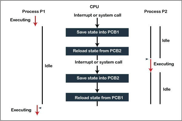
Fig 12 - The context switching of two processes
As we can see in the diagram, initially, the P1 process is running on the CPU to execute its task, and at the same time, another process, P2, is in the ready state. If an error or interruption has occurred or the process requires input/output, the P1 process switches its state from running to the waiting state. Before changing the state of the process P1, context switching saves the context of the process P1 in the form of registers and the program counter to the PCB1. After that, it loads the state of the P2 process from the ready state of the PCB2 to the running state.
The following steps are taken when switching Process P1 to Process 2:
- First, this context switching needs to save the state of process P1 in the form of the program counter and the registers to the PCB (Program Counter Block), which is in the running state.
- Now update PCB1 to process P1 and moves the process to the appropriate queue, such as the ready queue, I/O queue and waiting queue.
- After that, another process gets into the running state, or we can select a new process from the ready state, which is to be executed, or the process has a high priority to execute its task.
- Now, we have to update the PCB (Process Control Block) for the selected process P2. It includes switching the process state from ready to running state or from another state like blocked, exit, or suspend.
- If the CPU already executes process P2, we need to get the status of process P2 to resume its execution at the same time point where the system interrupt occurs.
Similarly, process P2 is switched off from the CPU so that the process P1 can resume execution. P1 process is reloaded from PCB1 to the running state to resume its task at the same point. Otherwise, the information is lost, and when the process is executed again, it starts execution at the initial level.
Key takeaway
The Context switching is a technique or method used by the operating system to switch a process from one state to another to execute its function using CPUs in the system. When switching perform in the system, it stores the old running process's status in the form of registers and assigns the CPU to a new process to execute its tasks. While a new process is running in the system, the previous process must wait in a ready queue. The execution of the old process starts at that point where another process stopped it. It defines the characteristics of a multitasking operating system in which multiple processes shared the same CPU to perform multiple tasks without the need for additional processors in the system.
There is the way of thread execution within the method of any software. With the exception of this, there may be quite one thread within a method. Thread is usually cited as a light-weight method.
The process may be reduction into such a big amount of threads. For instance, in an exceedingly browser, several tabs may be viewed as threads. MS Word uses several threads - data format text from one thread, process input from another thread, etc.
Types of Threads
In the software, there square measure 2 sorts of threads.
- Kernel level thread.
- User-level thread.
User-level thread
The software doesn't acknowledge the user-level thread. User threads may be simply enforced and it's enforced by the user. If a user performs a user-level thread obstruction operation, the complete method is blocked. The kernel level thread doesn't unskilled person regarding the user level thread. The kernel-level thread manages user-level threads as if they're single-threaded processes? Examples: Java thread, POSIX threads, etc.
Advantages of User-level threads
- The user threads may be simply enforced than the kernel thread.
- User-level threads may be applied to such sorts of in operation systems that don't support threads at the kernel-level.
- It's quicker and economical.
- Context switch time is shorter than the kernel-level threads.
- It doesn't need modifications of the software.
- User-level threads illustration is extremely easy. The register, PC, stack, and mini thread management blocks square measure hold on within the address house of the user-level method.
- It's easy to form, switch, and synchronize threads while not the intervention of the method.
Disadvantages of User-level threads
- User-level threads lack coordination between the thread and therefore the kernel.
- If a thread causes a page fault, the whole method is blocked.
Kernel level thread
The kernel thread acknowledges the software. There square measure a thread management block and method management block within the system for every thread and method within the kernel-level thread. The kernel-level thread is enforced by the software. The kernel is aware of regarding all the threads and manages them. The kernel-level thread offers a supervisor call instruction to form and manage the threads from user-space. The implementation of kernel threads is troublesome than the user thread. Context switch time is longer within the kernel thread. If a kernel thread performs a obstruction operation, the Banky thread execution will continue. Example: Window Solaris.
Advantages of Kernel-level threads
- The kernel-level thread is totally tuned in to all threads.
- The hardware might conceive to pay additional time within the process of threads being giant numerical.
- The kernel-level thread is nice for those applications that block the frequency.
Disadvantages of Kernel-level threads
- The kernel thread manages and schedules all threads.
- The implementation of kernel threads is troublesome than the user thread.
- The kernel-level thread is slower than user-level threads.
Components of Threads
Any thread has the subsequent parts.
- Program counter
- Register set
- Stack house
Benefits of Threads
- Enhanced outturn of the system: once the method is split into several threads, and every thread is treated as employment, the quantity of jobs worn out the unit time will increase. That's why the outturn of the system additionally will increase.
- Effective Utilization of digital computer system: after you have quite one thread in one method, you'll be able to schedule quite one thread in additional than one processor.
- Faster context switch: The context shift amount between threads is a smaller amount than the method context shift. The method context switch suggests that additional overhead for the hardware.
- Responsiveness: once the method is split into many threads, and once a thread completes its execution, that method may be suffered as before long as doable.
- Communication: Multiple-thread communication is easy as a result of the threads share an equivalent address house, whereas in method, we have a tendency to adopt simply some exclusive communication methods for communication between 2 processes.
- Resource sharing: Resources may be shared between all threads at intervals a method, like code, data, and files. Note: The stack and register can't be shared between threads. There square measure a stack and register for every thread.
Thread State Diagram
Appearing on your screen may be a thread state diagram. Let's take a more in-depth explore the various states showing on the diagram.
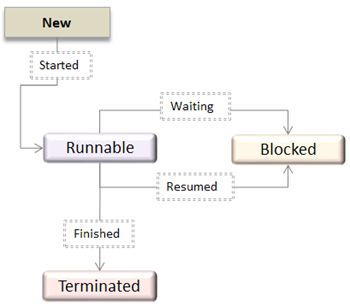
Fig 13 - OS Thread State Diagram
A thread is within the new state once it's been created. It does not take any hardware resources till it's really running. Now, the method is taking on hardware resources as a result of it's able to run. However, it's in an exceedingly runnable state as a result of it might be looking forward to another thread to run and then it's to attend for its flip.
A thread that isn't allowed to continue remains in an exceedingly blocked state. Parenthetically that a thread is looking forward to input/output (I/O), however it ne'er gets those resources, therefore it'll stay in an exceedingly blocked state. The great news is that a blocked thread will not use hardware resources. The thread is not stopped forever. For instance, if you permit emergency vehicles to pass, it doesn't mean that you just square measure forever barred from your final destination. Similarly, those threads (emergency vehicles) that have the next priority square measure processed prior to you. If a thread becomes blocked, another thread moves to the front of the road. However, this is often accomplished is roofed within the next section regarding programming and context shift.
Finally, a thread is terminated if it finishes a task with success or abnormally. At this time, no hardware resources square measure used.
Difference between User-Level & Kernel-Level Thread
S.N. | User-Level Threads | Kernel-Level Thread |
1 | User-level threads are faster to create and manage. | Kernel-level threads are slower to create and manage. |
2 | Implementation is by a thread library at the user level. | Operating system supports creation of Kernel threads. |
3 | User-level thread is generic and can run on any operating system. | Kernel-level thread is specific to the operating system. |
4 | Multi-threaded applications cannot take advantage of multiprocessing. | Kernel routines themselves can be multithreaded. |
Key takeaway
There is a way of thread execution inside the process of any operating system. Apart from this, there can be more than one thread inside a process. Thread is often referred to as a lightweight process.
The process can be split down into so many threads. For example, in a browser, many tabs can be viewed as threads. MS Word uses many threads - formatting text from one thread, processing input from another thread, etc.
Some operating system provides a combined user level thread and Kernel level thread facility. Solaris is a good example of this combined approach. In a combined system, multiple threads within the same application can run in parallel on multiple processors and a blocking system call need not block the entire process. Multithreading models are three types
- Many to many relationship.
- Many to one relationship.
- One to one relationship.
Many to Many Model
The many-to-many model multiplexes any number of user threads onto an equal or smaller number of kernel threads.
The following diagram shows the many-to-many threading model where 6 user level threads are multiplexing with 6 kernel level threads. In this model, developers can create as many user threads as necessary and the corresponding Kernel threads can run in parallel on a multiprocessor machine. This model provides the best accuracy on concurrency and when a thread performs a blocking system call, the kernel can schedule another thread for execution.
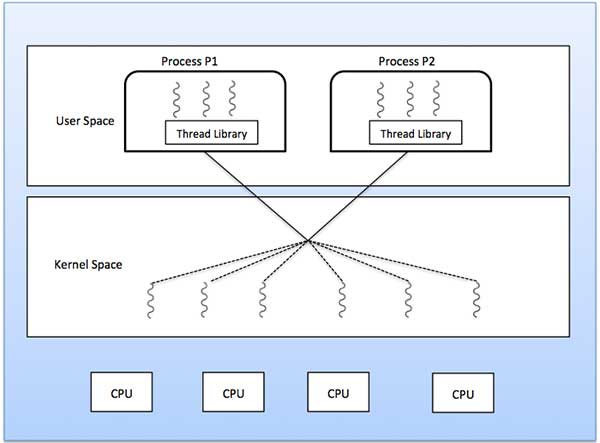
Fig 14 - The best accuracy on concurrency
Many to One Model
Many-to-one model maps many users level threads to one Kernel-level thread. Thread management is done in user space by the thread library. When thread makes a blocking system call, the entire process will be blocked. Only one thread can access the Kernel at a time, so multiple threads are unable to run in parallel on multiprocessors.
If the user-level thread libraries are implemented in the operating system in such a way that the system does not support them, then the Kernel threads use the many-to-one relationship modes.
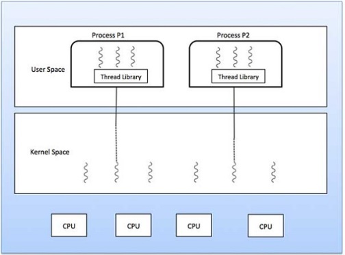
Fig 15 – Many to one model
One to One Model
There is one-to-one relationship of user-level thread to the kernel-level thread. This model provides more concurrency than the many-to-one model. It also allows another thread to run when a thread makes a blocking system call. It supports multiple threads to execute in parallel on microprocessors.
Disadvantage of this model is that creating user thread requires the corresponding Kernel thread. OS/2, windows NT and windows 2000 use one to one relationship model.
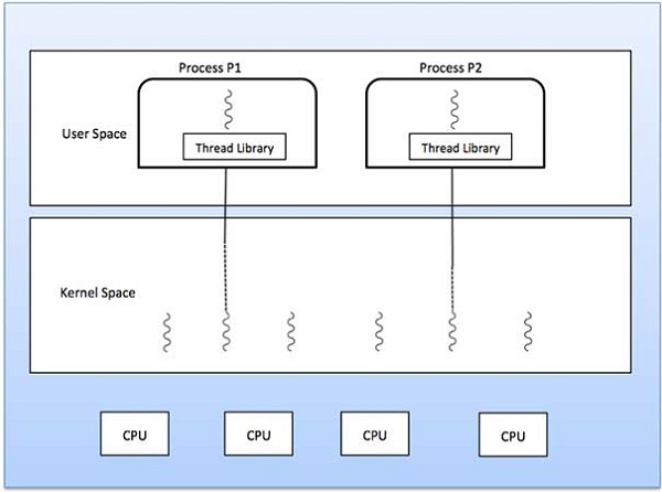
Fig 16 – One to one model
A Process Scheduler schedules different processes to be assigned to the CPU based on particular scheduling algorithms. There are six popular process scheduling algorithms which we are going to discuss in this chapter −
- First-Come, First-Served (FCFS) Scheduling
- Shortest-Job-Next (SJN) Scheduling
- Priority Scheduling
- Shortest Remaining Time
- Round Robin (RR) Scheduling
- Multiple-Level Queues Scheduling
These algorithms are either non-pre-emptive or pre-emptive. Non-pre-emptive algorithms are designed so that once a process enters the running state, it cannot be pre-empted until it completes its allotted time, whereas the pre-emptive scheduling is based on priority where a scheduler may pre-empt a low priority running process anytime when a high priority process enters into a ready state.
First Come First Serve (FCFS)
- Jobs are executed on first come, first serve basis.
- It is a non-pre-emptive, pre-emptive scheduling algorithm.
- Easy to understand and implement.
- Its implementation is based on FIFO queue.
- Poor in performance as average wait time is high.
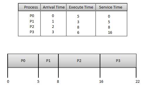
Wait time of each process is as follows −
Process | Wait Time: Service Time - Arrival Time |
P0 | 0 - 0 = 0 |
P1 | 5 - 1 = 4 |
P2 | 8 - 2 = 6 |
P3 | 16 - 3 = 13 |
Average Wait Time: (0+4+6+13) / 4 = 5.75
Shortest Job Next (SJN)
- This is also known as shortest job first, or SJF
- This is a non-pre-emptive, pre-emptive scheduling algorithm.
- Best approach to minimize waiting time.
- Easy to implement in Batch systems where required CPU time is known in advance.
- Impossible to implement in interactive systems where required CPU time is not known.
- The processer should know in advance how much time process will take.
Given: Table of processes, and their Arrival time, Execution time
Process | Arrival Time | Execution Time | Service Time |
P0 | 0 | 5 | 0 |
P1 | 1 | 3 | 5 |
P2 | 2 | 8 | 14 |
P3 | 3 | 6 | 8 |
Waiting time of each process is as follows −
Process | Waiting Time |
P0 | 0 - 0 = 0 |
P1 | 5 - 1 = 4 |
P2 | 14 - 2 = 12 |
P3 | 8 - 3 = 5 |
Average Wait Time: (0 + 4 + 12 + 5)/4 = 21 / 4 = 5.25
Priority Based Scheduling
- Priority scheduling is a non-pre-emptive algorithm and one of the most common scheduling algorithms in batch systems.
- Each process is assigned a priority. Process with highest priority is to be executed first and so on.
- Processes with same priority are executed on first come first served basis.
- Priority can be decided based on memory requirements, time requirements or any other resource requirement.
Given: Table of processes, and their Arrival time, Execution time, and priority. Here we are considering 1 is the lowest priority.
Process | Arrival Time | Execution Time | Priority | Service Time |
P0 | 0 | 5 | 1 | 0 |
P1 | 1 | 3 | 2 | 11 |
P2 | 2 | 8 | 1 | 14 |
P3 | 3 | 6 | 3 | 5 |
Waiting time of each process is as follows −
Process | Waiting Time |
P0 | 0 - 0 = 0 |
P1 | 11 - 1 = 10 |
P2 | 14 - 2 = 12 |
P3 | 5 - 3 = 2 |
Average Wait Time: (0 + 10 + 12 + 2)/4 = 24 / 4 = 6
Shortest Remaining Time
- Shortest remaining time (SRT) is the pre-emptive version of the SJN algorithm.
- The processor is allocated to the job closest to completion but it can be pre-empted by a newer ready job with shorter time to completion.
- Impossible to implement in interactive systems where required CPU time is not known.
- It is often used in batch environments where short jobs need to give preference.
Round Robin Scheduling
- Round Robin is the pre-emptive process scheduling algorithm.
- Each process is provided a fix time to execute, it is called a quantum.
- Once a process is executed for a given time period, it is pre-empted and other process executes for a given time period.
- Context switching is used to save states of pre-empted processes.
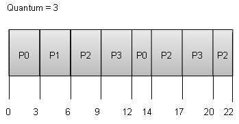
Wait time of each process is as follows −
Process | Wait Time: Service Time - Arrival Time |
P0 | (0 - 0) + (12 - 3) = 9 |
P1 | (3 - 1) = 2 |
P2 | (6 - 2) + (14 - 9) + (20 - 17) = 12 |
P3 | (9 - 3) + (17 - 12) = 11 |
Average Wait Time: (9+2+12+11) / 4 = 8.5
Multiple-Level Queues Scheduling
Multiple-level queues are not an independent scheduling algorithm. They make use of other existing algorithms to group and schedule jobs with common characteristics.
- Multiple queues are maintained for processes with common characteristics.
- Each queue can have its own scheduling algorithms.
- Priorities are assigned to each queue.
For example, CPU-bound jobs can be scheduled in one queue and all I/O-bound jobs in another queue. The Process Scheduler then alternately selects jobs from each queue and assigns them to the CPU based on the algorithm assigned to the queue.
Key takeaway
A Process Scheduler schedules different processes to be assigned to the CPU based on particular scheduling algorithms. There are six popular process scheduling algorithms which we are going to discuss in this chapter −
- First-Come, First-Served (FCFS) Scheduling
- Shortest-Job-Next (SJN) Scheduling
- Priority Scheduling
- Shortest Remaining Time
- Round Robin (RR) Scheduling
- Multiple-Level Queues Scheduling
References:
1. Operating Systems (5th Ed) - Internals and Design Principles by William Stallings, Prentice Hall India, 2000.
2. Operating System: Concepts and Design by Milan Milenkovik, McGraw Hill Higher Education.
3. Operating Systems - 3rd Edition by Gary Nutt, Pearson Education.
4. Operating Systems, 3rd Edition by P. Balakrishna Prasad, SciTech Publications.