Unit - 4
Introduction to Embedded System
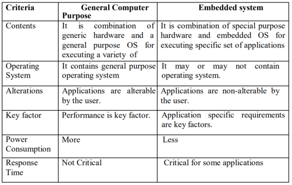
The Embedded System and the General-purpose computer are at two extremes. The embedded system is designed to perform a specific task whereas as per definition the general-purpose computer is meant for general use. It can be used for playing games, watching movies, creating software, work on documents or spreadsheets etc.
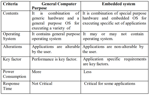
Following are certain specific points of difference between embedded systems and general-purpose computers:
- The first recognised embedded system is the Apollo Guidance Computer (AGC) developed by MIT lab.
- AGC was designed on 4K words of ROM & 256 words of RAM.
- The clock frequency of first microchip used in AGC was 1.024 MHz.
- The computing unit of AGC consists of 11 instructions and 16-bit word logic.
- It used 5000 ICs.
- The UI of AGC is known DSKY (display/keyboard) which resembles a calculator type keypad with array of numerals.
- The first mass-produced embedded system was guidance computer for the Minuteman-I missile in 1961.
- In the year 1971 Intel introduced the world's first microprocessor chip called the 4004, was designed for use in business calculators. It was produced by the Japanese company Busicom.
Embedded systems can be classified into different types based on performance, functional requirements and performance of the microcontroller.
Types of Embedded systems
Embedded systems are classified into four categories based on their performance and functional requirements:
- Stand alone embedded systems
- Real time embedded systems
- Networked embedded systems
- Mobile embedded systems
Embedded Systems are classified into three types based on the performance of the microcontroller such as
- Small scale embedded systems
- Medium scale embedded systems
- Sophisticated embedded systems
Stand Alone Embedded Systems
Stand alone embedded systems do not require a host system like a computer, it works by itself. It takes the input from the input ports either analog or digital and processes, calculates and converts the data and gives the resulting data through the connected device-Which either controls, drives and displays the connected devices. Examples for the stand alone embedded systems are mp3 players, digital cameras, video game consoles, microwave ovens and temperature measurement systems.
Real Time Embedded Systems
A real time embedded system is defined as, a system which gives a required o/p in a particular time. These types of embedded systems follow the time deadlines for completion of a task. Real time embedded systems are classified into two types such as soft and hard real time systems.
Networked Embedded Systems
These types of embedded systems are related to a network to access the resources. The connected network can be LAN, WAN or the internet. The connection can be any wired or wireless. This type of embedded system is the fastest growing area in embedded system applications. The embedded web server is a type of system wherein all embedded devices are connected to a web server and accessed and controlled by a web browser. Example for the LAN networked embedded system is a home security system wherein all sensors are connected and run on the protocol TCP/IP.
Mobile Embedded Systems
Mobile embedded systems are used in portable embedded devices like cell phones, mobiles, digital cameras, mp3 players and personal digital assistants, etc. The basic limitation of these devices is the other resources and limitation of memory.
Small Scale Embedded Systems
These types of embedded systems are designed with a single 8 or 16-bit microcontroller, that may even be activated by a battery. For developing embedded software for small scale embedded systems, the main programming tools are an editor, assembler, cross assembler and integrated development environment (IDE).
Medium Scale Embedded Systems
These types of embedded systems design with a single or 16 or 32 bit microcontroller, RISCs or DSPs. These types of embedded systems have both hardware and software complexities. For developing embedded software for medium scale embedded systems, the main programming tools are C, C++, JAVA, Visual C++, RTOS, debugger, source code engineering tool, simulator and IDE.
Sophisticated Embedded Systems
These types of embedded systems have enormous hardware and software complexities, that may need ASIPs, IPs, PLAs, scalable or configurable processors. They are used for cutting-edge applications that need hardware and software Co-design and components which have to assemble in the final system.
- C and C++ programming
- Microcontrollers, or MCUs
- Microprocessors
- Linux operating system
- Software optimizations skills at the System on a Chip (SoC) level
- Real-time Operating Systems (RTOS)
- Device drivers
- Understanding of design patterns and embedded system design patterns
- Debugging skills
- Ability to work with existing codebases
- Interrupt-driven design
- Assembly programming language
- Hardware test equipment: oscilloscope, logic analyser.
- Experience in or ability to learn communication protocols. Relevant protocols to have at least an understanding of include I2C, Serial Peripheral Interface (SPI), USB, General-purpose input/output (GPIOs), Controller Area Network (CAN bus), Recommended Standard 232 (RS232), one-wire, Recommended Standard 485 (RS485)
- Ability to read a schematic
- Basic understanding of Internet of Things (IoT) and internet-based technologies
- Understanding of data structures
- Python programming language
- RISC-V instruction set architecture
A Design Metric is a measurable feature of the system’s performance, cost, time for implementation and safety etc. Most of these are conflicting requirements i.e. optimizing one shall not optimize the other: e.g. a cheaper processor may have a lousy performance as far as speed and throughput is concerned. Following metrics are generally taken into account while designing embedded systems.
NRE cost (nonrecurring engineering cost)
It is one-time cost of designing the system. Once the system is designed, any number of units can be manufactured without incurring any additional design cost; hence the term nonrecurring. Suppose three technologies are available for use in a particular product. Assume that implementing the product using technology ‘A’ would result in an NRE cost of $2,000 and unit cost of $100, that technology B would have an NRE cost of $30,000 and unit cost of $30, and that technology C would have an NRE cost of $100,000 and unit cost of $2. Ignoring all other design metrics, like time-to-market, the best technology choice will depend on the number of units we plan to produce.
Unit cost
The monetary cost of manufacturing each copy of the system, excluding NRE cost.
Size
The physical space required by the system, often measured in bytes for software, and gates or transistors for hardware. Performance The execution time of the system
Power Consumption
It is the amount of power consumed by the system, which may determine the lifetime of a battery, or the cooling requirements of the IC, since more power means more heat.
Flexibility
The ability to change the functionality of the system without incurring heavy NRE cost. Software is typically considered very flexible.
Time-to-prototype
The time needed to build a working version of the system, which may be bigger or more expensive than the final system implementation, but it can be used to verify the system’s usefulness and correctness and to refine the system’s functionality.
Time-to-market
The time required to develop a system to the point that it can be released and sold to customers. The main contributors are design time, manufacturing time, and testing time. This metric has become especially demanding in recent years. Introducing an embedded system to the marketplace early can make a big difference in the system’s profitability.
Maintainability
It is the ability to modify the system after its initial release, especially by designers who did not originally design the system.
Correctness
This is the measure of the confidence that we have implemented the system’s functionality correctly. We can check the functionality throughout the process of designing the system, and we can insert test circuitry to check that manufacturing was correct.
An embedded system can be a computer hardware system having software embedded in it. An embedded system can be an independent system or it can be a part of a large system. An embedded system is a microcontroller or microprocessor-based system designed to perform a specific task.
For example, let us consider the fire alarm as an embedded system. This system only senses smoke.
An embedded system consists of three components −
- It has hardware.
- It has application software.
- It has a Real Time Operating system (RTOS) which defines the way the system works. It sets the rules during the execution of the application program. A small-scale embedded system may not have RTOS.
Characteristics of an Embedded System
- Single-functioned − An embedded system usually performs a specialized operation and does the same repeatedly. For example: A pager always functions as a pager.
- Tightly constrained − All computing systems have constraints on design metrics, but those on an embedded system can be especially tight. Design metrics is a measure of an implementation's features such as its cost, size, power, and performance
- Reactive and Real time − Many embedded systems must continually react to changes in the system's environment and must compute certain results in real time without any delay.
- Memory − It must have a memory, as its software usually embeds in ROM. It does not need any secondary memories in the computer.
- Connected − It must have connected peripherals to connect input and output devices.
- HW-SW systems − Software is used for more features and flexibility. Hardware is used for performance and security.
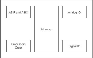
A processor has two essential units
- Program Flow Control Unit (CU)
- Execution Unit (EU)
The CU includes a fetch unit for fetching instructions from the memory. The EU has circuits that implement the instructions pertaining to data transfer operation and data conversion from one form to another.
The EU includes the Arithmetic and Logical Unit (ALU) and also the circuits that execute instructions for a program control task such as interrupt, or jump to another set of instructions. A processor runs the cycles of fetch and executes the instructions in the same sequence as they are fetched from memory.
Types of Processors
Processors can be of the following categories
- General Purpose Processor (GPP)
- Microprocessor o Microcontroller
- Embedded Processor
- Digital Signal Processor
- Media Processor
- Application Specific System Processor (ASSP)
- Application Specific Instruction Processors (ASIPs)
The Embedded system hardware includes elements like user interface, Input/Output interfaces, display and memory, etc. Generally an embedded system comprises power supply, processor, memory, timers, serial communication ports and system application specific circuits
The software embeds into hardware. Hardware consists of number of building blocks in a circuit board or in ASIC or on the SoC along with the processors. Hardware consists of following building blocks and devices in a system in general.
- Power Source: Various units in an embedded system operate in one of the ranges 5.0V±0,25 V. 3_3 V ±0.3V 2.0 V ±0,2 V and 1.5V± 0 2V.
- Clock Oscillator and Clocking Unit(s): The clock controls the time for executing an instruction, The frequency depends on the processor circuit execution rate.
- System Timer: A timer circuit is suitably configured and functions as system dock. The system clock ticks and generates system-interrupts periodically. The system-clock interrupt enables execution of the system supervisory functions in the OS at the periodic intervals. System clock ticks can be 60 times in second.
- Real-Time Clock (RTC): A real-time clock is required in a system. The clock drives the timers for various timing and counting needs in a system. The clock also updates time and date in the system. A microcontroller provides the timer circuits for the counting and tuning devices.
- Reset Circuit, Power-up Reset and Watchdog-Timer Reset A circuit for reset enables restart of the system from the beginning using a switch or signal. The reset can also be performed by using an instruction to the processor. A power-up reset circuit enables restart of the system from beginning whenever power is switched on in the system. A watchdog-timer reset enables the restart of system when it is stuck up in certain set of instructions for a period more than preset time-interval. Reset based on reset-switch, reset-instruction or power-up or power-up reset and watchdog reset can be from same starting instruction or the different starting instructions.
- Memory Various forms of memories are used in a system. Figure shows a chart for the various forms of memories that are present in systems. These are as follows:
- Internal RAM
- Internal ROM/PROM/EPROM
- External RAM for the temporary data and stack (in most systems)
- Internal caches (in pipelined and superscalar microprocessors)
- Internal EEPROM or flash (I) Memory Stick (card): video, images, songs, or speeches and large storage in digital camera, mobile systems
- External ROM or PROM for embedding soft are (in almost all other than microcontrollers-based systems)
- RAM Memory buffers at the ports
- Digital to Analog conversion (ADC): DAC is a circuit that converts digital 8, 10 r 12 bits to analog output. A DAC operation is done with the help of a combination of the Pulse Width Modulation (PWM) unit in a microcontroller and an external integrator chip.
- Analog to Digital Conversion (ADC): ADC is a circuit that converts the analog input to digital. The output is of 4, 8 10 or 12 bits from an ADC. Analog input is applied between + and – pins. ADC circuit converts them into bits. The converted bits value depends on the reference voltage. When input +ve and -ve pins are at voltage equal to reference +ve and -ve voltage pins, then all output bits = 1. When the difference in voltage at inputs +ve and -ve pins = 0v then all output bits = 0. An ADC unit in the embedded system microcontroller may have multi channels. It can then take the inputs in succession from the various interconnected to different analog sources.
- LED, LCD and Touch-Screen Displays: A system requires an interfacing circuit and software to display. LED is used for indicating ON status of the system. A flashing LED may indicate that, a specific task is under completion or is running. It may indicate a wait status for a message. The display may show the status or message. Display may be a line display, a multiline display or a flashing display. An LSI (Lower scale integrated circuit) is used as display controller in case of the LCD matrix display. Touch screen is an input as well as output device, which is used by the user of a system to enter a command, choose a menu or to give user reply as input. The input is on physical touch as a screen position. The touch at a position is mostly by the finger or some times by stylus. Stylus is a thin pencil shaped long object. It is held between the fingers and used just as a pen to mark a dot. An LSI (Lower scale integrated circuit) functions as touch-screen controller. The display-screen display is similar to a computer display unit screen
- Keypad, Keyboard or Virtual Keypad at touch screen: The keypad or keyboard, is an important device for getting user inputs. A touch screen provides virtual keypad in a mobile computing system. Virtual keypad is a keypad displayed on displayed on the LCD display screen on touch plate. A user can enter the inputs using touches. A tile is displayed for a command on the LCD display screen. User can enter the command using touch at the tile. A keypad or keyboard may interface to a system. The system may provide necessary interfacing circuit and software to receive inputs directly from the keys or touch screen controller
- Interrupt Handler: A system may process a number of devices. The system processor controls and handles the requirements of each device by running an appropriate ISR for each interrupting event, An interrupts-handling mechanism must exist in each system. It handles interrupts from various events or processors in the system. The system handled multiple interrupts, which may be simultaneously pending for service.
An embedded system processor and the system need software that is specific to a given application of that system. The processor of the system processes the instruction codes in data. In the final stage, these are placed in the memory ROM. For all the tasks that have been executed. The final state software is also called ROM Image. Each code or datum is available only in bits and bytes format. The system requires bits Each ram address, according to the task being executed. A machine implement able software file is there for like. Table of address and bits at. Each address of the system memory the table has to be read. Azar Ram image. For the targeted hardware. The figure below shows the ROM image. In our system memory. The image consists of the boot up program, commerce stack, address pointer, program counter, address pointer, application task, ISR, RTOS, input data, and vector addresses.
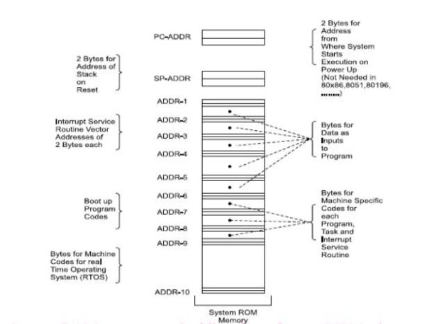
- ROM image
- Programming Languages
- Program models
ROM Image
- Final stage software also called ROM image
- Just as an image is a unique sequence and arrangement of
- Pixels, embedded software is also a unique placement and
- Arrangement at each ROM address of bytes for instructions and data
Final machine software
- Bytes at each address defined for creating the ROM image
- By changing this image, the same hardware platform work
- Differently and can be used for entirely different applications or
- For new upgrades of the same system.
- Hardware elements between the distinct systems can be identical but it is the software that makes a system unique and distinct from the other.
Compressed Codes and Data
ROM image may alternatively be compressed software (for example, the zip format) and data (for example, the pictures in jpg or gif format) along with the software required for decompression algorithm
Programming Languages
1. Machine Language Coding
- Programmer defines the addresses and the corresponding bytes or bits at each address
- Used in configuring some specific physical device or subsystem like transceiver, the machine code- based coding is used
2. Assembly Language Coding
- Needed for Invoking Processor Specific Instructions
- Requires understanding of the processor and instruction set
- A program or a small specific part coded in the assembly language using an Assembler (software used for developing codes in assembly).
Three steps when using assembly language
- 'Assembler',
- 'Linker' and
- 'Locator’
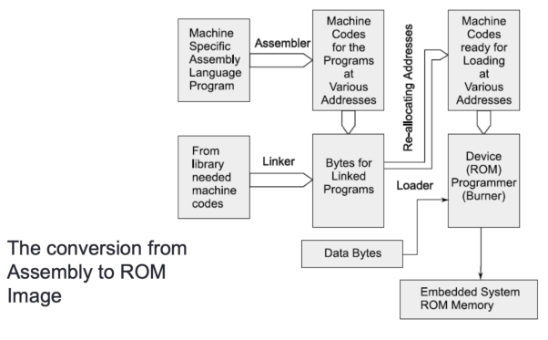
Before finally burned at the ROM
Program various layers
- Processor commands
- Main function
- Task functions and
- Library functions
- Interrupt service routines and kernel (scheduler)
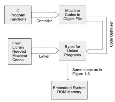
Compiler -Generates an object file. Using linker and locator, the file for ROM image is created for the targeted hardware. C++ and Java are other languages used for software coding.
Program Models
- Sequential Programming Model
- Object Oriented Programming Model
- Control and Data flow graphs or Synchronous Data Flow (SDF) Graph or Multi Thread Graph (MTG) Model
- Finite State Machine for data path
- Multithreaded Model
- Concurrent Processing of processes or thread or tasks
Embedded systems have very diversified application. A few select application areas of embedded systems are telecom, smart cards, missiles and satellites, Computer Networking, command digital consumers, electronics and automotive figure. Below shows embedded system.
- Automatic chocolate vending machine.
- Stepper motor controller for a robotic system washing or cooking system.
- Multitasking toys.
- Microcontroller based single or multi display digital panel meter for voltage pharma.
- Current, resistance and frequency.
- Keyboard controller
- Serial port cards.
- Computer mouse.
- CD driver hard drive controller.
- The peripheral controllers for a computer.
- For example, the CRT display controller keyboard controller. A disk drive controller.
- Fax or photocopy or printer or scanner machine.
- Digital diary.
- Remote of TV.
- Telephone with memory command display another sophisticated features.
- Motor control system.
- Electronic data acquisition supervisory control system.
- Electronic instruments such as an industrial process controller.
- Electronic smart weight display system, and industrial moisture record controller.
- Digital storage system for a single web of electric car wave water metre readings.
- Spectrum analyser. Biomedical system such as an ECG. LCD display come recorder.
- A blood cell recorder, communalise and patient monitor system.
CASE STUDY
BMW 850i brake and stability control system
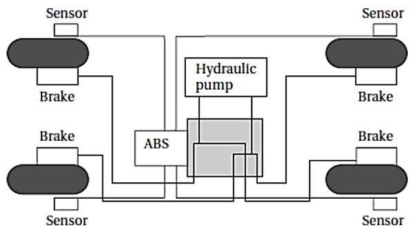
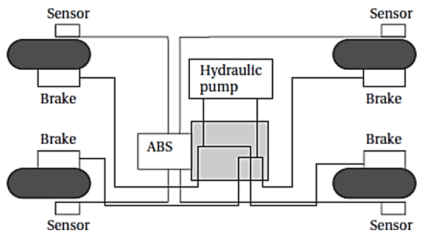
The BMW 850i was introduced with a sophisticated system for controlling the wheels of the car. An antilock brake system (ABS) reduces skidding by pumping the brakes. An automatic stability control (ASC_T) system intervenes with the engine during manoeuvring to improve the cars stability. These systems actively control critical systems of the car; as control systems, they require inputs from and output to the automobile. Lets first look at the ABS. The purpose of an ABS is to temporarily release the brake on a wheel when it rotates too slowly—when a wheel-stops turning, the car starts skidding and becomes hard to control. It sits between the hydraulic pump, which provides power to the brakes, and the brakes themselves as seen in the following diagram. This hook up allows the ABS system to modulate the brakes in order to keep the wheels from locking. The ABS system uses sensors on each wheel to measure the speed of the wheel.
The wheel speeds are used by the ABS system to determine how to vary the hydraulic fluid pressure to prevent the wheels from skidding. The ASC _ T systems job is to control the engine power and the brake to improve the cars stability during maneuvers. The ASC _ T controls four different systems: throttle, ignition timing, differential brake, and (on automatic transmission cars) gear shifting. The ASC_T can be turned off by the driver, which can be important when operating with tire snow chains. The ABS and ASC _ T must clearly communicate because the ASC _ T interacts with the brake system. Since the ABS was introduced several years earlier than the ASC _ T, it was important to be able to interface ASC _ T to the existing ABS module, as well as to other existing electronic modules. The engine and control management units include the electronically controlled throttle, digital engine management, and electronic transmission control. The ASC _ T control unit has two microprocessors on two printed circuit boards, one of which concentrates on logic-relevant components and the other on performance-specific components.
Key takeaway
The application areas and the products in the embedded domain are countless.
- Consumer Electronics: Camcorders, Cameras.
- Household appliances: Washing machine, Refrigerator.
- Automotive industry: Anti-lock braking system (ABS), engine control.
- Home automation & security systems: Air conditioners, sprinklers, fire alarms.
- Telecom: Cellular phones, telephone switches.
- Computer peripherals: Printers, scanners.
- Computer networking systems: Network routers and switches.
- Healthcare: EEG, ECG machines.
- Banking & Retail: Automatic teller machines, point of sales.
- Card Readers: Barcode, smart card readers.
This section provides an overview of the embedded system design process aimed at two objectives. First, it will give us an introduction to the various steps in embedded system design before we delve into them in more detail. Second, it will allow us to consider the design methodology itself. A design methodology is important for three reasons. First, it allows us to keep a scorecard on a design to ensure that we have done everything we need to do, such as optimizing performance or performing functional tests. Second, it allows us to develop computer-aided design tools.
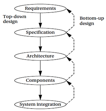
Developing a single program that takes in a concept for an embedded system and emits a completed design would be a daunting task, but by first breaking the process into manageable steps, we can work on automating (or at least semi automating) the steps one at a time. Third, a design methodology makes it much easier for members of a design team to communicate. By defining the overall process, team members can more easily understand what they are supposed to do, what they should receive from other team members at certain times, and what they are to hand off when they complete their assigned steps. Since most embedded systems are designed by teams, coordination is perhaps the most important role of a well-defined design methodology. Figure summarizes the major steps in the embedded system design process. In this top–down view, we start with the system requirements. In the next step
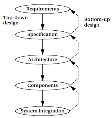
Specification, we create a more detailed description of what we want. But the specification states only how the system behaves, not how it is built. The details of the systems internals begin to take shape when we develop the architecture, which gives the system structure in terms of large components. Once we know the components we need, we can design those components, including both software modules and any specialized hardware we need. Based on those components, we can finally build a complete system.
In this section we will consider design from the top–down—we will begin with the most abstract description of the system and conclude with concrete details. The alternative is a bottom–up view in which we start with components to build a system. Bottom–up design steps are shown in the figure as dashed-line arrows. We need bottom–up design because we do not have perfect insight into how later stages of the design process will turn out. Decisions at one stage of design are based upon estimates of what will happen later: How fast can we make a particular function run? How much memory will we need? How much system bus capacity do we need? If our estimates are inadequate, we may have to backtrack and amend our original decisions to take the new facts into account. In general, the less experience we have with the design of similar systems, the more we will have to rely on bottom-up design information to help us refine the system. But the steps in the design process are only one axis along which we can view embedded system design. We also need to consider the major goals of the design:
- Manufacturing cost
- Performance (both overall speed and deadlines); and
- Power consumption.
Requirements analysis for big systems can be complex and time consuming. However, capturing a relatively small amount of information in a clear, simple format is a good start toward understanding system requirements. To introduce the discipline of requirements analysis as part of system design, we will use a simple requirements methodology. Figure shows a sample requirements form that can be filled out at the start of the project. We can use the form as a checklist in considering the basic characteristics of the system. Let‘s consider the entries in the form:
- Name: This is simple but helpful. Giving a name to the project not only simplifies talking about it to other people but can also crystallize the purpose of the machine.
- Purpose: This should be a brief one- or two-line description of what the system is supposed to do. If you can‘t describe the essence of your system in one or two lines, chances are that you don‘t understand it well enough.
- Inputs and outputs: These two entries are more complex than they seem. The inputs and outputs to the system encompass a wealth of detail: — Types of data: Analog electronic signals? Digital data? Mechanical inputs? — Data characteristics: Periodically arriving data, such as digital audio samples? Occasional user inputs? How many bits per data element? — Types of I/O devices: Buttons? Analog/digital converters? Video displays?
- Functions: This is a more detailed description of what the system does. A good way to approach this is to work from the inputs to the outputs: When the system receives an input, what does it do? How do user interface inputs affect these functions? How do different functions interact?
- Performance: Many embedded computing systems spend at least some time controlling physical devices or processing data coming from the physical world. In most of these cases, the computations must be performed within a certain time frame. It is essential that the performance requirements be identified early since they must be carefully measured during implementation to ensure that the system works properly.
- Manufacturing cost: This includes primarily the cost of the hardware components. Even if you don‘t know exactly how much you can afford to spend on system components, you should have some idea of the eventual cost range. Cost has a substantial influence on architecture: A machine that is meant to sell at $10 most likely has a very different internal structure than a $100 system.
- Power: Similarly, you may have only a rough idea of how much power the system can consume, but a little information can go a long way. Typically, the most important decision is whether the machine will be battery powered or plugged into the wall. Battery-powered machines must be much more careful about how they spend energy.
- Physical size and weight: You should give some indication of the physical size of the system to help guide certain architectural decisions. A desktop machine has much more flexibility in the components used than, for example, a lapel mounted voice recorder.
References:
1. M. A. Mazidi, J. G. Mazidi and R. D. McKinlay, “The8051Microcontroller and Embedded Systems: Using Assembly and C”, Pearson Education, 2007.
2. K. J. Ayala, “8051 Microcontroller”, Delmar Cengage Learning,2004.
3. The 8051 Microcontroller Based Embedded System by Manish K. Patel TMH.
4. Embedded System Architecture, Programming and Design by Raj Kamal, 3rd Edition TMH.
5. Introduction to Embedded System by Shibu K. V. 3rd Edition TMH
Unit - 4
Introduction to Embedded System
Unit - 4
Introduction to Embedded System
The Embedded System and the General-purpose computer are at two extremes. The embedded system is designed to perform a specific task whereas as per definition the general-purpose computer is meant for general use. It can be used for playing games, watching movies, creating software, work on documents or spreadsheets etc.
Following are certain specific points of difference between embedded systems and general-purpose computers:
- The first recognised embedded system is the Apollo Guidance Computer (AGC) developed by MIT lab.
- AGC was designed on 4K words of ROM & 256 words of RAM.
- The clock frequency of first microchip used in AGC was 1.024 MHz.
- The computing unit of AGC consists of 11 instructions and 16-bit word logic.
- It used 5000 ICs.
- The UI of AGC is known DSKY (display/keyboard) which resembles a calculator type keypad with array of numerals.
- The first mass-produced embedded system was guidance computer for the Minuteman-I missile in 1961.
- In the year 1971 Intel introduced the world's first microprocessor chip called the 4004, was designed for use in business calculators. It was produced by the Japanese company Busicom.
Embedded systems can be classified into different types based on performance, functional requirements and performance of the microcontroller.
Types of Embedded systems
Embedded systems are classified into four categories based on their performance and functional requirements:
- Stand alone embedded systems
- Real time embedded systems
- Networked embedded systems
- Mobile embedded systems
Embedded Systems are classified into three types based on the performance of the microcontroller such as
- Small scale embedded systems
- Medium scale embedded systems
- Sophisticated embedded systems
Stand Alone Embedded Systems
Stand alone embedded systems do not require a host system like a computer, it works by itself. It takes the input from the input ports either analog or digital and processes, calculates and converts the data and gives the resulting data through the connected device-Which either controls, drives and displays the connected devices. Examples for the stand alone embedded systems are mp3 players, digital cameras, video game consoles, microwave ovens and temperature measurement systems.
Real Time Embedded Systems
A real time embedded system is defined as, a system which gives a required o/p in a particular time. These types of embedded systems follow the time deadlines for completion of a task. Real time embedded systems are classified into two types such as soft and hard real time systems.
Networked Embedded Systems
These types of embedded systems are related to a network to access the resources. The connected network can be LAN, WAN or the internet. The connection can be any wired or wireless. This type of embedded system is the fastest growing area in embedded system applications. The embedded web server is a type of system wherein all embedded devices are connected to a web server and accessed and controlled by a web browser. Example for the LAN networked embedded system is a home security system wherein all sensors are connected and run on the protocol TCP/IP.
Mobile Embedded Systems
Mobile embedded systems are used in portable embedded devices like cell phones, mobiles, digital cameras, mp3 players and personal digital assistants, etc. The basic limitation of these devices is the other resources and limitation of memory.
Small Scale Embedded Systems
These types of embedded systems are designed with a single 8 or 16-bit microcontroller, that may even be activated by a battery. For developing embedded software for small scale embedded systems, the main programming tools are an editor, assembler, cross assembler and integrated development environment (IDE).
Medium Scale Embedded Systems
These types of embedded systems design with a single or 16 or 32 bit microcontroller, RISCs or DSPs. These types of embedded systems have both hardware and software complexities. For developing embedded software for medium scale embedded systems, the main programming tools are C, C++, JAVA, Visual C++, RTOS, debugger, source code engineering tool, simulator and IDE.
Sophisticated Embedded Systems
These types of embedded systems have enormous hardware and software complexities, that may need ASIPs, IPs, PLAs, scalable or configurable processors. They are used for cutting-edge applications that need hardware and software Co-design and components which have to assemble in the final system.
- C and C++ programming
- Microcontrollers, or MCUs
- Microprocessors
- Linux operating system
- Software optimizations skills at the System on a Chip (SoC) level
- Real-time Operating Systems (RTOS)
- Device drivers
- Understanding of design patterns and embedded system design patterns
- Debugging skills
- Ability to work with existing codebases
- Interrupt-driven design
- Assembly programming language
- Hardware test equipment: oscilloscope, logic analyser.
- Experience in or ability to learn communication protocols. Relevant protocols to have at least an understanding of include I2C, Serial Peripheral Interface (SPI), USB, General-purpose input/output (GPIOs), Controller Area Network (CAN bus), Recommended Standard 232 (RS232), one-wire, Recommended Standard 485 (RS485)
- Ability to read a schematic
- Basic understanding of Internet of Things (IoT) and internet-based technologies
- Understanding of data structures
- Python programming language
- RISC-V instruction set architecture
A Design Metric is a measurable feature of the system’s performance, cost, time for implementation and safety etc. Most of these are conflicting requirements i.e. optimizing one shall not optimize the other: e.g. a cheaper processor may have a lousy performance as far as speed and throughput is concerned. Following metrics are generally taken into account while designing embedded systems.
NRE cost (nonrecurring engineering cost)
It is one-time cost of designing the system. Once the system is designed, any number of units can be manufactured without incurring any additional design cost; hence the term nonrecurring. Suppose three technologies are available for use in a particular product. Assume that implementing the product using technology ‘A’ would result in an NRE cost of $2,000 and unit cost of $100, that technology B would have an NRE cost of $30,000 and unit cost of $30, and that technology C would have an NRE cost of $100,000 and unit cost of $2. Ignoring all other design metrics, like time-to-market, the best technology choice will depend on the number of units we plan to produce.
Unit cost
The monetary cost of manufacturing each copy of the system, excluding NRE cost.
Size
The physical space required by the system, often measured in bytes for software, and gates or transistors for hardware. Performance The execution time of the system
Power Consumption
It is the amount of power consumed by the system, which may determine the lifetime of a battery, or the cooling requirements of the IC, since more power means more heat.
Flexibility
The ability to change the functionality of the system without incurring heavy NRE cost. Software is typically considered very flexible.
Time-to-prototype
The time needed to build a working version of the system, which may be bigger or more expensive than the final system implementation, but it can be used to verify the system’s usefulness and correctness and to refine the system’s functionality.
Time-to-market
The time required to develop a system to the point that it can be released and sold to customers. The main contributors are design time, manufacturing time, and testing time. This metric has become especially demanding in recent years. Introducing an embedded system to the marketplace early can make a big difference in the system’s profitability.
Maintainability
It is the ability to modify the system after its initial release, especially by designers who did not originally design the system.
Correctness
This is the measure of the confidence that we have implemented the system’s functionality correctly. We can check the functionality throughout the process of designing the system, and we can insert test circuitry to check that manufacturing was correct.
An embedded system can be a computer hardware system having software embedded in it. An embedded system can be an independent system or it can be a part of a large system. An embedded system is a microcontroller or microprocessor-based system designed to perform a specific task.
For example, let us consider the fire alarm as an embedded system. This system only senses smoke.
An embedded system consists of three components −
- It has hardware.
- It has application software.
- It has a Real Time Operating system (RTOS) which defines the way the system works. It sets the rules during the execution of the application program. A small-scale embedded system may not have RTOS.
Characteristics of an Embedded System
- Single-functioned − An embedded system usually performs a specialized operation and does the same repeatedly. For example: A pager always functions as a pager.
- Tightly constrained − All computing systems have constraints on design metrics, but those on an embedded system can be especially tight. Design metrics is a measure of an implementation's features such as its cost, size, power, and performance
- Reactive and Real time − Many embedded systems must continually react to changes in the system's environment and must compute certain results in real time without any delay.
- Memory − It must have a memory, as its software usually embeds in ROM. It does not need any secondary memories in the computer.
- Connected − It must have connected peripherals to connect input and output devices.
- HW-SW systems − Software is used for more features and flexibility. Hardware is used for performance and security.
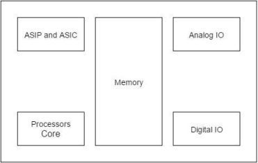
A processor has two essential units
- Program Flow Control Unit (CU)
- Execution Unit (EU)
The CU includes a fetch unit for fetching instructions from the memory. The EU has circuits that implement the instructions pertaining to data transfer operation and data conversion from one form to another.
The EU includes the Arithmetic and Logical Unit (ALU) and also the circuits that execute instructions for a program control task such as interrupt, or jump to another set of instructions. A processor runs the cycles of fetch and executes the instructions in the same sequence as they are fetched from memory.
Types of Processors
Processors can be of the following categories
- General Purpose Processor (GPP)
- Microprocessor o Microcontroller
- Embedded Processor
- Digital Signal Processor
- Media Processor
- Application Specific System Processor (ASSP)
- Application Specific Instruction Processors (ASIPs)
The Embedded system hardware includes elements like user interface, Input/Output interfaces, display and memory, etc. Generally an embedded system comprises power supply, processor, memory, timers, serial communication ports and system application specific circuits
The software embeds into hardware. Hardware consists of number of building blocks in a circuit board or in ASIC or on the SoC along with the processors. Hardware consists of following building blocks and devices in a system in general.
- Power Source: Various units in an embedded system operate in one of the ranges 5.0V±0,25 V. 3_3 V ±0.3V 2.0 V ±0,2 V and 1.5V± 0 2V.
- Clock Oscillator and Clocking Unit(s): The clock controls the time for executing an instruction, The frequency depends on the processor circuit execution rate.
- System Timer: A timer circuit is suitably configured and functions as system dock. The system clock ticks and generates system-interrupts periodically. The system-clock interrupt enables execution of the system supervisory functions in the OS at the periodic intervals. System clock ticks can be 60 times in second.
- Real-Time Clock (RTC): A real-time clock is required in a system. The clock drives the timers for various timing and counting needs in a system. The clock also updates time and date in the system. A microcontroller provides the timer circuits for the counting and tuning devices.
- Reset Circuit, Power-up Reset and Watchdog-Timer Reset A circuit for reset enables restart of the system from the beginning using a switch or signal. The reset can also be performed by using an instruction to the processor. A power-up reset circuit enables restart of the system from beginning whenever power is switched on in the system. A watchdog-timer reset enables the restart of system when it is stuck up in certain set of instructions for a period more than preset time-interval. Reset based on reset-switch, reset-instruction or power-up or power-up reset and watchdog reset can be from same starting instruction or the different starting instructions.
- Memory Various forms of memories are used in a system. Figure shows a chart for the various forms of memories that are present in systems. These are as follows:
- Internal RAM
- Internal ROM/PROM/EPROM
- External RAM for the temporary data and stack (in most systems)
- Internal caches (in pipelined and superscalar microprocessors)
- Internal EEPROM or flash (I) Memory Stick (card): video, images, songs, or speeches and large storage in digital camera, mobile systems
- External ROM or PROM for embedding soft are (in almost all other than microcontrollers-based systems)
- RAM Memory buffers at the ports
- Digital to Analog conversion (ADC): DAC is a circuit that converts digital 8, 10 r 12 bits to analog output. A DAC operation is done with the help of a combination of the Pulse Width Modulation (PWM) unit in a microcontroller and an external integrator chip.
- Analog to Digital Conversion (ADC): ADC is a circuit that converts the analog input to digital. The output is of 4, 8 10 or 12 bits from an ADC. Analog input is applied between + and – pins. ADC circuit converts them into bits. The converted bits value depends on the reference voltage. When input +ve and -ve pins are at voltage equal to reference +ve and -ve voltage pins, then all output bits = 1. When the difference in voltage at inputs +ve and -ve pins = 0v then all output bits = 0. An ADC unit in the embedded system microcontroller may have multi channels. It can then take the inputs in succession from the various interconnected to different analog sources.
- LED, LCD and Touch-Screen Displays: A system requires an interfacing circuit and software to display. LED is used for indicating ON status of the system. A flashing LED may indicate that, a specific task is under completion or is running. It may indicate a wait status for a message. The display may show the status or message. Display may be a line display, a multiline display or a flashing display. An LSI (Lower scale integrated circuit) is used as display controller in case of the LCD matrix display. Touch screen is an input as well as output device, which is used by the user of a system to enter a command, choose a menu or to give user reply as input. The input is on physical touch as a screen position. The touch at a position is mostly by the finger or some times by stylus. Stylus is a thin pencil shaped long object. It is held between the fingers and used just as a pen to mark a dot. An LSI (Lower scale integrated circuit) functions as touch-screen controller. The display-screen display is similar to a computer display unit screen
- Keypad, Keyboard or Virtual Keypad at touch screen: The keypad or keyboard, is an important device for getting user inputs. A touch screen provides virtual keypad in a mobile computing system. Virtual keypad is a keypad displayed on displayed on the LCD display screen on touch plate. A user can enter the inputs using touches. A tile is displayed for a command on the LCD display screen. User can enter the command using touch at the tile. A keypad or keyboard may interface to a system. The system may provide necessary interfacing circuit and software to receive inputs directly from the keys or touch screen controller
- Interrupt Handler: A system may process a number of devices. The system processor controls and handles the requirements of each device by running an appropriate ISR for each interrupting event, An interrupts-handling mechanism must exist in each system. It handles interrupts from various events or processors in the system. The system handled multiple interrupts, which may be simultaneously pending for service.
An embedded system processor and the system need software that is specific to a given application of that system. The processor of the system processes the instruction codes in data. In the final stage, these are placed in the memory ROM. For all the tasks that have been executed. The final state software is also called ROM Image. Each code or datum is available only in bits and bytes format. The system requires bits Each ram address, according to the task being executed. A machine implement able software file is there for like. Table of address and bits at. Each address of the system memory the table has to be read. Azar Ram image. For the targeted hardware. The figure below shows the ROM image. In our system memory. The image consists of the boot up program, commerce stack, address pointer, program counter, address pointer, application task, ISR, RTOS, input data, and vector addresses.
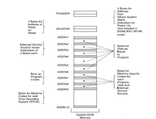
- ROM image
- Programming Languages
- Program models
ROM Image
- Final stage software also called ROM image
- Just as an image is a unique sequence and arrangement of
- Pixels, embedded software is also a unique placement and
- Arrangement at each ROM address of bytes for instructions and data
Final machine software
- Bytes at each address defined for creating the ROM image
- By changing this image, the same hardware platform work
- Differently and can be used for entirely different applications or
- For new upgrades of the same system.
- Hardware elements between the distinct systems can be identical but it is the software that makes a system unique and distinct from the other.
Compressed Codes and Data
ROM image may alternatively be compressed software (for example, the zip format) and data (for example, the pictures in jpg or gif format) along with the software required for decompression algorithm
Programming Languages
1. Machine Language Coding
- Programmer defines the addresses and the corresponding bytes or bits at each address
- Used in configuring some specific physical device or subsystem like transceiver, the machine code- based coding is used
2. Assembly Language Coding
- Needed for Invoking Processor Specific Instructions
- Requires understanding of the processor and instruction set
- A program or a small specific part coded in the assembly language using an Assembler (software used for developing codes in assembly).
Three steps when using assembly language
- 'Assembler',
- 'Linker' and
- 'Locator’
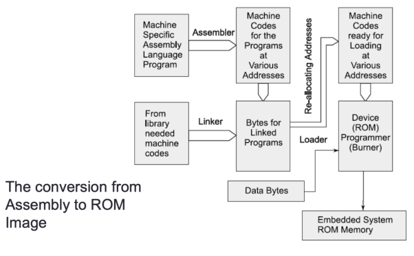
Before finally burned at the ROM
Program various layers
- Processor commands
- Main function
- Task functions and
- Library functions
- Interrupt service routines and kernel (scheduler)
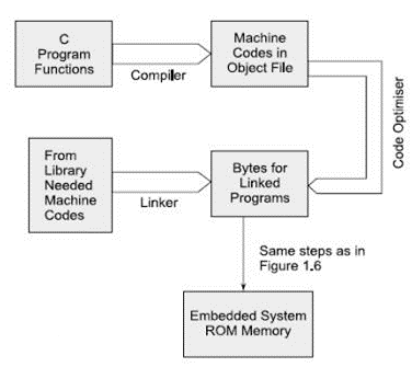
Compiler -Generates an object file. Using linker and locator, the file for ROM image is created for the targeted hardware. C++ and Java are other languages used for software coding.
Program Models
- Sequential Programming Model
- Object Oriented Programming Model
- Control and Data flow graphs or Synchronous Data Flow (SDF) Graph or Multi Thread Graph (MTG) Model
- Finite State Machine for data path
- Multithreaded Model
- Concurrent Processing of processes or thread or tasks
Embedded systems have very diversified application. A few select application areas of embedded systems are telecom, smart cards, missiles and satellites, Computer Networking, command digital consumers, electronics and automotive figure. Below shows embedded system.
- Automatic chocolate vending machine.
- Stepper motor controller for a robotic system washing or cooking system.
- Multitasking toys.
- Microcontroller based single or multi display digital panel meter for voltage pharma.
- Current, resistance and frequency.
- Keyboard controller
- Serial port cards.
- Computer mouse.
- CD driver hard drive controller.
- The peripheral controllers for a computer.
- For example, the CRT display controller keyboard controller. A disk drive controller.
- Fax or photocopy or printer or scanner machine.
- Digital diary.
- Remote of TV.
- Telephone with memory command display another sophisticated features.
- Motor control system.
- Electronic data acquisition supervisory control system.
- Electronic instruments such as an industrial process controller.
- Electronic smart weight display system, and industrial moisture record controller.
- Digital storage system for a single web of electric car wave water metre readings.
- Spectrum analyser. Biomedical system such as an ECG. LCD display come recorder.
- A blood cell recorder, communalise and patient monitor system.
CASE STUDY
BMW 850i brake and stability control system
The BMW 850i was introduced with a sophisticated system for controlling the wheels of the car. An antilock brake system (ABS) reduces skidding by pumping the brakes. An automatic stability control (ASC_T) system intervenes with the engine during manoeuvring to improve the cars stability. These systems actively control critical systems of the car; as control systems, they require inputs from and output to the automobile. Lets first look at the ABS. The purpose of an ABS is to temporarily release the brake on a wheel when it rotates too slowly—when a wheel-stops turning, the car starts skidding and becomes hard to control. It sits between the hydraulic pump, which provides power to the brakes, and the brakes themselves as seen in the following diagram. This hook up allows the ABS system to modulate the brakes in order to keep the wheels from locking. The ABS system uses sensors on each wheel to measure the speed of the wheel.
The wheel speeds are used by the ABS system to determine how to vary the hydraulic fluid pressure to prevent the wheels from skidding. The ASC _ T systems job is to control the engine power and the brake to improve the cars stability during maneuvers. The ASC _ T controls four different systems: throttle, ignition timing, differential brake, and (on automatic transmission cars) gear shifting. The ASC_T can be turned off by the driver, which can be important when operating with tire snow chains. The ABS and ASC _ T must clearly communicate because the ASC _ T interacts with the brake system. Since the ABS was introduced several years earlier than the ASC _ T, it was important to be able to interface ASC _ T to the existing ABS module, as well as to other existing electronic modules. The engine and control management units include the electronically controlled throttle, digital engine management, and electronic transmission control. The ASC _ T control unit has two microprocessors on two printed circuit boards, one of which concentrates on logic-relevant components and the other on performance-specific components.
Key takeaway
The application areas and the products in the embedded domain are countless.
- Consumer Electronics: Camcorders, Cameras.
- Household appliances: Washing machine, Refrigerator.
- Automotive industry: Anti-lock braking system (ABS), engine control.
- Home automation & security systems: Air conditioners, sprinklers, fire alarms.
- Telecom: Cellular phones, telephone switches.
- Computer peripherals: Printers, scanners.
- Computer networking systems: Network routers and switches.
- Healthcare: EEG, ECG machines.
- Banking & Retail: Automatic teller machines, point of sales.
- Card Readers: Barcode, smart card readers.
This section provides an overview of the embedded system design process aimed at two objectives. First, it will give us an introduction to the various steps in embedded system design before we delve into them in more detail. Second, it will allow us to consider the design methodology itself. A design methodology is important for three reasons. First, it allows us to keep a scorecard on a design to ensure that we have done everything we need to do, such as optimizing performance or performing functional tests. Second, it allows us to develop computer-aided design tools.
Developing a single program that takes in a concept for an embedded system and emits a completed design would be a daunting task, but by first breaking the process into manageable steps, we can work on automating (or at least semi automating) the steps one at a time. Third, a design methodology makes it much easier for members of a design team to communicate. By defining the overall process, team members can more easily understand what they are supposed to do, what they should receive from other team members at certain times, and what they are to hand off when they complete their assigned steps. Since most embedded systems are designed by teams, coordination is perhaps the most important role of a well-defined design methodology. Figure summarizes the major steps in the embedded system design process. In this top–down view, we start with the system requirements. In the next step
Specification, we create a more detailed description of what we want. But the specification states only how the system behaves, not how it is built. The details of the systems internals begin to take shape when we develop the architecture, which gives the system structure in terms of large components. Once we know the components we need, we can design those components, including both software modules and any specialized hardware we need. Based on those components, we can finally build a complete system.
In this section we will consider design from the top–down—we will begin with the most abstract description of the system and conclude with concrete details. The alternative is a bottom–up view in which we start with components to build a system. Bottom–up design steps are shown in the figure as dashed-line arrows. We need bottom–up design because we do not have perfect insight into how later stages of the design process will turn out. Decisions at one stage of design are based upon estimates of what will happen later: How fast can we make a particular function run? How much memory will we need? How much system bus capacity do we need? If our estimates are inadequate, we may have to backtrack and amend our original decisions to take the new facts into account. In general, the less experience we have with the design of similar systems, the more we will have to rely on bottom-up design information to help us refine the system. But the steps in the design process are only one axis along which we can view embedded system design. We also need to consider the major goals of the design:
- Manufacturing cost
- Performance (both overall speed and deadlines); and
- Power consumption.
Requirements analysis for big systems can be complex and time consuming. However, capturing a relatively small amount of information in a clear, simple format is a good start toward understanding system requirements. To introduce the discipline of requirements analysis as part of system design, we will use a simple requirements methodology. Figure shows a sample requirements form that can be filled out at the start of the project. We can use the form as a checklist in considering the basic characteristics of the system. Let‘s consider the entries in the form:
- Name: This is simple but helpful. Giving a name to the project not only simplifies talking about it to other people but can also crystallize the purpose of the machine.
- Purpose: This should be a brief one- or two-line description of what the system is supposed to do. If you can‘t describe the essence of your system in one or two lines, chances are that you don‘t understand it well enough.
- Inputs and outputs: These two entries are more complex than they seem. The inputs and outputs to the system encompass a wealth of detail: — Types of data: Analog electronic signals? Digital data? Mechanical inputs? — Data characteristics: Periodically arriving data, such as digital audio samples? Occasional user inputs? How many bits per data element? — Types of I/O devices: Buttons? Analog/digital converters? Video displays?
- Functions: This is a more detailed description of what the system does. A good way to approach this is to work from the inputs to the outputs: When the system receives an input, what does it do? How do user interface inputs affect these functions? How do different functions interact?
- Performance: Many embedded computing systems spend at least some time controlling physical devices or processing data coming from the physical world. In most of these cases, the computations must be performed within a certain time frame. It is essential that the performance requirements be identified early since they must be carefully measured during implementation to ensure that the system works properly.
- Manufacturing cost: This includes primarily the cost of the hardware components. Even if you don‘t know exactly how much you can afford to spend on system components, you should have some idea of the eventual cost range. Cost has a substantial influence on architecture: A machine that is meant to sell at $10 most likely has a very different internal structure than a $100 system.
- Power: Similarly, you may have only a rough idea of how much power the system can consume, but a little information can go a long way. Typically, the most important decision is whether the machine will be battery powered or plugged into the wall. Battery-powered machines must be much more careful about how they spend energy.
- Physical size and weight: You should give some indication of the physical size of the system to help guide certain architectural decisions. A desktop machine has much more flexibility in the components used than, for example, a lapel mounted voice recorder.
References:
1. M. A. Mazidi, J. G. Mazidi and R. D. McKinlay, “The8051Microcontroller and Embedded Systems: Using Assembly and C”, Pearson Education, 2007.
2. K. J. Ayala, “8051 Microcontroller”, Delmar Cengage Learning,2004.
3. The 8051 Microcontroller Based Embedded System by Manish K. Patel TMH.
4. Embedded System Architecture, Programming and Design by Raj Kamal, 3rd Edition TMH.
5. Introduction to Embedded System by Shibu K. V. 3rd Edition TMH