Unit - 1
Strings
Finite Automata(FA) is the simplest pattern recognition machine. The finite automatic or finite state machine is an abstract machine with five components or tuples. It has a set of states and rules that switch from one state to another, but it depends on the input symbol that is added. It is essentially an abstract digital machine model.
Some important features of general automation are shown in the figure below:
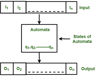
Fig 1: Features of finite automata
The figure above shows the following automated features:
● Input
● Output
● State of automata
● State relation
● Output relation
A Finite Automata consists of the following:
{Q, Σ, q, F, δ}.
Where,
Q: Finite set of states.
Σ: set of Input Symbols.
q: Initial state.
F: set of Final States.
δ: Transition Function.
Finite automata is divided into 2 types:
- Deterministic Finite Automaton (DFA)
In this, for each input symbol, the state to which the machine will move can be determined. As it has a finite number of states, the machine is called Deterministic Finite Machine or Deterministic Finite Automaton.
An automaton can be represented by a 5-tuple (Q, ∑, δ, q 0 , F),
Where −
Q is a finite set of states.
∑ is a finite set of symbols, called the alphabet of the automaton.
δ is the transition function.
q 0 is the initial state from where any input is processed (q 0 ∈ Q).
F is a set of final state/states of Q (F ⊆ Q).
2. Non-deterministic Finite Automaton (NDFA)
In NDFA, the machine can move to any combination of the states. Hence, it is called Non-deterministic Automaton as it has finite number of states.
Q → Finite non-empty set of states.
∑ → Finite non-empty set of input symbols.
∂ → Transitional Function.
q0 → Beginning state.
F → Final State
Basic terminology
Alphabet
● Definition − An alphabet is any finite set of symbols.
● Example − ∑ = {a, b, c, d} is an alphabet set where ‘a’, ‘b’, ‘c’, and ‘d’ are symbols.
String
● Definition − A string is a finite sequence of symbols taken from ∑.
● Example − ‘cabcad’ is a valid string on the alphabet set ∑ = {a, b, c, d}
Languages
● Definition − A language is a subset of ∑* for some alphabet ∑. It can be finite or infinite.
● Example − If the language takes all possible strings of length 2 over ∑ = {a, b}, then
L1 = {ab, aa, ba, bb} finite language
L2 = {a,aa,aaa,abb,abab} infinite language
Key takeaway:
Finite Automata(FA) is the simplest pattern recognition machine.
The finite automatic or finite state machine is an abstract machine with five components or tuples.
In DFA, for each input symbol, the state to which the machine will move can be determined.
In NDFA, the machine can move to any combination of the states.
Input tape and finite control can be used to represent finite automata.
Input tape: The input tape is a linear tape with a certain number of cells. Each cell contains an input symbol.
Finite control: When a certain input from an input tape is received, the finite control determines the next state. Only one input sign is received at a time by the tape reader, which reads the cells one by one from left to right.
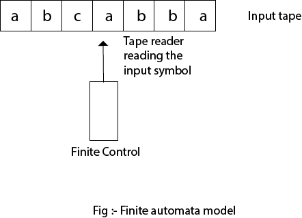
Fig 2: Finite automata model
Key takeaway
Input tape and finite control can be used to represent finite automata.
After reading the string entirely, a string is accepted by a DFA and the DFA, beginning at the initial state, ends in an accepting state (any of the final states).
A string S is accepted, if any, by the DFA (Q, ∑, δ, q0, F)
δ*(q0, S) ∈ F
The DFA-accepted language L is
{S | S ∈ ∑* and δ*(q0, S) ∈ F}
A DFA (Q, ∑ , δ, q0, F) does not accept a string S, if . .
δ*(q0, S′) ∉ F
The language L not recognised by the DFA/NDFA (Accepted language L complement) is .
{S | S ∈ ∑* and δ*(q0, S) ∉ F}
Example:
Let us take the DFA for consideration. The acceptable strings can be derived from the DFA.
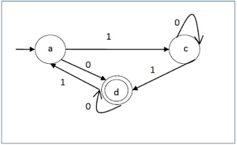
Fig 3: DFA example
Strings that are approved by the above DFA : {0, 00, 11, 010, 101, ...........}
Strings which were not approved by the above DFA : {1, 011, 111, ........}
In NDFA, the machine can move to any combination of the states. Hence, it is
Called Non-deterministic Automaton.
It has a finite number of states.
● Q → Finite non-empty set of states.
● ∑ → Finite non-empty set of input symbols.
● ∂ → Transitional Function.
● q0 → Beginning state.
● F → Final State
Transition function can be defined as:
δ: Q x ∑ →2Q
Graphical Representation of NFA
An NFA can be represented by digraphs called state diagram. In which:
- The state is represented by vertices.
- The arc labeled with an input character show the transitions.
- The initial state is marked with an arrow.
- The final state is denoted by the double circle.
Example
- Q = {q0, q1, q2}
- ∑ = {0, 1}
- q0 = {q0}
- F = {q2}
Solution:
Transition Diagram:

Transition table:
Present State | Next State for Input 0 | Next State of Input 1 |
→q0 | q0, q1 | q1 |
q1 | q2 | q0 |
*q2 | q2 | q1,q2 |
In this figure, we can see that the current state is q0(input 0), and the next state will be q0,q1(input 1) so the next state is q1. When the current state is q1(input 0), the next state will be q2(input 1), the next state is q0. When the current state is q2(input 0), the next state is q2( input 1), the next state will be q1 or q2.
In this, for each input symbol, the state to which the machine will move can be determined. As it has a finite number of states, the machine is called Deterministic Finite Machine or Deterministic Finite Automaton.
● An automaton can be represented by a 5-tuple (Q, ∑, δ, q 0 , F), where −
● Q is a finite set of states.
● ∑ is a finite set of symbols, called the alphabet of the automaton.
● δ is the transition function.
● q0 is the initial state from where any input is processed (q 0 ∈ Q).
● F is a set of final state/states of Q (F ⊆ Q).
Transition function can be defined as:
δ: Q x ∑→Q
Graphical Representation of DFA
A DFA can be represented by digraphs called state diagram. In which:
- The state is represented by vertices.
- The arc labeled with an input character shows the transitions.
- The initial state is marked with an arrow.
- The final state is denoted by a double circle.
Advantages and disadvantages
● DFAs are used to model a Turing machine.
● They are used as ++ models of computation.
● The union/intersection of the languages recognized by two given DFAs.
● The complement of the language recognized by a given DFA.
Example
Q = {q0, q1, q2}
∑ = {0,1}
q0 = {q0}
F = {q2}
Solution:
Transition Diagram:

Transition Table:
Present State | Next State for Input 0 | Next state of Input 1 |
→q0 | q0 | q1 |
q1 | q2 | q1 |
*q2 | q2 | q2 |
It would seem superficially that deterministic and non-deterministic finite state automata are totally distinct beasts. However, it turns out that they are equivalent. There is a DFA for every language recognized by an NFA that recognizes that language and vice versa.
The NFA to DFA conversion algorithm is relatively simple, even though the resulting DFA is substantially more complicated than the original NFA. I will illustrate this equivalence after the hop and also go through a brief example of converting an NFA to an equivalent DFA.
DFA and NFA Theorem proof -
Let's formally state the theorem we are proving before continuing:
Theorem:
Let the language L ⊆ Σ* be recognized by NFA N = (Σ, Q, q0, F, δ) and assume L.
A DFA D= (Σ, Q ', q'0, F', δ ') exists that also accepts L. (L(N)= L(D)).
We are able to prove by induction that D is equal to N by allowing each state in the DFA D to represent a set of states in the NFA N. Let's define the parameters of D: before we start proofing,
● Q’ is equal to the powerset of Q, Q’ = 2Q
● q’0 = {q0}
● F’ is the set of states in Q’ that contain any element of F, F’ = {q ∈ Q’|q ∩ F ≠ Ø}
● δ’ is the transition function for D. δ’(q,a) = Up∈ q δ(p, a)for q ∈ Q’ and a ∈ Σ
It's worth more explaining, I think δ '. Note that in the set of states Q 'in D, each state is a set of states from Q in N itself. Determine the transition δ (p,a) for each state p in state q in Q 'of D (p is a single state from Q). The union of all δ(q, a) is δ(q,a) .
Now we will demonstrate δ’(q0’, x) =δ’(q0 , x) that for every x i.e L(D) = L (N)
Step 1: Take ∈ closure for the beginning state of NFA as beginning state of DFA.
Step 2: Find the states that can be traversed from the present for each input symbol
(union of transition value and their closures for each states of NFA present in current state of DFA).
Step 3: If any new state is found take it as current state and repeat step 2.
Step 4: Do repeat Step 2 and Step 3 until no new state present in DFA transition table.
Step 5: Mark the states of DFA which contains final state of NFA as final states of DFA.
Transition state table for DFA corresponding to above NFA
States | 0 | 1 |
A,B,C | B,C | A,B,C |
B,C | C | B,C |
C | C | C |
DFA State diagram

● A Finite Automation has a finite number of states and is also called a Finite State Machine (FSM).
● FA(finite automata) is used for recognition patterns.
● FA have two states, Accept state or Reject state. When the input string is processed successfully, and the automata reaches its final state, then it will accept.
Moore Machine
The Moore machine is a finite state machine in which the current state and the current input symbol define the next state. At a given time, the output symbol depends only on the machine's current state.
Moore machine can be described by 6 tuples (Q, q0, ∑, O, δ, λ) where,
- Q: finite set of states
- q0: initial state of machine
- ∑: finite set of input symbols
- O: output alphabet
- δ: transition function where Q × ∑ → Q
- λ: output function where Q → O
Example:
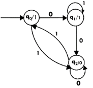
The state diagram for Moore Machine is-
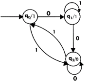
Transition Table for MM(moore machine) is
Current State | Next State(δ) | Output(λ) | |
0 | 1 | ||
q0 | q1 | q2 | 1 |
q1 | q2 | q1 | 1 |
q2 | q2 | q0 | 0 |
Mealy Machine
A Mealy Machine is a machine in which the output symbol depends on the machine's current input symbol and current state. The output is expressed in the Mealy machine with each input symbol for each state, separated by /.
The Mealy machine can be described by 6 tuples (Q, q0, ∑, O, δ, λ') where
- Q: finite set of states
- q0: initial state of machine
- ∑: finite set of input alphabet
- O: output alphabet
- δ: transition function where Q × ∑ → Q
- λ': output function where Q × ∑ →O
Equivalence of moore and merely
Moore and the mealy machine appear differently from each other.
Designing a moore machine with a mealy machine is often possible.
Designing a mealy machine with a moore machine is often possible.
It is possible to transform any Moore machine into a mealy machine.
Moore machine or mealy machine may be used to describe each standard language.
All languages specified by a mealy machine or moore machine are standard.

Fig 4: Example of equivalent moore and mealy machine
A moore machine M can never be correctly equal to a mealy machine M 'since one greater than that of the mealy machine M' on the same input is the length of the output string of a moore machine M.
We can, however, overlook the reaction of the moore machine to input λ and say
For all inputs w, moore machine M and a mealy machine M 'are equivalent if
Where b for its initial state is the output of the Moore machine M
Theorem: If M1= (Q, Σ, Δ, δ, λ ,q0 ) is a moore machine then there is an M2 equivalent to M1 mealy machine.
Proof: Create a mealy machine M2 as (Q, Σ, Δ, δ, λ’ ,q0 )
λ’ is describe as-
λ’(q,a) = λ(δ (q,a)) For q and input symbols of all states a
Moore machine is on input 1010 output
0 1 2 2 1
Although the output from the mealy machine constructed is
1 2 2 1
By the equivalence state
In the beginning of output of mealy machine, we can add output of q0 0 of moore machine
The machine generated is therefore equivalent to the Moore machine defined.
Key takeaway -
- In Finite automata there are a finite number of state , which is used for pattern recognition.
- FA (finite automata ) has a two state - Accept or Reject state
- In Moore machine the next state is determined by the present state and current input symbol.
- In Mealy machine the output is represented with each input symbol for each state, separated by /.
References:
- John E. Hopcroft, Rajeev Motwani, Jeffrey D.Ullman, “Introduction to Automata Theory Languages and Computation”, Addison-Wesley,ISBN 0-201-44124-1
- Sanjeev Arora and Boaz Barak, “Computational Complexity: A Modern Approach”,
- Cambridge University Press, ISBN: 0521424267 97805214242643
- John Martin, “Introduction to Languages and The Theory of Computation”, 2nd Edition, McGraw Hill Education, ISBN-13: 978-1-25-900558-9, ISBN-10: 1-25-900558-5
- J.Carroll & D Long, “Theory of Finite Automata”, Prentice Hall, ISBN 0-13-913708-45
Unit - 1
Strings
Finite Automata(FA) is the simplest pattern recognition machine. The finite automatic or finite state machine is an abstract machine with five components or tuples. It has a set of states and rules that switch from one state to another, but it depends on the input symbol that is added. It is essentially an abstract digital machine model.
Some important features of general automation are shown in the figure below:
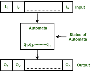
Fig 1: Features of finite automata
The figure above shows the following automated features:
● Input
● Output
● State of automata
● State relation
● Output relation
A Finite Automata consists of the following:
{Q, Σ, q, F, δ}.
Where,
Q: Finite set of states.
Σ: set of Input Symbols.
q: Initial state.
F: set of Final States.
δ: Transition Function.
Finite automata is divided into 2 types:
- Deterministic Finite Automaton (DFA)
In this, for each input symbol, the state to which the machine will move can be determined. As it has a finite number of states, the machine is called Deterministic Finite Machine or Deterministic Finite Automaton.
An automaton can be represented by a 5-tuple (Q, ∑, δ, q 0 , F),
Where −
Q is a finite set of states.
∑ is a finite set of symbols, called the alphabet of the automaton.
δ is the transition function.
q 0 is the initial state from where any input is processed (q 0 ∈ Q).
F is a set of final state/states of Q (F ⊆ Q).
2. Non-deterministic Finite Automaton (NDFA)
In NDFA, the machine can move to any combination of the states. Hence, it is called Non-deterministic Automaton as it has finite number of states.
Q → Finite non-empty set of states.
∑ → Finite non-empty set of input symbols.
∂ → Transitional Function.
q0 → Beginning state.
F → Final State
Basic terminology
Alphabet
● Definition − An alphabet is any finite set of symbols.
● Example − ∑ = {a, b, c, d} is an alphabet set where ‘a’, ‘b’, ‘c’, and ‘d’ are symbols.
String
● Definition − A string is a finite sequence of symbols taken from ∑.
● Example − ‘cabcad’ is a valid string on the alphabet set ∑ = {a, b, c, d}
Languages
● Definition − A language is a subset of ∑* for some alphabet ∑. It can be finite or infinite.
● Example − If the language takes all possible strings of length 2 over ∑ = {a, b}, then
L1 = {ab, aa, ba, bb} finite language
L2 = {a,aa,aaa,abb,abab} infinite language
Key takeaway:
Finite Automata(FA) is the simplest pattern recognition machine.
The finite automatic or finite state machine is an abstract machine with five components or tuples.
In DFA, for each input symbol, the state to which the machine will move can be determined.
In NDFA, the machine can move to any combination of the states.
Input tape and finite control can be used to represent finite automata.
Input tape: The input tape is a linear tape with a certain number of cells. Each cell contains an input symbol.
Finite control: When a certain input from an input tape is received, the finite control determines the next state. Only one input sign is received at a time by the tape reader, which reads the cells one by one from left to right.
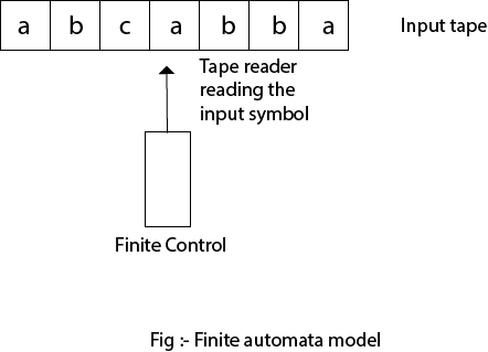
Fig 2: Finite automata model
Key takeaway
Input tape and finite control can be used to represent finite automata.
After reading the string entirely, a string is accepted by a DFA and the DFA, beginning at the initial state, ends in an accepting state (any of the final states).
A string S is accepted, if any, by the DFA (Q, ∑, δ, q0, F)
δ*(q0, S) ∈ F
The DFA-accepted language L is
{S | S ∈ ∑* and δ*(q0, S) ∈ F}
A DFA (Q, ∑ , δ, q0, F) does not accept a string S, if . .
δ*(q0, S′) ∉ F
The language L not recognised by the DFA/NDFA (Accepted language L complement) is .
{S | S ∈ ∑* and δ*(q0, S) ∉ F}
Example:
Let us take the DFA for consideration. The acceptable strings can be derived from the DFA.
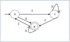
Fig 3: DFA example
Strings that are approved by the above DFA : {0, 00, 11, 010, 101, ...........}
Strings which were not approved by the above DFA : {1, 011, 111, ........}
In NDFA, the machine can move to any combination of the states. Hence, it is
Called Non-deterministic Automaton.
It has a finite number of states.
● Q → Finite non-empty set of states.
● ∑ → Finite non-empty set of input symbols.
● ∂ → Transitional Function.
● q0 → Beginning state.
● F → Final State
Transition function can be defined as:
δ: Q x ∑ →2Q
Graphical Representation of NFA
An NFA can be represented by digraphs called state diagram. In which:
- The state is represented by vertices.
- The arc labeled with an input character show the transitions.
- The initial state is marked with an arrow.
- The final state is denoted by the double circle.
Example
- Q = {q0, q1, q2}
- ∑ = {0, 1}
- q0 = {q0}
- F = {q2}
Solution:
Transition Diagram:

Transition table:
Present State | Next State for Input 0 | Next State of Input 1 |
→q0 | q0, q1 | q1 |
q1 | q2 | q0 |
*q2 | q2 | q1,q2 |
In this figure, we can see that the current state is q0(input 0), and the next state will be q0,q1(input 1) so the next state is q1. When the current state is q1(input 0), the next state will be q2(input 1), the next state is q0. When the current state is q2(input 0), the next state is q2( input 1), the next state will be q1 or q2.
In this, for each input symbol, the state to which the machine will move can be determined. As it has a finite number of states, the machine is called Deterministic Finite Machine or Deterministic Finite Automaton.
● An automaton can be represented by a 5-tuple (Q, ∑, δ, q 0 , F), where −
● Q is a finite set of states.
● ∑ is a finite set of symbols, called the alphabet of the automaton.
● δ is the transition function.
● q0 is the initial state from where any input is processed (q 0 ∈ Q).
● F is a set of final state/states of Q (F ⊆ Q).
Transition function can be defined as:
δ: Q x ∑→Q
Graphical Representation of DFA
A DFA can be represented by digraphs called state diagram. In which:
- The state is represented by vertices.
- The arc labeled with an input character shows the transitions.
- The initial state is marked with an arrow.
- The final state is denoted by a double circle.
Advantages and disadvantages
● DFAs are used to model a Turing machine.
● They are used as ++ models of computation.
● The union/intersection of the languages recognized by two given DFAs.
● The complement of the language recognized by a given DFA.
Example
Q = {q0, q1, q2}
∑ = {0,1}
q0 = {q0}
F = {q2}
Solution:
Transition Diagram:

Transition Table:
Present State | Next State for Input 0 | Next state of Input 1 |
→q0 | q0 | q1 |
q1 | q2 | q1 |
*q2 | q2 | q2 |
It would seem superficially that deterministic and non-deterministic finite state automata are totally distinct beasts. However, it turns out that they are equivalent. There is a DFA for every language recognized by an NFA that recognizes that language and vice versa.
The NFA to DFA conversion algorithm is relatively simple, even though the resulting DFA is substantially more complicated than the original NFA. I will illustrate this equivalence after the hop and also go through a brief example of converting an NFA to an equivalent DFA.
DFA and NFA Theorem proof -
Let's formally state the theorem we are proving before continuing:
Theorem:
Let the language L ⊆ Σ* be recognized by NFA N = (Σ, Q, q0, F, δ) and assume L.
A DFA D= (Σ, Q ', q'0, F', δ ') exists that also accepts L. (L(N)= L(D)).
We are able to prove by induction that D is equal to N by allowing each state in the DFA D to represent a set of states in the NFA N. Let's define the parameters of D: before we start proofing,
● Q’ is equal to the powerset of Q, Q’ = 2Q
● q’0 = {q0}
● F’ is the set of states in Q’ that contain any element of F, F’ = {q ∈ Q’|q ∩ F ≠ Ø}
● δ’ is the transition function for D. δ’(q,a) = Up∈ q δ(p, a)for q ∈ Q’ and a ∈ Σ
It's worth more explaining, I think δ '. Note that in the set of states Q 'in D, each state is a set of states from Q in N itself. Determine the transition δ (p,a) for each state p in state q in Q 'of D (p is a single state from Q). The union of all δ(q, a) is δ(q,a) .
Now we will demonstrate δ’(q0’, x) =δ’(q0 , x) that for every x i.e L(D) = L (N)
Step 1: Take ∈ closure for the beginning state of NFA as beginning state of DFA.
Step 2: Find the states that can be traversed from the present for each input symbol
(union of transition value and their closures for each states of NFA present in current state of DFA).
Step 3: If any new state is found take it as current state and repeat step 2.
Step 4: Do repeat Step 2 and Step 3 until no new state present in DFA transition table.
Step 5: Mark the states of DFA which contains final state of NFA as final states of DFA.
Transition state table for DFA corresponding to above NFA
States | 0 | 1 |
A,B,C | B,C | A,B,C |
B,C | C | B,C |
C | C | C |
DFA State diagram

● A Finite Automation has a finite number of states and is also called a Finite State Machine (FSM).
● FA(finite automata) is used for recognition patterns.
● FA have two states, Accept state or Reject state. When the input string is processed successfully, and the automata reaches its final state, then it will accept.
Moore Machine
The Moore machine is a finite state machine in which the current state and the current input symbol define the next state. At a given time, the output symbol depends only on the machine's current state.
Moore machine can be described by 6 tuples (Q, q0, ∑, O, δ, λ) where,
- Q: finite set of states
- q0: initial state of machine
- ∑: finite set of input symbols
- O: output alphabet
- δ: transition function where Q × ∑ → Q
- λ: output function where Q → O
Example:
The state diagram for Moore Machine is-
Transition Table for MM(moore machine) is
Current State | Next State(δ) | Output(λ) | |
0 | 1 | ||
q0 | q1 | q2 | 1 |
q1 | q2 | q1 | 1 |
q2 | q2 | q0 | 0 |
Mealy Machine
A Mealy Machine is a machine in which the output symbol depends on the machine's current input symbol and current state. The output is expressed in the Mealy machine with each input symbol for each state, separated by /.
The Mealy machine can be described by 6 tuples (Q, q0, ∑, O, δ, λ') where
- Q: finite set of states
- q0: initial state of machine
- ∑: finite set of input alphabet
- O: output alphabet
- δ: transition function where Q × ∑ → Q
- λ': output function where Q × ∑ →O
Equivalence of moore and merely
Moore and the mealy machine appear differently from each other.
Designing a moore machine with a mealy machine is often possible.
Designing a mealy machine with a moore machine is often possible.
It is possible to transform any Moore machine into a mealy machine.
Moore machine or mealy machine may be used to describe each standard language.
All languages specified by a mealy machine or moore machine are standard.

Fig 4: Example of equivalent moore and mealy machine
A moore machine M can never be correctly equal to a mealy machine M 'since one greater than that of the mealy machine M' on the same input is the length of the output string of a moore machine M.
We can, however, overlook the reaction of the moore machine to input λ and say
For all inputs w, moore machine M and a mealy machine M 'are equivalent if
Where b for its initial state is the output of the Moore machine M
Theorem: If M1= (Q, Σ, Δ, δ, λ ,q0 ) is a moore machine then there is an M2 equivalent to M1 mealy machine.
Proof: Create a mealy machine M2 as (Q, Σ, Δ, δ, λ’ ,q0 )
λ’ is describe as-
λ’(q,a) = λ(δ (q,a)) For q and input symbols of all states a
Moore machine is on input 1010 output
0 1 2 2 1
Although the output from the mealy machine constructed is
1 2 2 1
By the equivalence state
In the beginning of output of mealy machine, we can add output of q0 0 of moore machine
The machine generated is therefore equivalent to the Moore machine defined.
Key takeaway -
- In Finite automata there are a finite number of state , which is used for pattern recognition.
- FA (finite automata ) has a two state - Accept or Reject state
- In Moore machine the next state is determined by the present state and current input symbol.
- In Mealy machine the output is represented with each input symbol for each state, separated by /.
References:
- John E. Hopcroft, Rajeev Motwani, Jeffrey D.Ullman, “Introduction to Automata Theory Languages and Computation”, Addison-Wesley,ISBN 0-201-44124-1
- Sanjeev Arora and Boaz Barak, “Computational Complexity: A Modern Approach”,
- Cambridge University Press, ISBN: 0521424267 97805214242643
- John Martin, “Introduction to Languages and The Theory of Computation”, 2nd Edition, McGraw Hill Education, ISBN-13: 978-1-25-900558-9, ISBN-10: 1-25-900558-5
- J.Carroll & D Long, “Theory of Finite Automata”, Prentice Hall, ISBN 0-13-913708-45