Unit 4
Basic Electrical
I Ø transformers and electrostatics
- Types of transformers
Acc to input supply : I phase and  phase
phase
Acc to construction : core and shell type
Acc to 0/P : step up and step down
Construction of transformers (study only for MCQs)
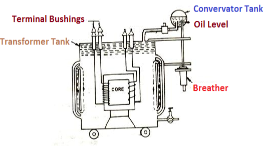
- Laminated steel core
Material used for core is (silicon steel) it is used for its (high permeability) and (low magnetic reluctance)  magnetic field produced is very strong
The core is formed of (stacks of laminated thin steel sheets) which are electrically isolated from each other. They are typically (0.35 to 0.5 mm thick)
We can used 2 ‘L’ shaped sheets or 2  shaped sheets for laminations
Construction and types
- There a 2 types of winding
- Concentric or cylindrical
- Sandwiched type
- Cylindrical
L.V. = low voltage H.V. = high voltage are mounted on same limb to minimum leakage .
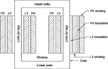
L.V. Winding placed inside and H.V. Winding placed outside with (proper insulation between the winding as it is easy to insulated L.V. Winding) than H.V. Winding.
2. Sandwiched
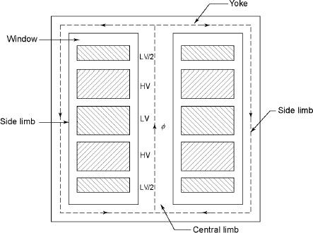
The H.V. And L.V. Winding are divided into no. Of small coils and there small windings are interleaved.
(the top and bottom winding are L.V. Coils because they are close to core)
- Transformer tank : wholes assembly of winding and core placed inside the Transformer tank (sheet metal tank) which is filled with Transformer oil or insulating oil which acts as an (insulator or coolant ) MCQ
- Transformer oil : (The function of oil is to remove efficiently the heat generated in core and in winding)
- Moisture should not be allowed which creeps the insulation which achieved by closed Transformer tank.
(To increase cooling surface are tubes or fins are provided)
- Conservator tank : above tank T/F tank there is one small tank in which same empty space is always provided above the oil level. (this space is required for oil to expand or contract due to temperature change) MCQ
However during contraction outside air can have moisture which will deteriorate the insulating properly of oil.
- Breather : the air goes in or out through the breather (To reduce the moisture content of their air . Same drying agents such as (silica gel or) calcium chloride) is used in the breather (The dust particles present in air are also removed by breather)
- Buccholz Relay : (for incipient (slowly increasing) faults
There is pipe connecting rain tank and conservator. On the pipe a protective device called Buccholz Relay is mounted.
When the Transformer is about to be faulty and draw range current the oil becomes very hot and decompose.
During this process different types of gases are liberated.(The Bucchoz Relay get operated by these gases) and gives an alarm to the operator. ɡȴ the fault continues to persist then there lay will trip off main circuit breaker to protect the Transformer.
- Explosion Vent :
An explosion Vent or relief value is the bent up pipe filled on the main tank.
(The explosion vent consist of aluminium of oil ) when the T/F becomes faulty the cooling oil get decomposed and various types of gases are liberated
(ɡȴ the gas pressure exodus certain level then the aluminium of oil (diagram) in explosion vent will burst) to release pressure. The will save main tank from getting damaged.
- Single phase transformer - for MCQs
(Symbol and principal of operation)
It is a static device which can transfer electrical energy from one ac circuit to another ac circuit without change in frequency
It can increase or decrease the voltage but with corresponding decrease or increase in current
It works on Principle 
“Mutual Induction”
A major application of transformer is to increase voltage before transmitting electrical energy over a long distance through conductors and to again reduce voltage at place where it is to be used.
Symbol
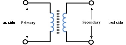
- Primary winding : (ac supply side) For MCQs
The winding which is connected to supply is called primary side
2. Secondary winding : (load side) for MCQs
The winding which is connected to load is called as secondary winding
- Working : For MCQs
It works on principle of mutual Induction ie “when 2 coil are inductively coupled and if current in one coil is changed uniformly then an emf get induced in another coil”
- When alternating voltage V1 is applied to primary winding am alternating current I1 flows in it producing alternating flux in the core.
- As per Faradays Law of Electromagnetic Induction 1 an emf E1 is induced in the primary winding E = N1

- The emf induced in the primary winding is nearly equal and opporite to applied voltage V1
- Assuming leakage flux to be negligible almost whole flux produced in primary winding links with secondary winding thence emf induced in the secondary winding E2 = N2

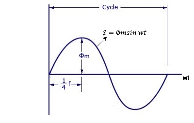
As primary winding excited by the a sinusoidal alternating voltage an alternating current flows in the winding producing an alternating varying flux Ø
Ø = Øm sin wt
As per Faradays Law of Electromagnetic Induction emf E1 is induced
E1 = N1
E1 = N1 (Ø Sin wt)
= - N1Øm w Cos wt
Sin (90-wt)
= - Sin (wt-90)
 E1 = N1Øm w Sin (wt-90)
 w =
w = 
 E1 =
E1 =  N1 Ø m Sin (wt-90)
Max value of E1 = E max
Is when Sin (wt-90) =  1
1
E1 max =  N1 Ø m
Hence rms value of induced EMF in primary winding
E1 rms =  =
= 
 E1 = 4.44 F Ø m N1
 Similarly RMS value of induced EMF in secondary wdg Is
E2 = 4.44 F Ø m N2
As total transformer loss ( loss +Cu loss)
Depends on VA and has no relation with phase angle between voltage and currents . But  loss depends on current and iron loss on voltage , hence, rating is always KVA.
Que A 10000/ 250 v , 120KVA 1- Transformer 50 h z supply .has core loss of 1.2 KW nas F.L
  loss of 1.8 KW . Find (2) KVA load for max efficiency and value of max. Frequency at unity P.F (2) the efficiency at half F.L 0.8 PF lagging?
Solution : (1) load KVA for max efficiency
= F.L KVA *  = 120 *
  =
=
= 97.98KVA
At  cu loss = Iron loss
Total Loss = 1.2+1.2 = 2.4kw
Output = 97.98*1 = 97.98kw
 =
=  =1.59%
2) cu Loss at half full load =1.8*( )2=0.45kw
Total loss =1.2+0.45=1.65kw
Half F.L output at 0.8 pf = *0.8= 48 kw
n= = 0.97
When an actual transformer is put on load we get losses (iron loss) in core and (copper loss) in primary and secondary windings. In NO LOAD (primary current is not purely reactive) the input current has to supply iron loss to core and small amount of copper loss in primary.
The no-load power is W0 = V1 I0 cos Φ0
I0 – no load primary input current
Cos Φ0 – power factor at no-load condition
I0 lags V1 by Φ0< 900
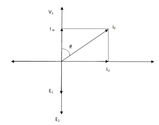
The phasor is shown below.
Phasor for No-Load Transformer
From above figure we can conclude that I0 has two components Iw(in phase with V1) Iµ in quadrature with V1
Iw = I0ws φ0( iron loss component )
Iµ = I0 cos φ0( magnetising component )
I0 = I2µ + I2w
The no-load primary current I0 is very small as compared to full-load primary current. And hence, no-load cu loss is very small. So, primary input is practically equal to iron loss of transformer.
Q1>. A 2500/200 V transformer draws a no-load primary current of 0.5 A and absorbs 400 W. Find magnetising and loss currents.
Sol: Iron-loss current = No load input(W) / Primary voltage
= 400/2500 = 0.16 A
I20 = I2w + I2µ
Iµ = √I20 – I2w
= √(0.5)2 – (0.16)2
Iµ = 0.473 A
Q2>. A 1-φ transformer has 1000 turns on primary and 200 on secondary. The no load current is 4 amp at p.f of 0.2 lagging. Find primary current and pf when secondary current is 280 A at pf of 0.6 lagging.
Sol : cos-1 0.6 = 53.130 (sin φ = 0.8)
I2 = 280/-53.130A
Φ = cos-1 0.2 = 78.50
Sin φ = 0.98
I1 = I0 + I’2
I’2 = (I2/K) ( -53.130
K = N1/N2 = 1000/200 = 5
I’2 = 280/5 (-53.130
I’2 = 56(-53.130
I1 = I0 + I’2
= 4(0.20 – j0.98) + 56(0.6 – j0.8)
= 0.80 – j3.92 + 33.6 – j44.8
I1 = 34.4 – j48.72
I1 = 59.64 ( -54.770
I lags supply voltage by 54.770
Transformer on load:
When secondary winding is loaded then the current in it is setup(IQ). The current I2 is in phase with V2 if load is non-inductive it lags if load is inductive & leads if load is capacitive.
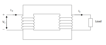
An mmf is set up at secondary and hence φ2 flux is induced which is in opposition to main flux φ due to I0. The flux φ2 weaken φ and hence primary back emf E1 is reduced. An additional primary current I’2 is introduced exactly at instance when I2 is introduced. So, that magnetic effect of I2 is neutralized by I’2.
Φ2 = φ’2
N2 I2 = N1 I’2
I’2 = N2/N1 x I2 = K2 I2
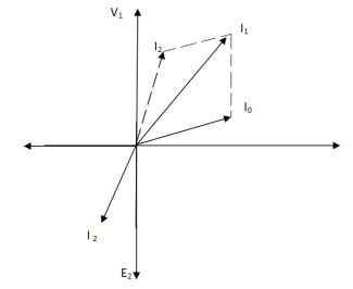
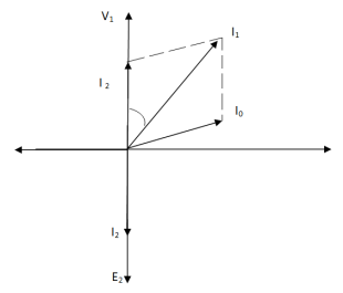
The phasor is shown below,
(a) (b)
Fig. Phasor for Load Transformer
From fig (a) (non – inductive load)
I2 is in phase with E2(=V2)
I’2 is antiphase with but equal in magnitude
I1 is vector sum of I’2 and I0, but lags V1
From fig (b), Inductive load
I2 lags V2
I’2 is not in phase with I2 but equal in magnitude
I1 is vector sum of I’2& I0 but lags V1
I’2/I2 = I1/I2 = N2/N1 = K
Q>. A 1- φ transformer with ratio of 440/110-V takes a no-load current of 6 A at 0.3 pf lagging. If secondary supplies 120 A at pf of 0.8 lagging. Find current taken by primary.
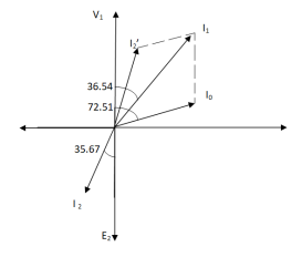
Sol>.
Cos φ2 = 0.8
Φ2 = 36.540
Cos φ0 = 0.3
Φ0 = 72.540
K = V2/V1 = 110/440 = ¼
I’2 = KI2 = 120 x ¼ = 30 A
I0 = 6A
Angle between I0& I’2
= 72.54 – 36.54
= 35.670
From vector diagram,
I1 = √(62 + 302 + 2 x 6 x 30 cos 35.67)
I1 = 35.05 A
Leakage Flux:
The flux linked with primary does not links with the secondary. Some part of the flux completes its magnetic circuit by passing through air, rather than core. This is known as primary leakage flux.
Fig. Leakage flux in Transformer
From above figure we can conclude that
(i). Leakage flux produced in primary exists between a and b. The flux φL1 is in phase with I1.
(ii). φL1 induces and emf eL1 in primary and not in secondary windings.
(iii). Leakage flux in secondary is produced between c and d. The flux φL2 is in phase with I2 and produces induced emf eL2 in secondary only.
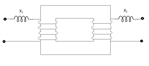
We can also say that a transformer with magnetic leakage is equivalent to an ideal transformer with inductive coils connected in both primary and secondary circuits.
X1 = eL1/I1 , X2 = eL2/I2
X1 – Primary leakage reactance
X2 – Secondary leakage reactance
- Losses in a Transformer [6m]
There are 2 types of losses occurring in a transformer
A) 1. Core loss or Iron loss
B) 2. Copper loss
- Core losses:
- This loss is due to the reversal of flux
- The flux set up in the core is dependent on the i/p supply
 as the i/p supply is constant in magnitude
  the flux set up will be constant and
  core losses are also constant.
 - Core losses are voltage dependent loss they can be subdivided in 2
1 Hysteresis loss
2 reedy current loss
- Hysteresis loss : The iron loss occurring in the core of T/F due to the Hysteresis curve of the magnetic material used for core is called as Hysteresis loss.
Hysteresis curve is the curve as loop which shows the properly of magnetic material to lag the flux density B behind the field Intensely H
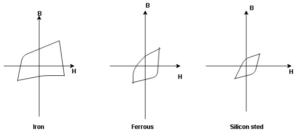
Above is the 3 different loops (Hysteresis of 3 diff. Materials)
 the selection of magnetic material for the construction of core depends upon Hysteresis loop of that material having tall and narrow Hysteresis loop is selected for the T/F core
 silicon Steel
Hysteresis loss depends on fold factor
PH = KH. Bm1.67 F  V – watts
Where KH = constant (Hyst)
Bm = max Flux density
F = Frequency
 = Volume of core.
2. Reedy current loss :
This loss is due to the flow of reedy (circular) current in the core caused by induced emf in core
PE = Ke Bm2 f2 t2 v – watts
Where
Ke = reedy current const.
t = thickness of core
It can be reduced by using stacks of laminations instead of solid core
B] Copper loss : PCU
The Copper loss is due to resistance of the primary and secondary winding
It is load dependent / current dependent loss
As load on a transformer is variable (changing)  current changes
  copper loss is a variable loss
Primary secondary
Total C is loss = I12 R12 + I22 R22
Copper loss depends upon load on T/F and is proportional to square of load current or KVA rating of transformer
 PCU
PCU  2
2 (KVA)2
F.L = full load
 PCU (at half load) =
  2 PCu F.L
= (0.5)2 PCU F.L.
Or PCu ( load) = (
 )2 PCu F.L
Vat ampere rating / rating of transformer for MCQs
As the rating decides the O/P power of any machine and the o/p power depends upon the efficiency of that machine which depends upon losses of the machine
- As the transformer losses depends on voltage and current, the rating of transformer is specified as the product of voltage and current called as V I rating / VA rating
- The rating of T/F indicates the output power from it but transformer load is not fixed
Hence rating of transformer is not expressed in terms of power but in terms of product of voltage and current called as VA rating
The rating is expressed as KVA rating
 rating of T/F KVA =
  =
= 
 full load primary current
 1 =
1 = 
Full load secondary current
 2 =
2 =  for MCQs numerical
Efficiency : it is the ratio output power to input power of transformer
 =
= 
Output power = input power – total loss
 Input power = O/P + losses

O/P power = KVA  Cos Ø2
  1000
1000
Or = V2  I2 Cos Ø2
Losses = Pi + PCU (F.L)
= iron + copper loss
 Full load =
 Half load(H.L) or 50% or 0.5 =

 =
= 
Maximum efficiency – for numerical :
The efficiency of T/F is maximum when copper loss equates iron loss this is the condition for max efficiency
Ie Pi = PCU
 =
= 
 PCU = Pi at max n
Where KVA at max n given = Full load KVA 
Voltage regulation: (for MCQs numerical)
The change in secondary terminal voltage from no load to full load condition expressed as fraction of no load secondary voltage is called as voltage regulation
 regulation =

OPEN CIRCUIT TEST :
Basically these tests are performed to find the basic parameters of transformers. The open circuit test is performed to determine no-load loss(core loss) and no-load current I0 which is helpful in finding X0 and R0.
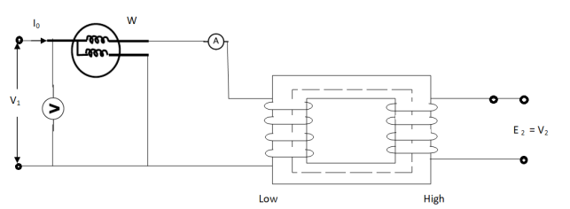
Fig. Open Circuit Test
In this test the high voltage winding is left open and the other is connected to supply.
A wattmeter W, voltmeter V and an Ammeter A are connected to L.V. Winding.
Due to applied voltage in primary, flux is set up in core, and hence normal iron loss occurs. This is recorded in Wattmeter. The current I0 is measured by Ammeter A.
Wattmeter reading represents core loss under no-load condition.
The wattmeter reading will be given as
W = V1 I0 cos φ0
Iµ = I0 Sin φ0
Iw = I0 cos φ0
X0 = V1/Iµ, R0 = V1/Iw
At no load I0 ≈ Iµ
I0 = V1 Y0
Y0 – Exciting Admittance
W = V21 G0
G0 – Exciting conductance
B0 = √ Y20 – G20
B0 – Exciting susceptance
(2). SHORT CIRCUIT TEST :
This test is used to determine
(i). Equivalent Impedance (Z01, Z02), leakage reactances (X01 or X02), Total resistance (R01, R02).
(ii). Cu losses are also calculated at full load.
(iii). The regulation of transformer can be determined as Z01, Z02 can be calculated.
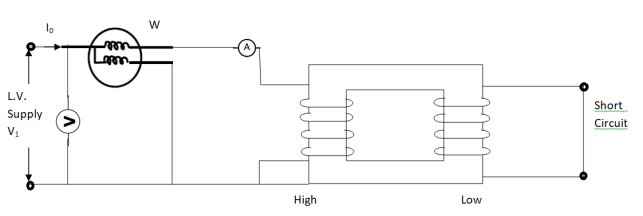
Here low voltage is short circuited. And the supply is through high voltage (primary here).
As applied voltage is small, hence the flux φ induced is also small.
As core losses are very small, the wattmeter reading is the cu-loss at full load for whole transformer.
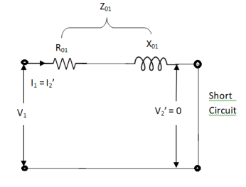
The equivalent circuit is shown below,
Z01 = Vsc/I1
Vsc = voltage to circulate rated load current
W = I21 R01
R01 = W / I21
X01 = √ Z201 – R201
R’2 = R01 – R1
Q1>. The primary and secondary windings of a 30 KVA, 5000/330 V, 1- φ transformer having resistance of 15 Ω and 0.02 Ω. The reactance referred to primary is 34 Ω. Calculate primary voltage required to circulate full-load current when the secondary is S.C. Also calculate the pf?
Sol. K = 330/5000 = 33/500
X01 = 34 Ω
R01 = R1 + R2/K2 = 15 + 0.02(500/33)2 = 19.59 Ω
Z01 = √ R201 – X201
= √ 19.592 + 342
Z01 = 39.23 Ω
F. L I1 = 30,000/5000 = 6A
Vsc = I1 Z01 = 6 x 39.23 = 235.4 V
S.C. Power factor = R01 / Z01 = 19.59/39.23 = 0.5
Q.2). In no-load test of 1- φ transformer, the test data are
Primary voltage = 200 V,
Resistance of primary = 0.6 Ω
Secondary voltage = 100 V
Primary current = 0.6 A
Power input = 30 W
Find (a) Turns ratio (b) Magnetising component of no-load current (c) Working component (d) Iron loss
Sol>. (a). N1/N2 = 200/100 = 1
(b). W = V1 I0 cos φ0
Cos φ0 = 30/200 x 0.6 = 0.25, sin φ0 = 0.97
Iµ = I0 sin φ0 = 0.6 x 0.97 = 0.58 A
©. Iw = I0 Cos φ0 = 0.6 x 0.25 = 0.15 A
(d). Cu loss = I20 R1 = (0.6)2 x 0.6 = 0.216 W
Iron loss = 30 – 0.216 = 29.78 W
Q.3 Obtain the secondary voltage when delivered 10 KW at 0.8 PF.logging . The primary volt be 220v. The 300/600 v 50H2, 1- Transformer has following test results.
O.C test-:200v, 0.8A 70W-L.V side
S.C test-: 12V,10A 80W-HV side
Soln:- O.C TEST
W= COS
COS 
70=200*0.8*Cos
Cos = 0.436
Sin =0.899
 =
= COS
COS =0.8*0.436=0.35A
I =
= sin
sin = 0.8*0.899=0.72A
 =
= =
= =571.4
 =
= =
= =277.8𝛺
S.C TEST-:
 =
= =
= =1.2A
=1.2A
K= =2
=2
Z01= =
= =0.3
=0.3
I22 =W
=W
RO2= =0.7
=0.7
R01= =
= =0.175𝛺
X01=
= 
X01 = 0.244
Output KVA = =12.5
=12.5
I2= = 20.83A
Z02=1.2A R02=0.7𝛺
X02= =0.975𝛺
Total transformer drop refereed to secondary
= I2 (RO2COS +X02Sin
 )
)
= 20.83(0.7*0.8+0.975*0.6)
= 23.85v
 = 600 - 23.85=576.15v
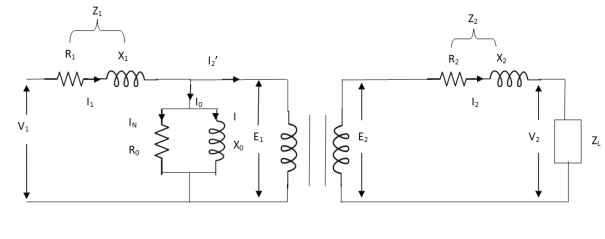
The basic transformer and its equivalent circuit both are shown below,
Fig. Equivalent Transformer Circuit
Iµ - magnetising component of current
Iw = working component
R0 – Non- inductive resistance
I0 – No load current
X0 = E1/I0. R0 = E1/Iw
E2/E1 = N2/N1 = K
E’2 = E2/K = E1
V’2 = V2/K
I’2 = K I2
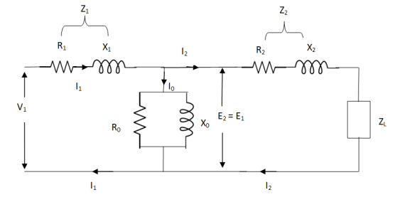
The total equivalent circuit is again given as,
But the above circuit is exact equivalent but harder to solve so, it can be further simplified as,
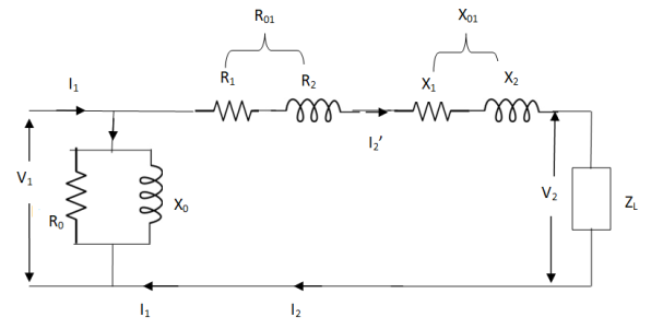
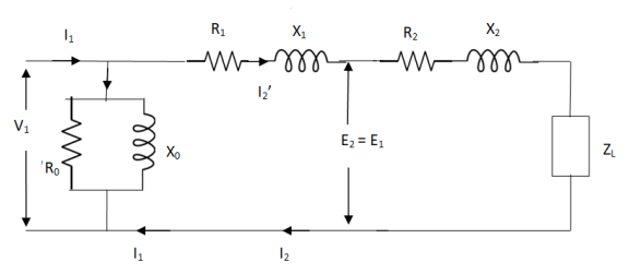
Z = Z1 + Zm || ( Z’2 + Z’L )
= Z1 + Zm(Z’2 + Z’L)/Zm + (Z’2 + Z’L)
Z’2 = R’2 + jX’2
Zm = impedance of exciting circuit
V1 = I1[ Z1 + Zm(Z’2 + Z’L) / Zm + (Z’2 + Z’L) ]
). In a 50 KVA, 2200/200 V, 1-φ transformer, the iron and full-load copper losses are 400 W and 450 W respectively. Calculate n at unity power factor on (i). Full load (ii). Half-full load?
Sol. (i). Total loss = 400 + 450 = 850 W
F.L output at unity power factor = 50 x 1
= 50 KVA
n = 50 / 50 + .850 = 50/50.850 = 0.98 = 98%
(ii). Half full load, unity pf
= 50 KVA/2 = 25 KVA
Cu loss = 400 x (1/2)2 = 100 W
Iron loss is same = 450 W
Total loss = 100 + 450 = 550 W
n = 25/25 + 0.55 = 25/25.55 = 0.978 = 97.8 %
Q>. A 40 KVA 440/220 V, 1- φ, 50 Hz transformer has iron loss of 300 W. The cu loss is found to be 100 W when delivering half full-load current. Determine (i) n when delivering full load current at 0.8 lagging pf (ii) the percentage of full-load when the efficiency will be max.
Sol. Full load efficiency at 0.8 pf
= 40 x 0.8/(40 x 0.8) + losses
Full load cu loss = (440/220)2 x 100
= 400 W
Iron loss = 400 + 300
= 700 W
n = 40 x 0.8/(40 x 0.8) + 0.7 = 97.8 %
(ii). KVA for maximum / F.L KVA = √ iron loss / F.L cu loss
= √300/400 = 0.866