Unit – 1
Introduction to Electrical Power System
Thermal Plant:
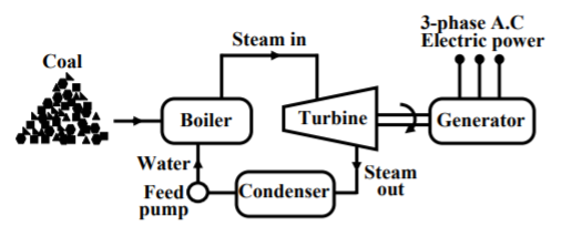
In these plants coal is burnt to produce high temperature and pressure steam in boiler. The steam produces a rotational motion when it passes through turbine. This turbine rotates and produces electricity. In India coal is present in abundance so they are commonly used. The resources used are easily available and cheap so they require less cost in installation. The main drawback of these plants is that they pollute the environment. As the coal is burnt to produce energy the leftover ash and the chimneys adds to the cost in the plant.
|
Fig 1 Thermal Plant Block diagram
We conclude the working of thermal plant by noticing that chemical energy from coal is converted to heat and steam which the turbine converts to mechanical energy to rotate and produce electricity.
Hydro power plants:
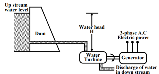
In these stations water is used to run the turbine which is coupled to the generator. The water head needed for running the generator may be available naturally in some areas or they can also be created artificially in form of dams. These plants are eco-friendly because no fuel is required to run them.
|
Fig 2 Hydro Power Plant block diagram
The above figure shows a hydro plant. The water from the dam is supplied to the water turbine, the potential energy is converted to kinetic energy making the turbine run. This kinetic energy from the turbine is converted to the electrical energy through generator. Water turbines generally operate at low rpm, so number of poles of the alternator are high.
Nuclear Power Plants:
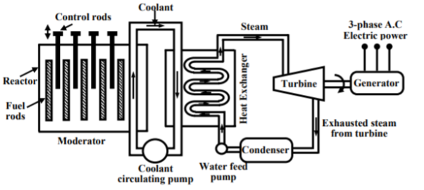
The radioactive elements like U235 and thorium are used as fuel. The nuclear reactors and heat exchanger tubes are used in place of boilers as in thermal plants.
|
Fig 3 Nuclear Power Plant block diagram
There is fission reaction takes place in the radioactive elements within the nuclear reactors. The fission reaction is a chain reaction producing huge amount of energy in the form of heat. This heat is passed to the heat exchanger tubes producing steam of very high temperature. This steam drives the turbine to produce the electricity.
Wind Energy:
Most commonly wind turbines are used. There are two types of turbines vertical axis wind turbine which has rotational vertical axis. The other is horizontal rotational axis. Wind electric generator converts kinetic energy available in wind to electrical energy by using rotor, gear box and generator. The generation of power depends upon the speed of wind. Wind turbines for remote homes (off the grid) generate DC current for battery charging. Wind turbines for remote water pumping generate 3 phase AC current suitable for driving an electrical submersible pump directly. Wind turbines suitable for residential or village scale wind power range from 500 Watts to 50 kilowatts.
Solar energy:
They are also known as renewable energy sources. The energy from renewable energy sources can be used to generate power. Solar energy most easily available and free source of energy. This energy can be used in two forms solar thermal energy and solar electric energy.
Solar Thermal Energy: Here solar energy is converted to thermal energy with help of solar devices. They are listed below
- Solar water heater: These water heaters use solar energy to heat water and then can be used for various purposes. They are used in hotels, dairies, industries etc. There is a solar collector mounted on roof top to take the sunlight. The tubes are attached to these collectors and liquid which needs to be heated is passed through it. The heat builds up in the collector, which is passed to the fluid passing through the tubes. There is an insulated tank to store this hot water.
- Solar cooker: They are used to cook food using sunlight. There are of two types box type and parabolic type. The box type cooker is painted black to absorb more heat and cook the food. The parabolic type solar cooker has a collector parabolic form which accommodates cooking vessel in at its focal point. This cooker is designed to direct the solar heat to a secondary reflector inside the kitchen, which focuses the heat to the bottom of a cooking pot. It is also possible to actually fry, bake and roast food.
Solar Electric Energy: Here PV cells are used which are made of silicon.
- Solar Photovoltaic: As soon as PV cells are exposed to light the electrons are released and current is produced. The cell is covered with metal grid to direct the flow of current. These cells connected in a panel are also used. These PV panels are installed above the roof. These panels are connected in series or parallel. The generation of power depends upon the amount of heat received from sun.
- Solar water pumps: The motor required to run the pump uses electricity generated by solar panels. It consists of a photovoltaic array mounted on a stand and a motor-pump set compatible with the photovoltaic array. It converts the solar energy into electricity, which is used for running the motor pump set. The pumping system draws water from the open well, bore well, stream, pond, canal etc
Key takeaway
Solar energy most easily available and free source of energy. This energy can be used in two forms solar thermal energy and solar electric energy.
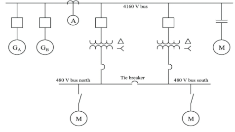
Single line diagram is the representation of a power system using the simple symbol for each component. The single line diagram of a power system is the network which shows the main connections and arrangement of the system components along with their data. In fact, the power systems are so complex that a complete conventional diagram showing all the connections is impractical. Yet, it is desirable, that there is some concise way of communicating the basic arrangement of power system components. This is done by using a Single Line Diagram (SLD). SLDs are also called One Line Diagrams.
|
Fig 4 Single Line Diagram
A generator is represented by an emf in series with an impedance. Transformers and motors are represented by their equivalent circuits. A short line is represented by its series impedance. Medium and long lines are represented by nominal PI circuits, whereas very long lines are represented by equivalent PI circuits. The shunt admittance is usually omitted in the equivalent circuit of the transformer because the magnetizing current of a transformer is usually insignificant compared with the full load current. Since the resistance of a system is very small as compared to its inductive reactance, the resistance is often omitted when making fault calculations.
The concept of bus in single line diagrams is essentially the same as the concept of a node in an electrical circuit. Just keep in mind that there is one bus for each phase. Buses are shown in SLDs as short straight lines perpendicular to transmission lines and to lines connecting equipment to the buses. In actual substations, the buses are made of aluminum or copper bars or pipes and can be several meters long. The impedance of buses is very low, practically zero, so electrically the whole bus is at the same potential.
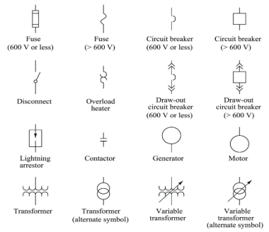
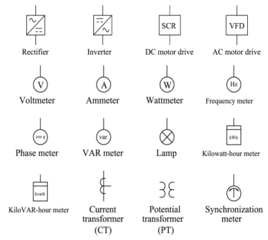
A set of commonly used single line diagram symbols are shown below.
|
Fig 5 Some Basic symbols
Key takeaway
Single line diagram is the representation of a power system using the simple symbol for each component. The single line diagram of a power system is the network which shows the main connections and arrangement of the system components along with their data.
The overhead cables or the bare conductors have been used for the transmission of electrical power and even for the distribution. These are simple in configuration and are usually commissioned using the towers or poles. The bare wire conductors on the line are generally made of aluminium. As the conductors are constantly exposed to the open atmosphere, there are several concerns related to the safety of the system and also reliability. The adverse conditions like heavy rain, wind, snowfall, humid and salty contents in the air could deteriorate the lifespan of these conductors and raise serious electrical safety concerns. Nevertheless, the most unique advantages like less cost of conductors due to less insulation levels required, ease of fault detection due to clear visibility of the conductors, relatively less cost of installation, and ease of expansion are some of the general advantages of the overhead conductors.
These advantages are backed up by several other technical advantages as well like being independent of proximity effect, relatively smaller size of conductors, relatively higher life expectancy. However, the changed perception of looking at the different premises from the point of view of aesthetic nature and the recent developments in the cable technology have made the deployment underground cables for the power distribution and even transmission more attractive in the recent times.
The underground cables provide the uninterruptable power supply which is not possible with the overhead lines due to the limitations mentioned earlier. However, there are other technical factors which also have made the underground cable to have an edge over the overhead cables which include reduced risks of fault due to external factors like rain, wind and adverse climatic conditions. The underground cables are also free from radio interference. The transmission towers are not required except for the local transformers in the system without considerable height of the tower.
However, the underground cables are not free from limitations. Damage to underground cable is difficult to locate, and restoration of the system once the faults are located might take considerably long time. For underground cable system, a large number of cables is required for the same capacity of the overhead counterpart. The construction mechanism of the underground cable involving duct bank, vaults, splices and terminations not only increase the overall cost but also might reduce the overall system reliability. This problem further might increase with the increased line length with the additional necessity of the intermediate equipment
The distribution of ac power is done in following ways
Single-phase 2 wire system
The below figure shows his type of transmission. In figure a one of the two wires is earthed and in figure b mid-point of the phase winding is earthed.
|
Fig 6 Single pahse 2 wire system (a) and (b)
Single phase 3 wire system
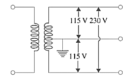
The 1-phase, 3-wire system is identical in principle with the 3-wire d.c. system. As shown below, the third wire or neutral is connected to the centre of the transformer secondary and earthed for protecting personnel from electric shock should the transformer insulation break down or the secondary main contact high voltage wire.
|
Fig 7 Single phase 3 wire system
Three phase 3 wire system
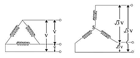
The 3-wire system can be delta or star connected with its star point earthed. This is shown below. The voltage between lines is V in delta connection and  3 V in star connection where V is voltage of each phase.
|
Fig 8 (a) Star Connected (b) Delta connected three phase 3-wire system
Three-phase, 4-wire System
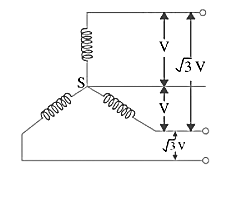
The 4th or neutral wire is taken from the star point of the star-connection as shown below and is of half the cross-section of the outers or line conductors. If V is the voltage of each winding, then line voltage is 3 V. Usually, phase voltage i.e. voltage between any outer and the neutral for a symmetrical system is 230 V so that the voltage between any two lines or outers is 3 × 230 = 400 V.
|
Fig 9 Three phase 4-wire system
Single-phase residential lighting loads or single-phase motors which run on 230 V are connected between the neutral and any one of the line wires. These loads are connected symmetrically so that line wires are loaded equally. Hence, the resultant current in the neutral wire is zero or at least minimum. The three phase induction motors requiring higher voltages of 400 V or so are put across the lines directly
Key takeaway
S.No. | Particulars | Overhead system | Underground System |
1 | Public Safety | Less Safe than Under ground | Safer |
2 | Initial Cost | Less expensive | More expensive |
3 | Faults | Frequent | Rare |
4 | Appearance | Not good | Good as wires are not visible |
5 | Flexibility | It is more flexible as new conductor can be laid along the existing conductors. | It is not flexible as new conductors are to be laid in new channels |
6 | Location of fault | Easy to locate | Difficult to locate |
7 | Repair | Easy | Difficult |
8 | Working Voltage | Up to 400kV | Up to 66kV |
It means connecting electrical equipment to earth with very low resistance wire. This ensures safe discharge of electrical energy due to failure of the insulation line coming in contact with the casing, etc. Earthing brings the potential of the body of the equipment to zero.
The main purpose of Earthing is to protect the operating personnel from shock. Under unbalanced load maintain the line voltage. To avoid risk of fire due to leakage currents. For protecting the equipment.
The earthing is broadly divided as
- System earthing (Connection between part of plant in an operating system like LV neutral of a power transformer winding) and earth.
- Equipment earthing (safety grounding) connecting bodies of equipment (like electric motor body, transformer tank, switchgear box, operating rods of air brake switches, LV breaker body, HV breaker body, feeder breaker bodies etc) to earth.
Methods of Earthing:
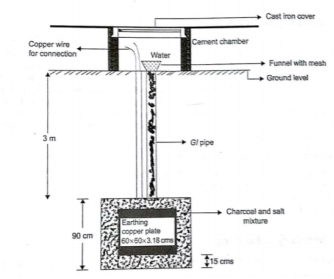
|
Fig 10 Plate Earthing
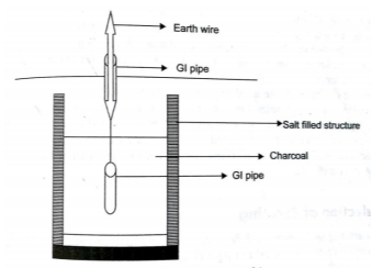
- Pipe earthing:
The earth’s electrode made of galvanized iron pipe with holes on surface is placed upright in wet ground. In order to maintain the earth’s resistance, the pipe is filled with mixture of salt and coal.
|
Fig 11 Pipe Earthing
This system can carry larger leakage currents compared to plate earthing method.
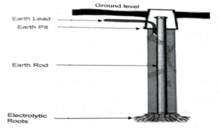
|
Fig 12 Rod Earthing
- Strip or wire earthing: In this the earthing strip electrodes are buried in horizontal trenches of depth 0.5m. The copper plate or round conductors are used. The length of the conductor buried in the ground would give a sufficient earth resistance and this length should not be less than 15m. The electrodes shall be as widely distributed as possible in a single straight or circular trench radiating from a point. This type of earthing is used where the earth bed has a rocky soil and excavation work is difficult.
Key takeaway
|
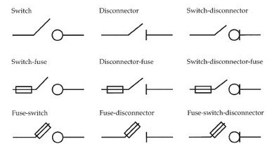
It has one switch unit and one fuse unit. When the breaker is operated the contact to the switch is close and supply passes through the fuse unit to output. In fuse switch unit there is only fuse unit which acts as a switch. During operating the fuse unit closes the input and output of the breaker.
|
HRC Fuse or High Rupturing Capacity Fuse
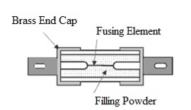
HRC fuse or high rupturing capacity fuse– In that type of fuse, the fuse wire or element can carry short circuit heavy current for a known time period. During this time if the fault gets removed, then it does not blow off. Otherwise, it blows off or melts. The enclosure of HRC fuse is either of glass or some other chemical compound.
This enclosure is sufficiently airtight to avoid the effect of the atmosphere on the fuse materials. The ceramic enclosure having a metal end cap at both heads, to which fusible silver wire gets welded. There is a space within the enclosure, surrounding the fuse wire or fuse element, completely packed with a filling powder.
Construction of HRC fuse
The construction of HRC fuse includes a material that has high heat resistant body like ceramic. This ceramic body includes metal-end caps that are welded through an element that carries silver-current.
|
Fig 14 HRC Fuse
The internal space of the fuse body is filled by a filling powder material. Here the material used in this is quartz, plaster of Paris, dust, marble, chalk, etc. So, this is the reason the flow of current cannot overheat. The generated heat vaporizes the melted element. The chemical reaction will occur between filling power and silver vapor to result in high resistance material to help in reducing the arc within the fuse.
Generally, copper or silver is used as the fuse element because of its low specific resistance. This element has normally two or more sections. The fuse element normally has two or more sections that are connected through tin joints. The melting point of tin is 2400 C that is lesser than silver’s melting point of 980o C. Thus, the melting point of tin joints stops the fuse from getting high temperatures in the short circuit and overload conditions.
Operation of HRC Fuse
When the overrated current flows through the fuse element of the high rupturing capacity fuse the element is melted and vaporized.
The filling powder is of such a quantity that the chemical reaction between the silver vapor and the filling powder forms a high electrical resistance substance which very much helps in quenching the arc. HRC fuses are used to protect the circuit from short circuits in HV switchgear. Used for backup safety Used to protect electrical devices like motors, transformers, automobiles, etc. These types of fuses are used in stators of motor.
Miniature Circuit Breaker (MCB)
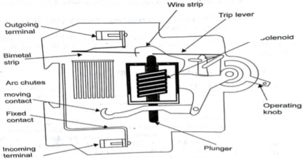
MCB is a switch which automatically turns off when the current flowing through it passes the maximum allowable limit. Generally, MCB is designed to protect against over current and over temperature faults. In MCB there are two contacts one movable and other non-movable. When the current exceeds the predefined limit, a solenoid forces the moveable contact to open and the MCB turns off, thereby stopping the current from flowing in the circuits.
It mainly consists of one bi- metallic strip, one trip coil and one hand operated on-off lever. The current in MCB flows from left side of circuit to bimetallic strip further going into the current coil, moving contact and at last through right side of circuit. When circuit is overloaded the bimetallic strip is overheated.
|
Fig 15 MCB
This deformation of bimetallic strip causes displacement in the latch. This displacement releases the spring through which the MCB is connected to the moving contact. This spring makes moving contact to open MCB.
The current coil or trip coil placed in such a manner that during SC faults, the MMF of that coil causes its plunger to hit the same latch point and force the latch to be displaced. Hence, the MCB will open in the same manner.
They are frequently used in domestic and industrial purposes. The MCB detects faults like switching, overload, short circuit protection and overload protection.
Earth Leakage Circuit Breaker (ELCB)
An Earth Leakage Circuits Breakers (ELCB) is a device used to directly detect currents leaking to earth from an installation and cut the power. There are two types of ELCBs:
- Voltage Earth Leakage Circuits Breaker (voltage -ELCB)
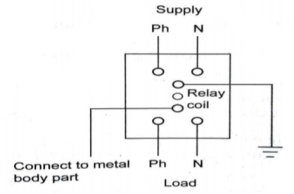
It consists of a relay coil; one end of that coil is connected to the metal body and other to the ground. When voltage on the equipment body rises to 50V (danger level) the current in the relay loop moves the relay contact by disconnecting the supply current and saves from electric shock.
|
Fig 16 Voltage-ELBC
- Current Earth Leakage Circuits Breaker (Current -ELCB)
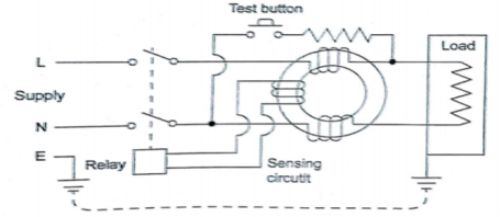
It is mostly commonly used ELCB. It consists of transformer having two primary (neutral and line wire) windings and one secondary winding. In balanced condition there is no current in secondary because the neutral wire balances the current through the phase wire.
|
Fig 17 Current-ELCB
During fault a small current flow to ground causing imbalance between line and neutral currents. As a result of which current is induced in secondary winding. The sensing circuit connected to the secondary sends signal to the tripping system and the contact is tripped.
Key takeaway
HRC fuses are used to protect the circuit from short circuits in HV switchgear. Used for backup safety Used to protect electrical devices like motors, transformers, automobiles, etc. These types of fuses are used in stators of motor
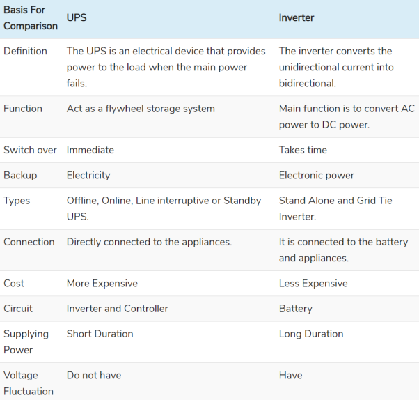
The UPS is abbreviation of uninterrupted power supply. It is used for continuous supply of power as it has a battery which supplies power when the actually supply is disconnected. Generally, the UPS system is categorised into On-line UPS, Off- line UPS and Line interactive UPS.
Off-line UPS
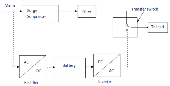
This UPS is also called as Standby UPS system which can give only the most basic features. Here, the primary source is the filtered AC mains as shown below. When the power breakage occurs, the transfer switch will select the backup source. Thus, we can clearly see that the stand by system will start working only when there is any failure in mains. In this system, the AC voltage is first rectified and stored in the storage battery connected to the rectifier.
|
Fig 18 Off-Line UPS
When power breakage occurs, this DC voltage is converted to AC voltage by means of a power inverter, and is transferred to the load connected to it. This is the least expensive UPS system and it provides surge protection in addition to back up.
On-line UPS
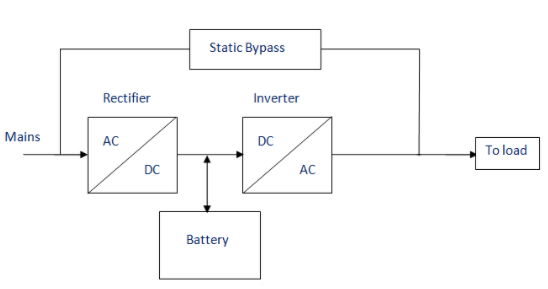
In this type of UPS, double conversion method is used. Here, first the AC input is converted into DC by rectifying process for storing it in the rechargeable battery. This DC is converted into AC by the process of inversion and given to the load or equipment which it is connected as shown below. This type of UPS is used where electrical isolation is mandatory. This system is a bit more costly due to the design of constantly running converters and cooling systems. Here, the rectifier which is powered with the normal AC current is directly driving the inverter. Hence it is also known as Double conversion UPS.
|
Fig 19 On-Line UPS
When there is any power failure, the rectifier has no role in the circuit and the steady power stored in the batteries which is connected to the inverter is given to the load by means of transfer switch. Once the power is restored, the rectifier begins to charge the batteries. To prevent the batteries from overheating due to the high-power rectifier, the charging current is limited.
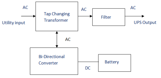
It almost same as the off-line UPS and is used for small business and departmental server. Here additional tap changing transformer is used. This transformer is controlling the voltage regulation by changing the tap depending on the input voltage.
|
Fig 20 Line Interactive UPS
The inverter inverts the direct current to an alternating current. It takes the supply from the AC source and charges the battery. During the power cut, the inverter receives the supply from the battery and provides the power supply to the electrical equipment.
Key takeaway
|
Reference:
1) Basic Electrical Engineering, S.N. Singh, PHI, Learning Private Limited.
2) A Text Book Of Electrical Technology, B. L. Tharaja and A. K. Tharaja, S. Chand
Publication (Volume II & III)
3) Electrical Machines M. N. Bandyopadhya, PHI, Learning Private Limited.
4) Electrical Machines, Ashfaq Husain, Dhanpatrai Company, 4th edition.
5) Basic Electrical Engineering, D.C. Kulshreshtha, revised 1st edition, Tata Mc-Graw Hill education pvt. Ltd.
6) Generation of Electrical Energy- B. R. Gupta 4th Edition S Chand Publication
7) Testing Commissioning Operation & Maintenance Of Electrical Equipment – S. Rao Khanna Publication
