Unit - 2
Equations of Equilibrium
To apply the equation of equilibrium, we have to consider all types of forces (ΣF) which are acting on the particle. A drawing in which all the forces are depicted is called free body diagram (FBD).
Process to Draw a Free-Body Diagram
To construct a free body diagram, the following three steps are necessary.
a. Draw Outlined Shape.
Imagine that the particle is to be isolated from its environments by drawing its outlined shape.
b. Show All the forces.
Then on this sketch, show all the types of forces. Identify Each Force that are known and unknown and display them.
c. Identify each force
Known forces are displayed with magnitude and direction. Letters are used to represent the magnitudes and directions of forces that are unknown.
For understanding the free-body diagram, we will consider the following example:
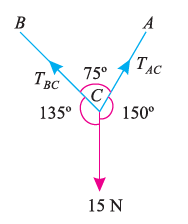
Suppose, in this example there are two strings (AC and BC) attached to an object at point C. Thus, the first step involves drawing a simple diagram representing the outline of all components.
Then, we need to show all the forces that are contributing in the given diagram. Here, there is 15 N force acting at point C, and there is tension in strings BC and AC due to 15 N force acting at C. Thus, identifying and displaying these forces onto the outline diagram is the second step.
The third step is finding the magnitude and direction of the forces and displaying them on the outline diagram. Using these steps, we can draw the free-body diagram as shown below.
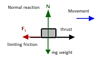
- A body is said to be in equilibrium if the resultant of all forces acting on it is zero.
- When the resultant of all the forces acting on the particle is zero, then, the particle is in equilibrium.
- If the resultant force acting on a particle is zero (or if particle is in equilibrium state) the, particle will remain at rest condition if it is originally at rest; or particle will move with constant speed in a straight line if it is originally in motion.
Condition for Equilibrium: R = 0 {  }
}
∑M = 0
Coplanar concurrent forces:
The forces which meet at one point & their lines of action also lie on the same plane are called as coplanar concurrent force system.
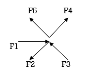
Coplanar non concurrent forces:
The forces which do not meet at one point but their line of action lies on the same plane are known as coplanar non-concurrent system of force.
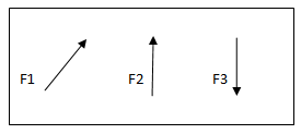
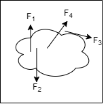
When a single agency is acting on body then it is known as force. But when no of forces are acting on the body simultaneously, then it is known “System of force”.
Types of Force System:
1. Co-planer Forces
2. Non Co-planer Forces
3. Co-linear Forces
4. Non Co-linear Forces
5. Concurrent Forces
6. Non Concurrent Forces
7. Parallel Forces (Like & unlike)
8. Coplanar Concurrent Forces
9>. Coplanar Non Concurrent Forces
10. Non Coplanar Concurrent Forces
11. Non Coplanar Non Concurrent Forces
The analysis of pin joined is explained below
Truss:
A Rigid structure formed by connecting various two force members to each other by using pin joint.
Plane truss:
When all members of the truss lies in one plane, then truss is known as plane truss
Rigid truss:
A truss which does not collapse when external Load is applied on it.
Simple truss:
The structure formed by basic triangle made by connecting various members are called simple truss
Classification of Truss:
1. Perfect truss (Stable) (n=2j- R)
2. Imperfect (unstable) (n  2j- R):
- Deficient Truss (n< 2 j – R)
- Redundant Truss (Over stable) (n> 2 j – R)
Perfect truss:
A truss which does not collapse under the action of Load is called perfect truss. Condition: n = 2 j-R
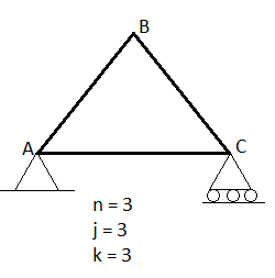
n= no. Of member
j = no of joints
R = no. Of reaction
In truss ABC, n = 3 & 2 j- R+3
So it is perfect truss
Imperfect truss:
A truss which does not collapse under the load is called Imperfect or unstable truss.
Here n 2j -R
2j -R
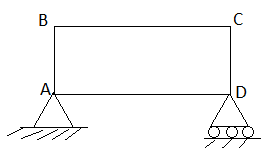
- Over stable (Redundant Truss)
A truss in which n > 2j- R,
Then it is over stable truss.
Diagram
- Deficient truss
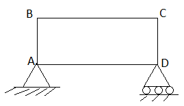
It is a truss in which
N <2 j-R.
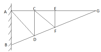
Cantilever Truss:
A truss which is fixed on one side & free of other end is called as cantilever truss.
Assumption made in the analysis:
1) Given truss a perfect truss
2) The truss member is connected by joints only.
3) External loads are acting at the joints only.
4) All members are two force members.
5) The self- weight of members is neglected.
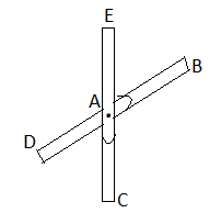
1) If when four members are connected At Engile joint in such a way That opposite members lie in a Single straight line
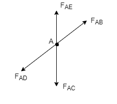
There is No external load acting at the joint Then Forces in the opposite members Are equal.
FAE = FAC & FAB = FAD.
2) If there are only there members at a joint and Out of there, two are collinear and is inclined to first two or lar to first members, With no external load at joint,
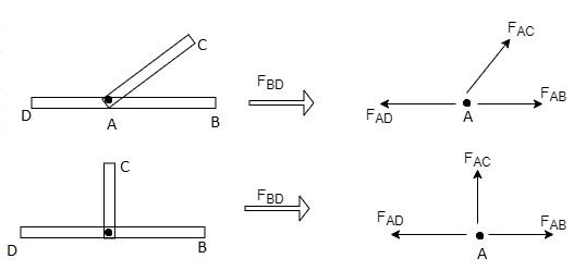
Then,
a) Forces in the two opposite ( co- linear) members
Are equal. l.e FAD = FAB
b) The force in the inclined member is zero
i.e FAC =0
c) Force in the perpendicular member is zero
FAC = 0
3) If there are two member at a joint with one Member Horizontal & one vertical, & there is no external load of joint.
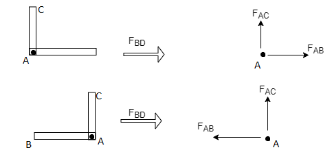
Then, both members are zero force members,
Angle FAB=0
FAC =0
4) If there are only two members at joint With- one member vertical & other inclined & there is no external load of joint,

Then both members are zero force members
i.e. FAB = 0 & FAC =0
One member Horizontal & other inclined and there is No external load at joint.
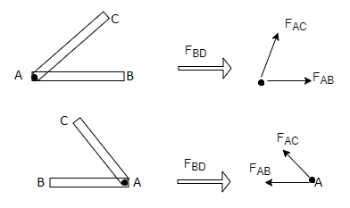
Then both members are zero force members
FAB = 0 and FAC =0
5) if there are only two members at a joint with one member Horizontal & other inclined and there is no External load at joint
Diagram

Then both members are zero force member
FAB=0 and FAC = 0
Numerical:
Analysis of Truss By method of joint method
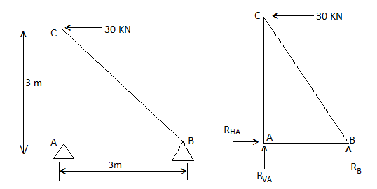
1) Determine the forces in all members of truss by joint method
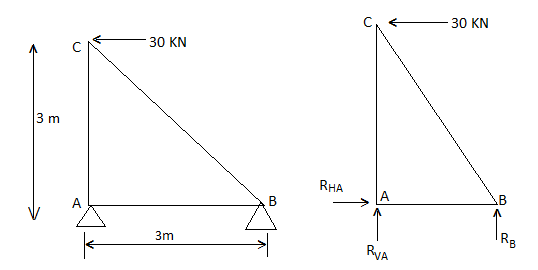
Consider FAB of Truss, Applying conditions of equilibrium,
 = 0
= 0
RHA + 30 Kn
 = 0
= 0
RvA + RB =0
Taking moment at point A, = 0
= 0
-(RB* 3) - (30*3) = 0
RB = -30 KN
RB =30 KN RVA = 30 KN
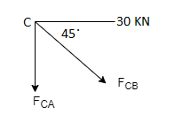
Consider Joint c, assuming forces in member AC & BC to be
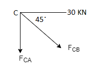
Tensile, applying conditions of equilibrium,
 = 0
= 0
-30 + FCB cos 45 =0
FCB =30/cos 45 = 42.42 KN (T)
-  = 0
= 0
- FcA – FCB sin 45= 0
-F CA -42.42 sin 45 =0
-FCA – 30= 0
-FCA = -30 KN
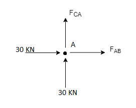
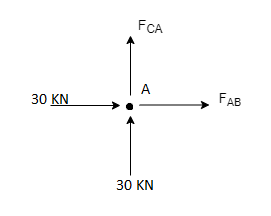
Consider Joint c, assuming forces in member AC & BC to be
Tensile, applying conditions of equilibrium,
 Fx = 0 30+FAB =0
FAB = -30KN
When the two objects slide over each other the force which opposes this type of motion is called as Friction. This force always acts tangentially to the surface and its direction is opposite to that of the motion of bodies.
Laws of Coulomb’s Friction
Coulomb friction is also known as Dry friction and was named after C. A. Coulomb who extensively studied this phenomenon. Dry friction is considered to exist between the two surfaces of objects which are in contact when there is absence of any kind of fluid lubrication.
Dry friction may take place either due to adhesion between the surfaces, or roughness or contamination of surfaces taking place.
As there is loss of mechanical energy in the form of heat during the frictional process, it turns out to be non-conservative force that is path dependent.
The force of friction is always applied in a manner that opposes the movement created within the two surfaces. Any object moving on a road or any surface slows down and then eventually stops.
Dry friction is can be further classified into static friction which is between non-moving surfaces, and kinetic friction which is between moving surfaces.
The laws are discussed as:
Laws of Static Friction:
Following are the laws of static friction
1. The force of friction always act in direction which is opposite to motion of body.
2. The magnitude of force of friction is equal to the force acting on the body externally.
3. There is constant ratio between limiting frictional force and the normal reaction forces. Mathematically:
(F/R) = Constant
Where F = Limiting friction, and R = Normal reaction.
4. The force of friction does not depend on the area of contact between the two surfaces.
5. There is dependency of frictional force on roughness of the surfaces.
Laws of Kinematic or Dynamic Friction:
Following are the laws of kinetic or dynamic friction:
1. The force of friction always act such that it opposes the motion of body.
2. There is a constant ratio between kinetic motion and normal reaction. But this ratio is slightly less when it comes to limiting friction.
3. For medium speeds, the force due to friction stays constant. But it decreases somewhat when the speed increases.
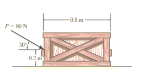
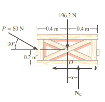
e.g. 1: The uniform crate shown in Fig. Below has a mass of 20 kg. If a force P = 80 N is applied to the crate, determine if it remains in equilibrium. The coefficient of static friction is s = 0.3.
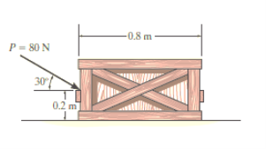
Solution:
The first step is free-body diagram i.e.
Free-Body Diagram. As shown in Fig. Diagram below, the resultant normal force NC acts at a distance of x from the centre line of crate for countering the tilting effect caused by P. Hence, there are three unknowns, F, NC and x, which can be solved by equations of equilibrium.
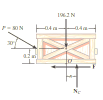
Equations of equilibrium:
ΣFx= 0
80 cos 30° N - F = 0
ΣFy= 0
-80 sin 30° N + NC - 196.2 N = 0
Σ M= 0
80 sin 30° N10.4 m2 - 80 cos 30° N10.2 m2 + NC (x) = 0
Thus, solving the above equations, we get,
F = 69.3 N
NC = 236 N
x = -0.00908 m = -9.08 mm
As value of x is negative, hence it acts to left of centre line of the crate. There will be no tipping since x < 0.4 m. Fmax = 𝛍Nc = 0.3(236 N) = 70.8 N. Since F that we got is 69.3 N < 70.8 N, the crate will not slip.
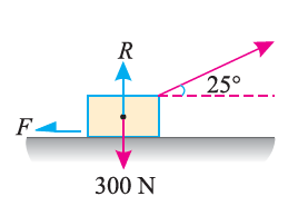
e.g. 2: A body of weight 300 N is lying on a rough horizontal plane having a coefficient of friction as 0.3. Determine the magnitude of the force, which is needed to move the body, acting at 25° by the horizontal.
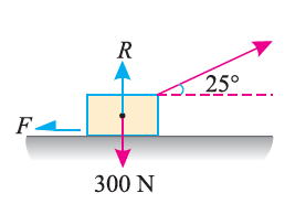
Solution:
Given:
Weight of the body (W) = 300 N; Coefficient of friction (μ) = 0.3 and
Angle made by the force with the horizontal (α) = 25°
Let P = Magnitude of the force, which can move the body, and
F = Force of friction.
Initially, we will solve the problem in horizontal direction as,
F = P * cos α = P * cos 25o = P * 0.9063
The next step is to resolve the force in vertical direction, we get,
R = W – P * sin α
= 300 – P * sin 25o
= (300 – P * 0.4226)
The force of friction (F) is given as,
0.9063 P = μ * R = 0.3 * (300 – 0.4226 * P) = 90 – 0.12268 P
Or 90 = 0.9063 * P + 0.1268 * P = 1.0331 P
Hence, P = 87.1 N.
e.g. 3: A body, which is positioned on a rough horizontal plane, needs a pull of 180 N inclined at 30° to the plane just for moving. Also, it was found that a push of 220 N which is inclined at 30° to the plane also moved the body. Find out the weight of the body and the coefficient of friction present here.

Solution:
Given: Pull = 180 N; Push = 220 N and angle at which force is inclined with horizontal plane (α) = 30°
Let W = Weight of the body
R = Normal reaction, and
μ = Coefficient of friction.
First of all, consider a pull of 180 N acting on the body. We know that in this case, the force of friction (F1) will act towards left as shown in Fig. (a).
Resolving the forces horizontally,
F1 = 180 cos 30° = 180 × 0.866 = 155.9 N
And now resolving the forces vertically,
R1 = W – 180 sin 30° = W – 180 × 0.5 = W – 90 N
We know that the force of friction (F1),
155.9 = μR1 = μ (W – 90)
Now consider a push of 220 N acting on the body. We know that in this case, the force of friction (F2) will act towards right as shown in Fig. (b).
Resolving the forces horizontally,
F2 = 220 cos 30° = 220 × 0.866 = 190.5 N
And now resolving the forces horizontally,
R2 = W + 220 sin 30° = W + 220 × 0.5 = W + 110 N
We know that the force of friction (F2),
190.5 = μ.R2 = μ (W + 110) ...(ii)
Dividing equation (i) by (ii)
155.9 W + 17 149 = 190.5 W – 17 145
34.6 W = 34 294
W = 991.2 N
Now substituting the value of W in equation (i),
155.9 = μ (991.2 – 90) = 901.2 μ
μ = 0.173
In this way, numerical based on dry friction can be solved.
Friction is defined as a force of resistance acting on a body which prevents or retards slipping of the body relative to a second body. Experiments show that frictional forces act tangent (parallel) to the contacting surface in a direction opposing the relative motion or tendency for motion.
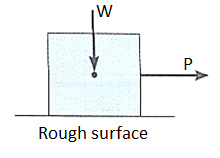
For the body shown in the figure to be in equilibrium, the following must be true:
F = P, N = W, and Wx = Ph
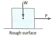
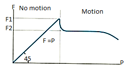
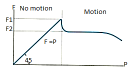
To study the characteristics of the friction force F, let us assume that tipping does not occur (i.e., “h” is small or “a” is large). Then we gradually increase the magnitude of the force P. Typically, experiments show that the friction force F varies with P, as shown in the right figure above.
The maximum friction force is attained just before the block begins to move (a situation that is called “impending motion”). The value of the force is found using Fs =s N, where s is called the coefficient of static friction. The value of s depends on the materials in contact. Once the block begins to move, the frictional force typically drops and is given by Fk = k N. The value of k (coefficient of kinetic friction) is less than s.
Steps for solving equilibrium problems involving dry friction:
1. Draw the necessary free body diagrams. Make sure that you show the friction force in the correct direction (it always opposes the motion or impending motion).
2. Determine the number of unknowns. Do not assume F =sN unless the impending motion condition is given.
3. Apply the equations of equilibrium and appropriate frictional equations to solve for the unknowns.
Simple application like wedges:
Wedges are a useful engineering tool, and the approach used for wedges also finds its way into other engineering applications.
A good rule to stick to is that when a wedge is in use, the forces on the faces will both be in the same direction. That is either towards, or away from the point of the wedge.

When solving friction problems we look for friction that is about to let go and start slipping. Keep in mind that not all surfaces will slip, this should be verified after the solution. For all surfaces that slip the friction force will be at the maximum value.
The example below shows how to deal with a multiple wedge problem.
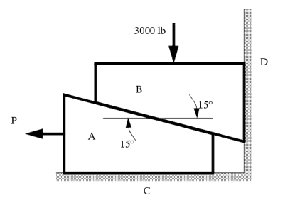
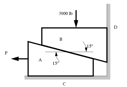
The two wedges are stacked as shown, and a load is applied. What is the minimum force P required to pull the bottom wedge out?
μAB = 0.1
μAC = 0.2
μBD = 0.2
Sol:
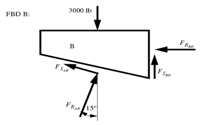
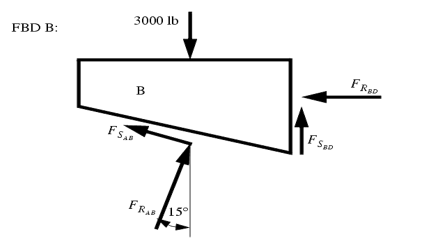
These types of problems involve a large number of forces, and should not be attempted without FBDs. So, the first step is to draw FBDs of one of the wedges. The first wedge to be considered is B. When the bottom wedge slips out, B will push against the wall, and slide down, but A will try to pull it away from the wall.
+ 
- μAB  cos 15o +
  sin 15o =
+  - 3000 lb +
  +
+  sin (15o) +
  cos 15o = 0
μBD (-μAB  cos 15o +
  sin 15o ) +
  sin(15o) +
  cos 15o = 3000lb
 =
=  = 2929 lb

Band – Brake:
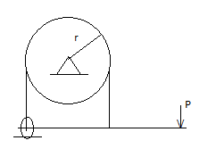
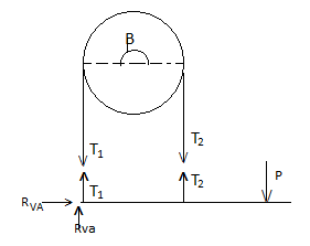
Simple Band Brake:
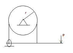
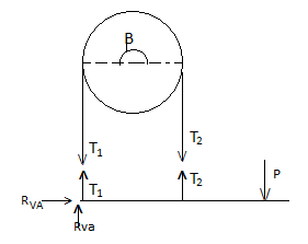
Friction can be used as a power-transmitting agent (in belts-pulleys) as well as a power-absorbing agent (in band brakes). The idea is, the band resists the motion of rotating wheel through friction. The braking torque is obtained by the relations
T1/T2 = eμβ
And
Torque = (T1 – T2) radius of wheel
In this case, the values of T1 and T2 depend on the applied force P as well. Drawing the free body diagram of lever and pulley is necessary.
References:
1. Engineering Mechanics: F. L. Singer
2. Engineering Mechanics: Timoshenko & Young
3. Engineering Mechanics: Bear & Johnston
4. Engineering Mechanics: I. H. Shames
5. Engineering Mechanics: A. Nelson
Unit - 2
Equations of Equilibrium
To apply the equation of equilibrium, we have to consider all types of forces (ΣF) which are acting on the particle. A drawing in which all the forces are depicted is called free body diagram (FBD).
Process to Draw a Free-Body Diagram
To construct a free body diagram, the following three steps are necessary.
a. Draw Outlined Shape.
Imagine that the particle is to be isolated from its environments by drawing its outlined shape.
b. Show All the forces.
Then on this sketch, show all the types of forces. Identify Each Force that are known and unknown and display them.
c. Identify each force
Known forces are displayed with magnitude and direction. Letters are used to represent the magnitudes and directions of forces that are unknown.
For understanding the free-body diagram, we will consider the following example:
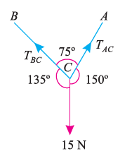
Suppose, in this example there are two strings (AC and BC) attached to an object at point C. Thus, the first step involves drawing a simple diagram representing the outline of all components.
Then, we need to show all the forces that are contributing in the given diagram. Here, there is 15 N force acting at point C, and there is tension in strings BC and AC due to 15 N force acting at C. Thus, identifying and displaying these forces onto the outline diagram is the second step.
The third step is finding the magnitude and direction of the forces and displaying them on the outline diagram. Using these steps, we can draw the free-body diagram as shown below.
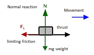
- A body is said to be in equilibrium if the resultant of all forces acting on it is zero.
- When the resultant of all the forces acting on the particle is zero, then, the particle is in equilibrium.
- If the resultant force acting on a particle is zero (or if particle is in equilibrium state) the, particle will remain at rest condition if it is originally at rest; or particle will move with constant speed in a straight line if it is originally in motion.
Condition for Equilibrium: R = 0 {  }
}
∑M = 0
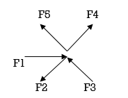
Coplanar concurrent forces:
The forces which meet at one point & their lines of action also lie on the same plane are called as coplanar concurrent force system.
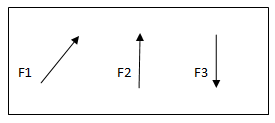
Coplanar non concurrent forces:
The forces which do not meet at one point but their line of action lies on the same plane are known as coplanar non-concurrent system of force.
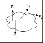
When a single agency is acting on body then it is known as force. But when no of forces are acting on the body simultaneously, then it is known “System of force”.
Types of Force System:
1. Co-planer Forces
2. Non Co-planer Forces
3. Co-linear Forces
4. Non Co-linear Forces
5. Concurrent Forces
6. Non Concurrent Forces
7. Parallel Forces (Like & unlike)
8. Coplanar Concurrent Forces
9>. Coplanar Non Concurrent Forces
10. Non Coplanar Concurrent Forces
11. Non Coplanar Non Concurrent Forces
The analysis of pin joined is explained below
Truss:
A Rigid structure formed by connecting various two force members to each other by using pin joint.
Plane truss:
When all members of the truss lies in one plane, then truss is known as plane truss
Rigid truss:
A truss which does not collapse when external Load is applied on it.
Simple truss:
The structure formed by basic triangle made by connecting various members are called simple truss
Classification of Truss:
1. Perfect truss (Stable) (n=2j- R)
2. Imperfect (unstable) (n  2j- R):
- Deficient Truss (n< 2 j – R)
- Redundant Truss (Over stable) (n> 2 j – R)
Perfect truss:
A truss which does not collapse under the action of Load is called perfect truss. Condition: n = 2 j-R
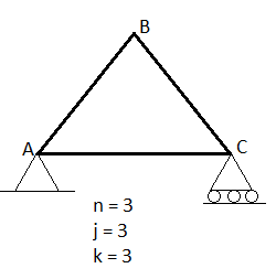
n= no. Of member
j = no of joints
R = no. Of reaction
In truss ABC, n = 3 & 2 j- R+3
So it is perfect truss
Imperfect truss:
A truss which does not collapse under the load is called Imperfect or unstable truss.
Here n 2j -R
2j -R
- Over stable (Redundant Truss)
A truss in which n > 2j- R,
Then it is over stable truss.
Diagram
- Deficient truss
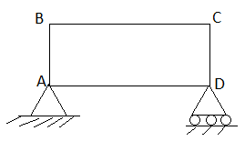
It is a truss in which
N <2 j-R.
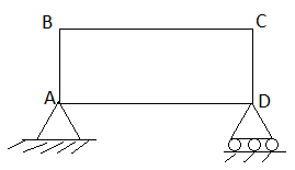
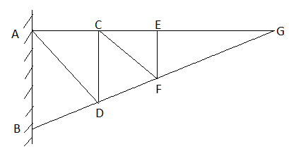
Cantilever Truss:
A truss which is fixed on one side & free of other end is called as cantilever truss.
Assumption made in the analysis:
1) Given truss a perfect truss
2) The truss member is connected by joints only.
3) External loads are acting at the joints only.
4) All members are two force members.
5) The self- weight of members is neglected.
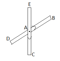
1) If when four members are connected At Engile joint in such a way That opposite members lie in a Single straight line
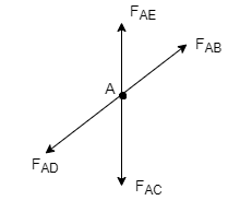
There is No external load acting at the joint Then Forces in the opposite members Are equal.
FAE = FAC & FAB = FAD.
2) If there are only there members at a joint and Out of there, two are collinear and is inclined to first two or lar to first members, With no external load at joint,
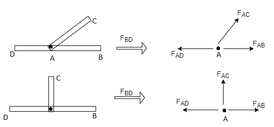
Then,
a) Forces in the two opposite ( co- linear) members
Are equal. l.e FAD = FAB
b) The force in the inclined member is zero
i.e FAC =0
c) Force in the perpendicular member is zero
FAC = 0
3) If there are two member at a joint with one Member Horizontal & one vertical, & there is no external load of joint.
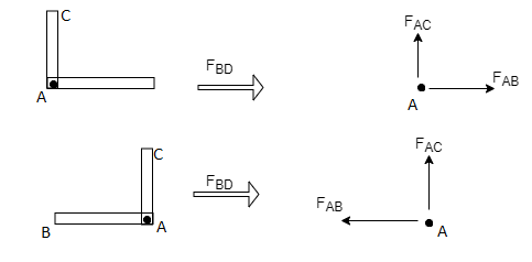
Then, both members are zero force members,
Angle FAB=0
FAC =0
4) If there are only two members at joint With- one member vertical & other inclined & there is no external load of joint,

Then both members are zero force members
i.e. FAB = 0 & FAC =0
One member Horizontal & other inclined and there is No external load at joint.
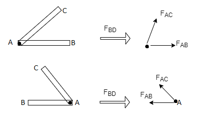
Then both members are zero force members
FAB = 0 and FAC =0
5) if there are only two members at a joint with one member Horizontal & other inclined and there is no External load at joint
Diagram

Then both members are zero force member
FAB=0 and FAC = 0
Numerical:
Analysis of Truss By method of joint method
1) Determine the forces in all members of truss by joint method
Consider FAB of Truss, Applying conditions of equilibrium,
 = 0
= 0
RHA + 30 Kn
 = 0
= 0
RvA + RB =0
Taking moment at point A, = 0
= 0
-(RB* 3) - (30*3) = 0
RB = -30 KN
RB =30 KN RVA = 30 KN
Consider Joint c, assuming forces in member AC & BC to be
Tensile, applying conditions of equilibrium,
 = 0
= 0
-30 + FCB cos 45 =0
FCB =30/cos 45 = 42.42 KN (T)
-  = 0
= 0
- FcA – FCB sin 45= 0
-F CA -42.42 sin 45 =0
-FCA – 30= 0
-FCA = -30 KN
Consider Joint c, assuming forces in member AC & BC to be
Tensile, applying conditions of equilibrium,
 Fx = 0 30+FAB =0
FAB = -30KN
When the two objects slide over each other the force which opposes this type of motion is called as Friction. This force always acts tangentially to the surface and its direction is opposite to that of the motion of bodies.
Laws of Coulomb’s Friction
Coulomb friction is also known as Dry friction and was named after C. A. Coulomb who extensively studied this phenomenon. Dry friction is considered to exist between the two surfaces of objects which are in contact when there is absence of any kind of fluid lubrication.
Dry friction may take place either due to adhesion between the surfaces, or roughness or contamination of surfaces taking place.
As there is loss of mechanical energy in the form of heat during the frictional process, it turns out to be non-conservative force that is path dependent.
The force of friction is always applied in a manner that opposes the movement created within the two surfaces. Any object moving on a road or any surface slows down and then eventually stops.
Dry friction is can be further classified into static friction which is between non-moving surfaces, and kinetic friction which is between moving surfaces.
The laws are discussed as:
Laws of Static Friction:
Following are the laws of static friction
1. The force of friction always act in direction which is opposite to motion of body.
2. The magnitude of force of friction is equal to the force acting on the body externally.
3. There is constant ratio between limiting frictional force and the normal reaction forces. Mathematically:
(F/R) = Constant
Where F = Limiting friction, and R = Normal reaction.
4. The force of friction does not depend on the area of contact between the two surfaces.
5. There is dependency of frictional force on roughness of the surfaces.
Laws of Kinematic or Dynamic Friction:
Following are the laws of kinetic or dynamic friction:
1. The force of friction always act such that it opposes the motion of body.
2. There is a constant ratio between kinetic motion and normal reaction. But this ratio is slightly less when it comes to limiting friction.
3. For medium speeds, the force due to friction stays constant. But it decreases somewhat when the speed increases.
e.g. 1: The uniform crate shown in Fig. Below has a mass of 20 kg. If a force P = 80 N is applied to the crate, determine if it remains in equilibrium. The coefficient of static friction is s = 0.3.
Solution:
The first step is free-body diagram i.e.
Free-Body Diagram. As shown in Fig. Diagram below, the resultant normal force NC acts at a distance of x from the centre line of crate for countering the tilting effect caused by P. Hence, there are three unknowns, F, NC and x, which can be solved by equations of equilibrium.
Equations of equilibrium:
ΣFx= 0
80 cos 30° N - F = 0
ΣFy= 0
-80 sin 30° N + NC - 196.2 N = 0
Σ M= 0
80 sin 30° N10.4 m2 - 80 cos 30° N10.2 m2 + NC (x) = 0
Thus, solving the above equations, we get,
F = 69.3 N
NC = 236 N
x = -0.00908 m = -9.08 mm
As value of x is negative, hence it acts to left of centre line of the crate. There will be no tipping since x < 0.4 m. Fmax = 𝛍Nc = 0.3(236 N) = 70.8 N. Since F that we got is 69.3 N < 70.8 N, the crate will not slip.
e.g. 2: A body of weight 300 N is lying on a rough horizontal plane having a coefficient of friction as 0.3. Determine the magnitude of the force, which is needed to move the body, acting at 25° by the horizontal.
Solution:
Given:
Weight of the body (W) = 300 N; Coefficient of friction (μ) = 0.3 and
Angle made by the force with the horizontal (α) = 25°
Let P = Magnitude of the force, which can move the body, and
F = Force of friction.
Initially, we will solve the problem in horizontal direction as,
F = P * cos α = P * cos 25o = P * 0.9063
The next step is to resolve the force in vertical direction, we get,
R = W – P * sin α
= 300 – P * sin 25o
= (300 – P * 0.4226)
The force of friction (F) is given as,
0.9063 P = μ * R = 0.3 * (300 – 0.4226 * P) = 90 – 0.12268 P
Or 90 = 0.9063 * P + 0.1268 * P = 1.0331 P
Hence, P = 87.1 N.
e.g. 3: A body, which is positioned on a rough horizontal plane, needs a pull of 180 N inclined at 30° to the plane just for moving. Also, it was found that a push of 220 N which is inclined at 30° to the plane also moved the body. Find out the weight of the body and the coefficient of friction present here.

Solution:
Given: Pull = 180 N; Push = 220 N and angle at which force is inclined with horizontal plane (α) = 30°
Let W = Weight of the body
R = Normal reaction, and
μ = Coefficient of friction.
First of all, consider a pull of 180 N acting on the body. We know that in this case, the force of friction (F1) will act towards left as shown in Fig. (a).
Resolving the forces horizontally,
F1 = 180 cos 30° = 180 × 0.866 = 155.9 N
And now resolving the forces vertically,
R1 = W – 180 sin 30° = W – 180 × 0.5 = W – 90 N
We know that the force of friction (F1),
155.9 = μR1 = μ (W – 90)
Now consider a push of 220 N acting on the body. We know that in this case, the force of friction (F2) will act towards right as shown in Fig. (b).
Resolving the forces horizontally,
F2 = 220 cos 30° = 220 × 0.866 = 190.5 N
And now resolving the forces horizontally,
R2 = W + 220 sin 30° = W + 220 × 0.5 = W + 110 N
We know that the force of friction (F2),
190.5 = μ.R2 = μ (W + 110) ...(ii)
Dividing equation (i) by (ii)
155.9 W + 17 149 = 190.5 W – 17 145
34.6 W = 34 294
W = 991.2 N
Now substituting the value of W in equation (i),
155.9 = μ (991.2 – 90) = 901.2 μ
μ = 0.173
In this way, numerical based on dry friction can be solved.
Friction is defined as a force of resistance acting on a body which prevents or retards slipping of the body relative to a second body. Experiments show that frictional forces act tangent (parallel) to the contacting surface in a direction opposing the relative motion or tendency for motion.
For the body shown in the figure to be in equilibrium, the following must be true:
F = P, N = W, and Wx = Ph
To study the characteristics of the friction force F, let us assume that tipping does not occur (i.e., “h” is small or “a” is large). Then we gradually increase the magnitude of the force P. Typically, experiments show that the friction force F varies with P, as shown in the right figure above.
The maximum friction force is attained just before the block begins to move (a situation that is called “impending motion”). The value of the force is found using Fs =s N, where s is called the coefficient of static friction. The value of s depends on the materials in contact. Once the block begins to move, the frictional force typically drops and is given by Fk = k N. The value of k (coefficient of kinetic friction) is less than s.
Steps for solving equilibrium problems involving dry friction:
1. Draw the necessary free body diagrams. Make sure that you show the friction force in the correct direction (it always opposes the motion or impending motion).
2. Determine the number of unknowns. Do not assume F =sN unless the impending motion condition is given.
3. Apply the equations of equilibrium and appropriate frictional equations to solve for the unknowns.
Simple application like wedges:
Wedges are a useful engineering tool, and the approach used for wedges also finds its way into other engineering applications.
A good rule to stick to is that when a wedge is in use, the forces on the faces will both be in the same direction. That is either towards, or away from the point of the wedge.

When solving friction problems we look for friction that is about to let go and start slipping. Keep in mind that not all surfaces will slip, this should be verified after the solution. For all surfaces that slip the friction force will be at the maximum value.
The example below shows how to deal with a multiple wedge problem.
The two wedges are stacked as shown, and a load is applied. What is the minimum force P required to pull the bottom wedge out?
μAB = 0.1
μAC = 0.2
μBD = 0.2
Sol:
These types of problems involve a large number of forces, and should not be attempted without FBDs. So, the first step is to draw FBDs of one of the wedges. The first wedge to be considered is B. When the bottom wedge slips out, B will push against the wall, and slide down, but A will try to pull it away from the wall.
+ 
- μAB  cos 15o +
  sin 15o =
+  - 3000 lb +
  +
+  sin (15o) +
  cos 15o = 0
μBD (-μAB  cos 15o +
  sin 15o ) +
  sin(15o) +
  cos 15o = 3000lb
 =
=  = 2929 lb

Band – Brake:
Simple Band Brake:
Friction can be used as a power-transmitting agent (in belts-pulleys) as well as a power-absorbing agent (in band brakes). The idea is, the band resists the motion of rotating wheel through friction. The braking torque is obtained by the relations
T1/T2 = eμβ
And
Torque = (T1 – T2) radius of wheel
In this case, the values of T1 and T2 depend on the applied force P as well. Drawing the free body diagram of lever and pulley is necessary.
References:
1. Engineering Mechanics: F. L. Singer
2. Engineering Mechanics: Timoshenko & Young
3. Engineering Mechanics: Bear & Johnston
4. Engineering Mechanics: I. H. Shames
5. Engineering Mechanics: A. Nelson