Unit - 1
Introduction of Statically indeterminate Structures
Static Indeterminacy:
The Static Indeterminacy (SI) for beams and frames is described as,
SI = nu — ne
Where,
nu = Number of unknown assist reactions
ne = Number of equations of equilibrium
In fashionable for a -dimensional shape, there are 3 equations of equilibrium (ne = 3) and for a 3-dimensional shape there are six (ne = 6).
For a truss, static indeterminacy entails each outside and inner indeterminacy due to the inner individuals in a truss.
Static indeterminacy (SI) within side the case of a truss is described as,
SI = b + r — 2j
Where,
b = Number of individuals within side the truss
r = Number of reactions on the supports
j = Number of joints within side the truss
Sign Conventions
1). Static Calculations
∑F x = 0, ∑F y = 0 & ∑M = 0
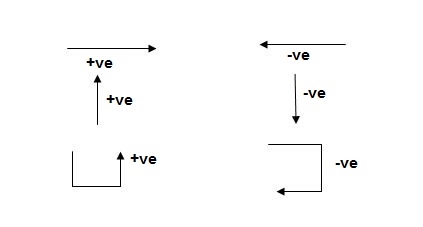
For Structural Actions
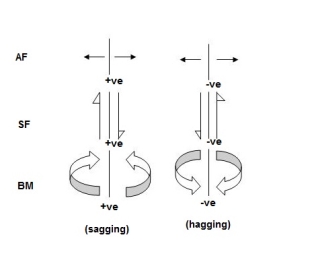
Degree of static indeterminacy (Dsi)
Dsi = No of Unknown Actions –No of Eqn,
Dsi = R – E
External Indeterminacy
When we can't discover assist reactions the use of legal guidelines at statics, its miles referred to as externally indeterminate structure.
Internal Indeterminacy
When we can't discover inner member movements the use of legal guidelines of statics, its miles referred to as internally indeterminate structure.
Boundary condition
Displacement Re stained Displacement allow
Δx, Δy, ϴz Nil
Δy,ϴz, Δx
Δx, Δyϴz
Dsi for beams = R – E
Where,
R = No of assist reactions
E = No of Equilibrium equations
Note: For one inner pin, no of extra equations of equilibrium are = m – 1
m = no of individuals linked via way of means of pin.
Sr. No Structure R E Dsi
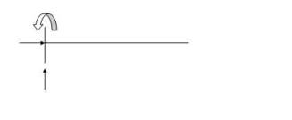 3 3 0
3 3 0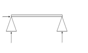 3 3 0
3 3 0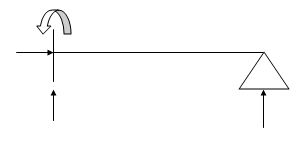 4 3 1
4 3 1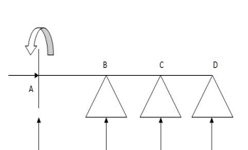 6 3 3
6 3 3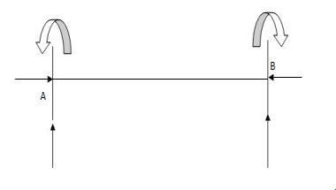 6 3 3
6 3 3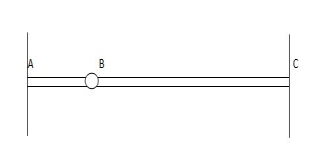 6 4 2
6 4 2
7. 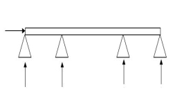 5 4 1
5 4 1
8. 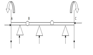 9 5 4
9 5 4
Dsi for Trusses:
(Dsi)Total = (m + R) – (2J)
Where,
M = No of members
R = No of support reactions
J = No of Joints
(Dsi) external = R – 3
(Dsi) internal = (Dsi) total – (Dsi)ext
Dsi = (M + R) – 2j
Sr. No Truss m R J (Dsi)Total
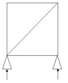 5 3 4 0
2. 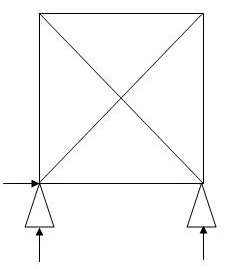 6 3 4 1
(Dsi)int.=0
(Dsi)ext= 1
3. 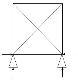 5 4 4 1
(Dsi)int.=1
(Dsi)ext= 0
4. 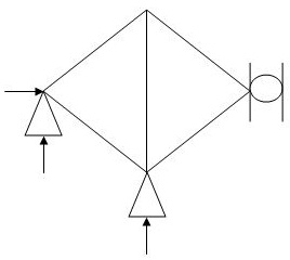 5 4 4 1
(Dsi)int.= 1
(Dsi)ext= 0
5. 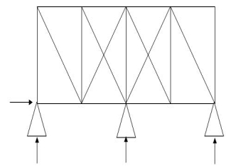 19 4 10 3
(Dsi)int.= 1
(Dsi)ext= 2
6. 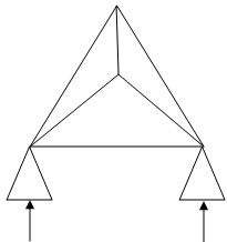 6 4 4 2
(Dsi)int. = 1
(Dsi)ext = 1
7. 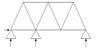 11 4 7 1
(Dsi)int. = 1
(Dsi)ext = 0
8. 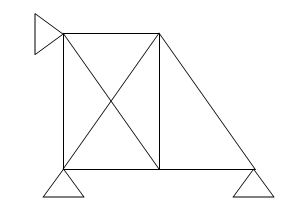 8 4 5 2
(Dsi)int.= 1
(Dsi)ext = 1
9. 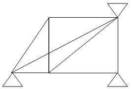 8 5 5 3
(Dsi)int. = 2
(Dsi)ext = 1
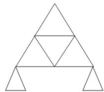
10. 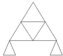 9 3 6 0
1. Concepts – i) Moment at simply supported end is always zero.
Ii) Moment at fixed & intermediate is created
2. Formula:
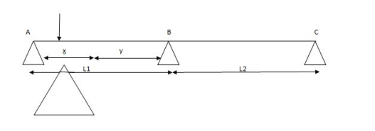
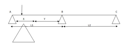
For span ABC
MAl1 + 2MB (l1+l2) + Mcl2 = (6a1x1/l1) + (6a2x2/l2)
For different I -

MAl1 + 2MB (l1+l2) + Mcl2 = (6a1x1/l1) + (6a2x2/l2)
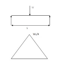
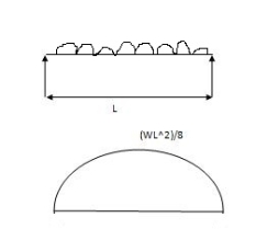
Area due to loading:
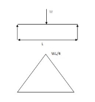
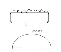
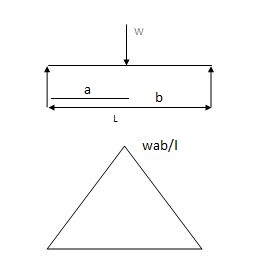
Case (1) both ends are simply supported end
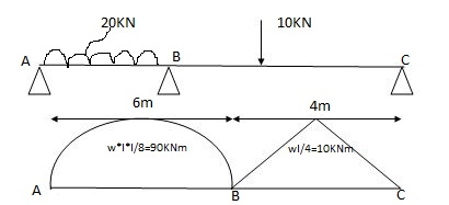
2) 6a1x1 = A = 2 x 6 x 90/3 = 360 A2 = 1 x 4 x 10/3 = 20m2
x1 = 6/2 = 3m x2 = 4/2 = 2m
6a1x1/ l1 = 6 x 360 x 3 / 6 = 1080
6a2x2/l2 = 6 x 20 x 3/4 = 60
1) Apply 3 moments theorem
For span ABC
MAl1 + 2MB (l1+l2) + Mcl2 = 6a1x1/l1 + 6a2x2/l2
MA = MC = 0 l 1=6m l 2 =4m
0 + 2MB (6+4) + 0 = 1080 + 60
2MB (10) = 1140
S.F.D. Due to external load

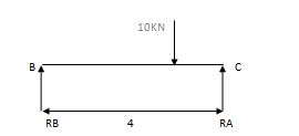
RA = Wl/2 = 20x6/2 = 60 KN RB = W/2 = 10/2 = 5 KN
RB = Wl/2 = 20x6/2 = 60KN RB = W = 10/2 = 5 KN
2) Due to moment

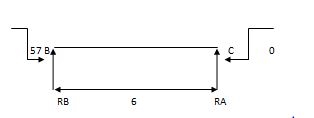
EMA=0 EMB = 0
RB x 6 – 57 = 0 RC x 4 + 57 = 0
RB = 9.5 KN RC = 14.25 KN
Efi = 0
RA + RB = 0 RC + RB = 0
RA = - 9.5 KN RB = 14.25 KN
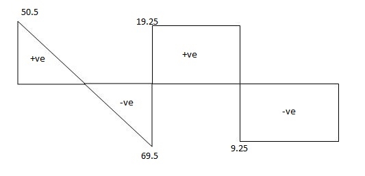
Total reaction:
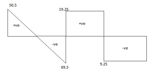
RA = 50.5 KN
RB= 69.5 KN
RC = 5-14.25 = - 9.25 KN
RB = 5 + 14.25 = 19.25 KN

2) One end is fixed & other is Hinge
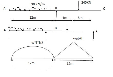
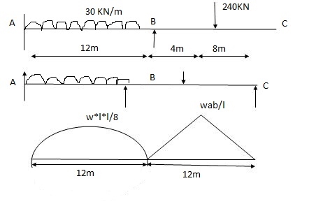
A1 = 2 x wl2 x 12/3 = 2 x 30 x 122 x 12 / 8x3 = 4320 mm2
 = l1/2 = 12 /2 = 6 = 6m
A2 = 1 x Wab x 12/2 = 1 x 240 x 4 x 8 x 12 /12x2 = 3840 mm2
x1 = l2/2 = 12/2 = 6m x1 = L + a/3 x2 = l +b/3

Apply 3 Moment Theorem
A’AB
MA1l1 + 2MA (l1+ l1 ) + MB l1 = 6a1x1 /l1 + 6a1x1/l1
0 + 2MA (0+12) + 12MB = 0 + 6 x 4320 x 6/12
24MA + 12MB = 12960 (1)
Span ABC
MAl1 + 2MB (l1+ l2) + MCl2 = 6a1x1/l1 + 6a2x2/ l2
12MA + 2 MB (12 + 12) + 0 = 6 x 4320 x 6/12 + 6 x 3840 x 6/12
12MA + 48 MB = 24480 (2)
Add eqn. (1) & (2)
MA = 325.71 KNM
MB = 428.57 KNM
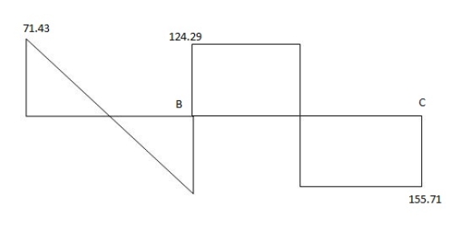
Draw S.F.D.
1) Due to external load

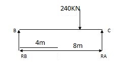
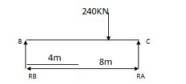
RA = wl/2 = 30 x 12/2 = 180 KNW RB = wb /l = 160 KN
RB = wl/2 = 30 x 12/2 = 180 KN RC = wa =120 KN =
2) Due to moment

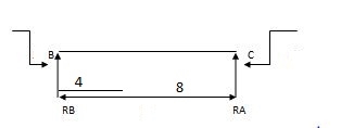
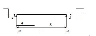
EMA=0 EMB=0
325.71 – 428.57 + RB x 12 = 0 428.57 + RC x 12 = 0
RB = 8.57 RC = 35.71 KN
RA = 8.57 KN RB = 35.71 KN
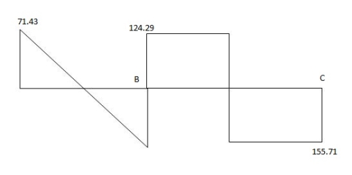
Total Reaction:
RA = 180 – 8.57 = 171.43 KN
RB = 180 + 8.57 = 188.57 KN
RB = 160 + 35.71 = 124.29 KN
RC = 120 + 35.71 = 155.71 KN

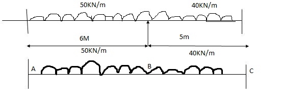
(3) Both ends are fixed

A1 = 0
 = 0
= 0
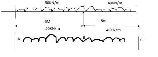
A1 = 2/3 x wl2 /8 x 6 = 112.5 A2 = 2/3 x wl2/8 x 5 = 125
x1 = 6/2 = 3 x2 = 5/2 = 2.5
A12 = 0 x12 = 0
Span A1AB
MAl1+ 2MB (l11 + l1) + MBl1 = 6a11x11/l1 + 6a1x1/l1
0 + 2MA (0+6) + 6MB = 0 + 6 x 112.5 x 3 / 6
12MA + 6MB = 337.5
Span ABC
MAl1+ 2MB (l11 +l1) + MC = 6a1x1/ l1 + 6a2x2/ l2
6MA + 2 MB (6+ 5) + MC x 5 = 6 x 112.5 x 3 /6 + 6 x 175 x 2.5/5
6MA + 22MB + 5MC = 712.5 (2)
Span BCC
MBl2+ 2MC (l2 + l12) + MC1l12 = 6a2x2/ l2 + 6a12x12/ l12
5MB + 2MC (5+0) + 0 = 6 x 125 x 2.5
5MB + 10 MC = 375 (3)
MA = 17.33 KNM
MB = 21.59 KNM
MC = 26.70 KNM
Reaction due to external load


RA = wl/2 = 150 RB = wl /2 = 100 KN
RB = wl /2 = 150 RC = wl /2 = 100 KN
Reaction due to moments


17.33 – 21.59 + RB x 6
RB= 1.022
RB = 0.71 RA = 0.71 RC = 1.022
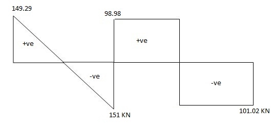
Total Reaction:
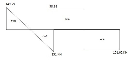
RA = 150 – 0.71 = 149.29 KN
RB = 150 + 0.71 = 150.71 KN
RB = 100 – 1.02 = 98.98 KN
RC = 100 + 1.02 = 101.02 KN

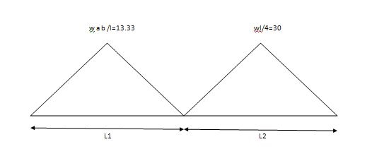
Overhung Numerical:


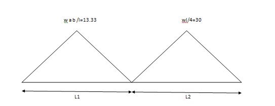
A1 = 1 x 3 x wab/2 A2 = 1/2 x wl /4 x 4
1/2 x 3 x (20 x 1 x 2)/3 = 20m2 A2 = 60 m2
x1 = 4 /3 3 +1/3 = 4/3 = 1.33
Span ABC
MAl1+ 2MB (l1 + l2) + MCl2 = 6a1x1 / l1 + 6a2x2/ l2
0 + 2 MB (3+ 4) + 15 x 4 = 6 x 20 x 1.33/3 + 6 x 60 x 2/4
14MB + 60 = 53.2 + 180
MB = 173.2 KN
Key takeaways
1. Find the reaction
2. Apply three moment theorem
3. Draw SFD
4. Draw BMD
Support settlements can be because of soil erosion, dynamic soil results all through earthquakes, or with the aid of using partial failure or agreement of assisting structural elements. Supports may also probably heave because of frost results (this can be taken into consideration a poor agreement).
For externally determinate systems, assist settlements will genuinely reason an inflexible frame rotation of the shape. Although this motion can be undesirable, the agreement can't reason any inner forces with inside the shape itself. This state of affairs is proven on the pinnacle of Figure. On the opposite hand, for indeterminate systems, agreement of structural helps can set off inner shears and moments as proven with inside the center of Figure. This is due to the fact an indeterminate shape is efficaciously over-constrained, i.e. there are greater restraints than the minimal required for stability.
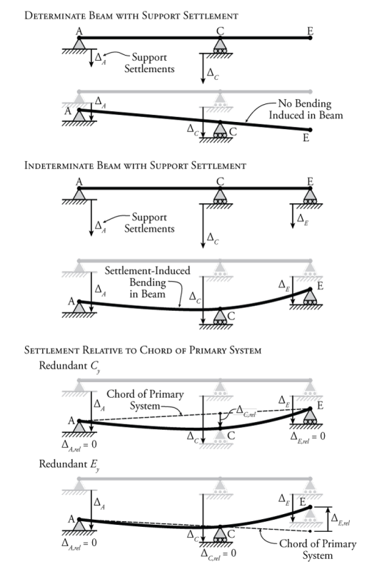
Figure: The Effect of Support Settlement on Indeterminate Beams
In Figure an indeterminate beam is shown that has some support settlement at all three vertical support locations. It seems that the middle support at point C settles rather more than the others. So, this support effectively pulls down on the beam at point C, inducing bending in the beam. Now, of course, since all of the supports are settling to some extent in this example, the support at point C is not pulling down on the beam with a full effective displacement of ΔCΔC relative to the other two supports. It is only the portion of this settlement relative to the other two supports that causes bending in the beam.
We can think of this in terms of a determinate beam with the same geometry as the beam in Figure but with supports only at points A and E. Imaging that there is now some action or load at point C that pulls the beam down at that location, causing bending in the beam. The determinate beam is not affected by the settlement of its supports at A and C, since support settlements do not cause moments in determinate beams as shown at the top of Figure . Instead, we would like to know how much point C moves down, relative to the determinate beam that can rotate freely as a rigid body as A and E settle. We can figure this out by drawing a straight line between points A and E (our determinate beam's unelected shape) and then finding how far support C settles relative to that line.
This is a convenient way to think about things, especially when we are doing a force method analysis. In the force method, we already have a way to temporarily convert an indeterminate system into a determinate system for analysis by considering some of the forces as redundant. The determinate system that remains after we remove the restraints associated with the redundant forces is our primary system.
So, if we now consider the vertical reaction at point C (Cy)to be our redundant force (as shown in Figure), then we can consider our remaining primary system (with supports at A and E) as the determinate system that moves as a rigid body when its supports settle. We can then draw the chord of the primary system, which is just a straight line between points A and E (after they have settled). This chord represents the unreformed shape of the settled determinate primary system. Then, we can find how much the redundant support C has settled relative to the determinate system (ΔC,relΔC,rel). This is the amount of deformation at point C which will cause the beam to bend and deflect.
To consider this relative imposed displacement caused by the support settlement at point C using the force method, all we have to do is modify our compatibility condition. Previously, all of our compatibility conditions typically equated to zero, since we were taking advantage of the compatibility information that a support doesn't move, or that the slope of a member is continuous at a point. For example, for a typical force method analysis where a vertical reaction at C was used as the redundant force, the compatibility condition may have looked something like:
ΔC0+fCCCy=0ΔC0+fCCCy=0
Where ΔC0ΔC0 is the deflection of the primary system at point C due to the external loads, fCC is the deflection of the primary system at point C due to a unit redundant load in that location (in the same direction as the reaction component), and Cy is the reaction component at point C that we are trying to find. The right side of the equation is zero because we know that, typically, a vertical support remains stationary and holds the beam to zero displacement at the support location (i.e. in the real system ΔC=0ΔC=0); however, if we now know that a support does not remain at zero, but actually settles by some known amount, then our compatibility condition will become:
ΔC0+fCCCy=ΔC,rel(1)(1)ΔC0+fCCCy=ΔC,rel
Where ΔC,relΔC,rel is the relative settlement of the reaction at point C relative to the chord of the primary system (as shown in Figure). For the example shown in Figure, if the unit redundant force at point C is assumed to point up, then the magnitude of ΔC,relΔC,rel will be negative, because it settles downward relative to the chord of the primary system. To solve this type of problem, we would have to know the actual magnitude of the settlement at all of the support locations.
For the example in Figure, even though the support settlement is greatest at point C, it does not mean that we must select the reaction at point C as the redundant force for the force method analysis. The diagram at the bottom of the figure shows what would happen if we chose the reaction at point E as the redundant instead. In this case, the primary system is a determinate beam with supports at A and C. This means that the chord of the primary system is a straight line that runs right through these two points as shown. Now, even though the overall settlement of point E was downwards, relative to the chord of the primary system, the support at point E actually pushes the right end of the determinate primary beam up. The resulting compatibility condition for the force method analysis will be:
ΔE0+fEEEy=ΔE,rel(2)(2)ΔE0+fEEEy=ΔE,rel
But this time if the unit redundant is assumed to point up, then the magnitude of ΔE,relΔE,rel will be positive, because the beam heaves up at point E relative to the primary system.
This method also works with force method analyses for structures that are indeterminate to multiple degrees (that have multiple redundant forces). Two different example structures are shown in Figure. The structure shown at the top of that figure is a 2∘2∘ indeterminate propped cantilever and the structure shown at the bottom is a 2∘2∘ indeterminate multi-span beam.
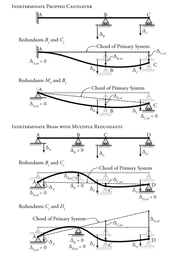
Figure: Selection of the Redundant Force in Force Method Analyses for Structures with Support Settlement
For the instance in Figure, despite the fact that the assist agreement is best at factor C, it does now no longer suggest that we should choose the response at factor C because the redundant pressure for the pressure approach evaluation.
The diagram at the lowest of the determine suggests what might show up if we selected the response at factor E because the redundant instead. In this situation, the number one device is a determinate beam with helps at A and C. This method that the chord of the number one device is a instantly line that runs proper via those factors as proven.
Now, despite the fact that the general agreement of factor E became downwards, relative to the chord of the number one device, the assist at factor E certainly pushes the proper cease of the determinate number one beam up.
The ensuing compatibility situation for the pressure approach evaluation can be: ΔE0+fEEEy=ΔE,rel(2) however this time if the unit redundant is thought to factor up, then the significance of ΔE,rel can be positive, due to the fact the beam heaves up at factor E relative to the number one device. This approach additionally works with pressure approach analyses for systems which are indeterminate to a couple of degrees (which have a couple of redundant forces). Two exclusive instance systems are proven in Figure. The shape proven on the pinnacle of that determine is a 2∘ indeterminate propped cantilever and the shape proven at the lowest is a 2∘ indeterminate multi-span beam.
For the indeterminate propped cantilever in Figure, there are exclusive units of viable redundant forces proven. If the vertical reactions at factors B and C (By and Cy) are used because the redundant forces, then the number one device is a easy cantilever with a set cease at factor A.
So the chord of the number one device is genuinely a horizontal line that follows the unreformed form of the shape. In this situation the relative settlements of helps B and C are genuinely same to the entire agreement significance (ΔB,rel=ΔB and ΔC,rel=ΔC). The compatibility situations for this evaluation can be:
ΔB0+fBBBy+fBCCyΔC0+fCBBy+fCCCy=ΔB,
Since no outside hundreds are supplied for this instance, ΔB0 and ΔC0 might be same to 0. If the instant response at factor A and the vertical response at factor B (MA and By) are used because the redundant forces, then the ensuing determinate number one device is a genuinely supported beam among factors A and C. This beam stories a inflexible frame rotation because of the assist agreement at factor C, ensuing with inside the chord for the number one device proven in Figure 8.24. Using the geometry of the device, we should then locate the fee of ΔB, reel primarily based totally at the place of the chord at factor
B.θA0+fAAMA+fABByΔB0+fBAMA+fBBBy=0=ΔB,
Again, because no outside hundreds are supplied for this instance, θA0 and ΔB0 might be same to 0. Note that the proper aspect of the primary compatibility equation remains 0, due to the fact the rotation of the entire device at factor a remains recognized to be 0.
Key Takeaways:
- The diagram at the bottom of the figure shows what would happen if we chose the reaction at point E as the redundant instead. In this case, the primary system is a determinate beam with supports at A and C.
- This method that the chord of the number one device is a instantly line that runs proper via those factors as proven.
- Two exclusive instance systems are proven in Figure 8.24. The shape proven on the pinnacle of that determine is a 2∘ indeterminate propped cantilever and the shape proven at the lowest is a 2∘ indeterminate multi-span beam.
References:
1. Structural Analysis by C.S. Reddy Mc. Graw Hill
2. Structural Analysis by R.C. Hibbler Pearson Education
Unit - 1
Introduction of Statically indeterminate Structures
Static Indeterminacy:
The Static Indeterminacy (SI) for beams and frames is described as,
SI = nu — ne
Where,
nu = Number of unknown assist reactions
ne = Number of equations of equilibrium
In fashionable for a -dimensional shape, there are 3 equations of equilibrium (ne = 3) and for a 3-dimensional shape there are six (ne = 6).
For a truss, static indeterminacy entails each outside and inner indeterminacy due to the inner individuals in a truss.
Static indeterminacy (SI) within side the case of a truss is described as,
SI = b + r — 2j
Where,
b = Number of individuals within side the truss
r = Number of reactions on the supports
j = Number of joints within side the truss
Sign Conventions
1). Static Calculations
∑F x = 0, ∑F y = 0 & ∑M = 0
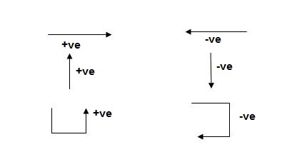
For Structural Actions
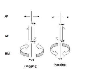
Degree of static indeterminacy (Dsi)
Dsi = No of Unknown Actions –No of Eqn,
Dsi = R – E
External Indeterminacy
When we can't discover assist reactions the use of legal guidelines at statics, its miles referred to as externally indeterminate structure.
Internal Indeterminacy
When we can't discover inner member movements the use of legal guidelines of statics, its miles referred to as internally indeterminate structure.
Boundary condition
Displacement Re stained Displacement allow
Δx, Δy, ϴz Nil
Δy,ϴz, Δx
Δx, Δyϴz
Dsi for beams = R – E
Where,
R = No of assist reactions
E = No of Equilibrium equations
Note: For one inner pin, no of extra equations of equilibrium are = m – 1
m = no of individuals linked via way of means of pin.
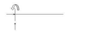
Sr. No Structure R E Dsi
 3 3 0
3 3 0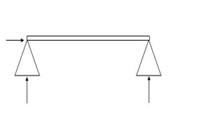 3 3 0
3 3 0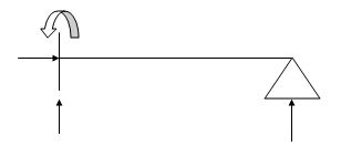 4 3 1
4 3 1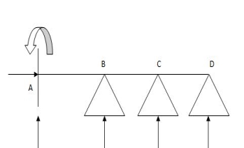 6 3 3
6 3 3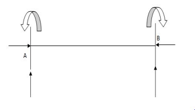 6 3 3
6 3 3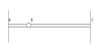 6 4 2
6 4 2
7. 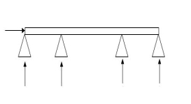 5 4 1
5 4 1
8. 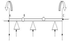 9 5 4
9 5 4
Dsi for Trusses:
(Dsi)Total = (m + R) – (2J)
Where,
M = No of members
R = No of support reactions
J = No of Joints
(Dsi) external = R – 3
(Dsi) internal = (Dsi) total – (Dsi)ext
Dsi = (M + R) – 2j
Sr. No Truss m R J (Dsi)Total
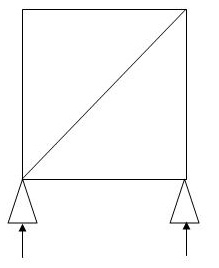 5 3 4 0
2. 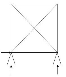 6 3 4 1
(Dsi)int.=0
(Dsi)ext= 1
3. 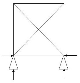 5 4 4 1
(Dsi)int.=1
(Dsi)ext= 0
4. 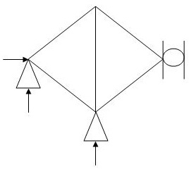 5 4 4 1
(Dsi)int.= 1
(Dsi)ext= 0
5. 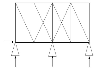 19 4 10 3
(Dsi)int.= 1
(Dsi)ext= 2
6. 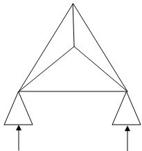 6 4 4 2
(Dsi)int. = 1
(Dsi)ext = 1
7. 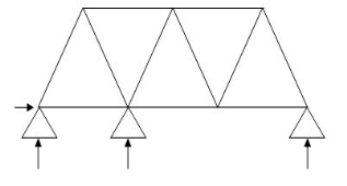 11 4 7 1
(Dsi)int. = 1
(Dsi)ext = 0
8. 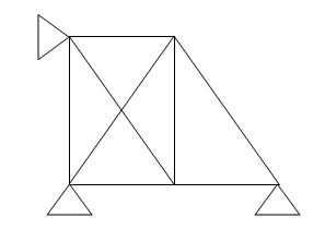 8 4 5 2
(Dsi)int.= 1
(Dsi)ext = 1
9. 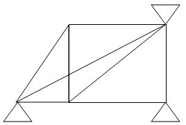 8 5 5 3
(Dsi)int. = 2
(Dsi)ext = 1
10.  9 3 6 0
1. Concepts – i) Moment at simply supported end is always zero.
Ii) Moment at fixed & intermediate is created
2. Formula:
For span ABC
MAl1 + 2MB (l1+l2) + Mcl2 = (6a1x1/l1) + (6a2x2/l2)
For different I -

MAl1 + 2MB (l1+l2) + Mcl2 = (6a1x1/l1) + (6a2x2/l2)
Area due to loading:
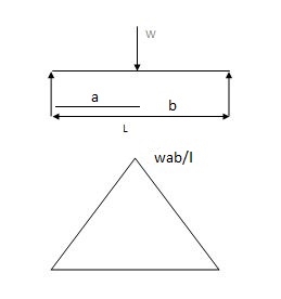
Case (1) both ends are simply supported end
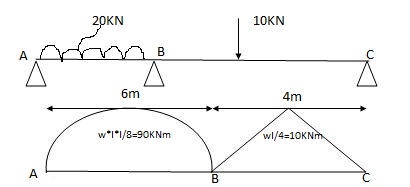
2) 6a1x1 = A = 2 x 6 x 90/3 = 360 A2 = 1 x 4 x 10/3 = 20m2
x1 = 6/2 = 3m x2 = 4/2 = 2m
6a1x1/ l1 = 6 x 360 x 3 / 6 = 1080
6a2x2/l2 = 6 x 20 x 3/4 = 60
1) Apply 3 moments theorem
For span ABC
MAl1 + 2MB (l1+l2) + Mcl2 = 6a1x1/l1 + 6a2x2/l2
MA = MC = 0 l 1=6m l 2 =4m
0 + 2MB (6+4) + 0 = 1080 + 60
2MB (10) = 1140
S.F.D. Due to external load

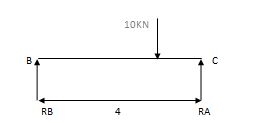
RA = Wl/2 = 20x6/2 = 60 KN RB = W/2 = 10/2 = 5 KN
RB = Wl/2 = 20x6/2 = 60KN RB = W = 10/2 = 5 KN
2) Due to moment

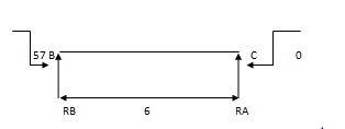
EMA=0 EMB = 0
RB x 6 – 57 = 0 RC x 4 + 57 = 0
RB = 9.5 KN RC = 14.25 KN
Efi = 0
RA + RB = 0 RC + RB = 0
RA = - 9.5 KN RB = 14.25 KN
Total reaction:
RA = 50.5 KN
RB= 69.5 KN
RC = 5-14.25 = - 9.25 KN
RB = 5 + 14.25 = 19.25 KN

2) One end is fixed & other is Hinge
A1 = 2 x wl2 x 12/3 = 2 x 30 x 122 x 12 / 8x3 = 4320 mm2
 = l1/2 = 12 /2 = 6 = 6m
A2 = 1 x Wab x 12/2 = 1 x 240 x 4 x 8 x 12 /12x2 = 3840 mm2
x1 = l2/2 = 12/2 = 6m x1 = L + a/3 x2 = l +b/3

Apply 3 Moment Theorem
A’AB
MA1l1 + 2MA (l1+ l1 ) + MB l1 = 6a1x1 /l1 + 6a1x1/l1
0 + 2MA (0+12) + 12MB = 0 + 6 x 4320 x 6/12
24MA + 12MB = 12960 (1)
Span ABC
MAl1 + 2MB (l1+ l2) + MCl2 = 6a1x1/l1 + 6a2x2/ l2
12MA + 2 MB (12 + 12) + 0 = 6 x 4320 x 6/12 + 6 x 3840 x 6/12
12MA + 48 MB = 24480 (2)
Add eqn. (1) & (2)
MA = 325.71 KNM
MB = 428.57 KNM
Draw S.F.D.
1) Due to external load

RA = wl/2 = 30 x 12/2 = 180 KNW RB = wb /l = 160 KN
RB = wl/2 = 30 x 12/2 = 180 KN RC = wa =120 KN =
2) Due to moment

EMA=0 EMB=0
325.71 – 428.57 + RB x 12 = 0 428.57 + RC x 12 = 0
RB = 8.57 RC = 35.71 KN
RA = 8.57 KN RB = 35.71 KN
Total Reaction:
RA = 180 – 8.57 = 171.43 KN
RB = 180 + 8.57 = 188.57 KN
RB = 160 + 35.71 = 124.29 KN
RC = 120 + 35.71 = 155.71 KN

(3) Both ends are fixed

A1 = 0
 = 0
= 0
A1 = 2/3 x wl2 /8 x 6 = 112.5 A2 = 2/3 x wl2/8 x 5 = 125
x1 = 6/2 = 3 x2 = 5/2 = 2.5
A12 = 0 x12 = 0
Span A1AB
MAl1+ 2MB (l11 + l1) + MBl1 = 6a11x11/l1 + 6a1x1/l1
0 + 2MA (0+6) + 6MB = 0 + 6 x 112.5 x 3 / 6
12MA + 6MB = 337.5
Span ABC
MAl1+ 2MB (l11 +l1) + MC = 6a1x1/ l1 + 6a2x2/ l2
6MA + 2 MB (6+ 5) + MC x 5 = 6 x 112.5 x 3 /6 + 6 x 175 x 2.5/5
6MA + 22MB + 5MC = 712.5 (2)
Span BCC
MBl2+ 2MC (l2 + l12) + MC1l12 = 6a2x2/ l2 + 6a12x12/ l12
5MB + 2MC (5+0) + 0 = 6 x 125 x 2.5
5MB + 10 MC = 375 (3)
MA = 17.33 KNM
MB = 21.59 KNM
MC = 26.70 KNM
Reaction due to external load


RA = wl/2 = 150 RB = wl /2 = 100 KN
RB = wl /2 = 150 RC = wl /2 = 100 KN
Reaction due to moments


17.33 – 21.59 + RB x 6
RB= 1.022
RB = 0.71 RA = 0.71 RC = 1.022
Total Reaction:
RA = 150 – 0.71 = 149.29 KN
RB = 150 + 0.71 = 150.71 KN
RB = 100 – 1.02 = 98.98 KN
RC = 100 + 1.02 = 101.02 KN

Overhung Numerical:


A1 = 1 x 3 x wab/2 A2 = 1/2 x wl /4 x 4
1/2 x 3 x (20 x 1 x 2)/3 = 20m2 A2 = 60 m2
x1 = 4 /3 3 +1/3 = 4/3 = 1.33
Span ABC
MAl1+ 2MB (l1 + l2) + MCl2 = 6a1x1 / l1 + 6a2x2/ l2
0 + 2 MB (3+ 4) + 15 x 4 = 6 x 20 x 1.33/3 + 6 x 60 x 2/4
14MB + 60 = 53.2 + 180
MB = 173.2 KN
Key takeaways
1. Find the reaction
2. Apply three moment theorem
3. Draw SFD
4. Draw BMD
Support settlements can be because of soil erosion, dynamic soil results all through earthquakes, or with the aid of using partial failure or agreement of assisting structural elements. Supports may also probably heave because of frost results (this can be taken into consideration a poor agreement).
For externally determinate systems, assist settlements will genuinely reason an inflexible frame rotation of the shape. Although this motion can be undesirable, the agreement can't reason any inner forces with inside the shape itself. This state of affairs is proven on the pinnacle of Figure. On the opposite hand, for indeterminate systems, agreement of structural helps can set off inner shears and moments as proven with inside the center of Figure. This is due to the fact an indeterminate shape is efficaciously over-constrained, i.e. there are greater restraints than the minimal required for stability.
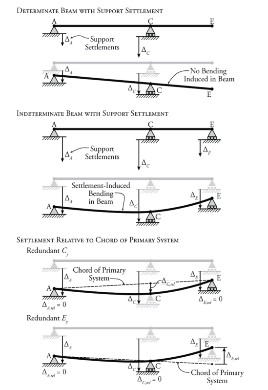
Figure: The Effect of Support Settlement on Indeterminate Beams
In Figure an indeterminate beam is shown that has some support settlement at all three vertical support locations. It seems that the middle support at point C settles rather more than the others. So, this support effectively pulls down on the beam at point C, inducing bending in the beam. Now, of course, since all of the supports are settling to some extent in this example, the support at point C is not pulling down on the beam with a full effective displacement of ΔCΔC relative to the other two supports. It is only the portion of this settlement relative to the other two supports that causes bending in the beam.
We can think of this in terms of a determinate beam with the same geometry as the beam in Figure but with supports only at points A and E. Imaging that there is now some action or load at point C that pulls the beam down at that location, causing bending in the beam. The determinate beam is not affected by the settlement of its supports at A and C, since support settlements do not cause moments in determinate beams as shown at the top of Figure . Instead, we would like to know how much point C moves down, relative to the determinate beam that can rotate freely as a rigid body as A and E settle. We can figure this out by drawing a straight line between points A and E (our determinate beam's unelected shape) and then finding how far support C settles relative to that line.
This is a convenient way to think about things, especially when we are doing a force method analysis. In the force method, we already have a way to temporarily convert an indeterminate system into a determinate system for analysis by considering some of the forces as redundant. The determinate system that remains after we remove the restraints associated with the redundant forces is our primary system.
So, if we now consider the vertical reaction at point C (Cy)to be our redundant force (as shown in Figure), then we can consider our remaining primary system (with supports at A and E) as the determinate system that moves as a rigid body when its supports settle. We can then draw the chord of the primary system, which is just a straight line between points A and E (after they have settled). This chord represents the unreformed shape of the settled determinate primary system. Then, we can find how much the redundant support C has settled relative to the determinate system (ΔC,relΔC,rel). This is the amount of deformation at point C which will cause the beam to bend and deflect.
To consider this relative imposed displacement caused by the support settlement at point C using the force method, all we have to do is modify our compatibility condition. Previously, all of our compatibility conditions typically equated to zero, since we were taking advantage of the compatibility information that a support doesn't move, or that the slope of a member is continuous at a point. For example, for a typical force method analysis where a vertical reaction at C was used as the redundant force, the compatibility condition may have looked something like:
ΔC0+fCCCy=0ΔC0+fCCCy=0
Where ΔC0ΔC0 is the deflection of the primary system at point C due to the external loads, fCC is the deflection of the primary system at point C due to a unit redundant load in that location (in the same direction as the reaction component), and Cy is the reaction component at point C that we are trying to find. The right side of the equation is zero because we know that, typically, a vertical support remains stationary and holds the beam to zero displacement at the support location (i.e. in the real system ΔC=0ΔC=0); however, if we now know that a support does not remain at zero, but actually settles by some known amount, then our compatibility condition will become:
ΔC0+fCCCy=ΔC,rel(1)(1)ΔC0+fCCCy=ΔC,rel
Where ΔC,relΔC,rel is the relative settlement of the reaction at point C relative to the chord of the primary system (as shown in Figure). For the example shown in Figure, if the unit redundant force at point C is assumed to point up, then the magnitude of ΔC,relΔC,rel will be negative, because it settles downward relative to the chord of the primary system. To solve this type of problem, we would have to know the actual magnitude of the settlement at all of the support locations.
For the example in Figure, even though the support settlement is greatest at point C, it does not mean that we must select the reaction at point C as the redundant force for the force method analysis. The diagram at the bottom of the figure shows what would happen if we chose the reaction at point E as the redundant instead. In this case, the primary system is a determinate beam with supports at A and C. This means that the chord of the primary system is a straight line that runs right through these two points as shown. Now, even though the overall settlement of point E was downwards, relative to the chord of the primary system, the support at point E actually pushes the right end of the determinate primary beam up. The resulting compatibility condition for the force method analysis will be:
ΔE0+fEEEy=ΔE,rel(2)(2)ΔE0+fEEEy=ΔE,rel
But this time if the unit redundant is assumed to point up, then the magnitude of ΔE,relΔE,rel will be positive, because the beam heaves up at point E relative to the primary system.
This method also works with force method analyses for structures that are indeterminate to multiple degrees (that have multiple redundant forces). Two different example structures are shown in Figure. The structure shown at the top of that figure is a 2∘2∘ indeterminate propped cantilever and the structure shown at the bottom is a 2∘2∘ indeterminate multi-span beam.
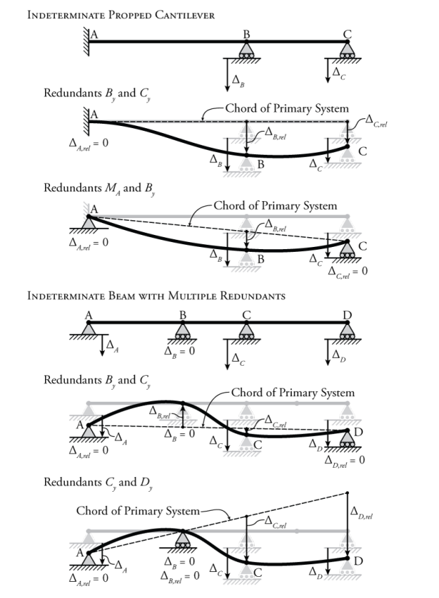
Figure: Selection of the Redundant Force in Force Method Analyses for Structures with Support Settlement
For the instance in Figure, despite the fact that the assist agreement is best at factor C, it does now no longer suggest that we should choose the response at factor C because the redundant pressure for the pressure approach evaluation.
The diagram at the lowest of the determine suggests what might show up if we selected the response at factor E because the redundant instead. In this situation, the number one device is a determinate beam with helps at A and C. This method that the chord of the number one device is a instantly line that runs proper via those factors as proven.
Now, despite the fact that the general agreement of factor E became downwards, relative to the chord of the number one device, the assist at factor E certainly pushes the proper cease of the determinate number one beam up.
The ensuing compatibility situation for the pressure approach evaluation can be: ΔE0+fEEEy=ΔE,rel(2) however this time if the unit redundant is thought to factor up, then the significance of ΔE,rel can be positive, due to the fact the beam heaves up at factor E relative to the number one device. This approach additionally works with pressure approach analyses for systems which are indeterminate to a couple of degrees (which have a couple of redundant forces). Two exclusive instance systems are proven in Figure. The shape proven on the pinnacle of that determine is a 2∘ indeterminate propped cantilever and the shape proven at the lowest is a 2∘ indeterminate multi-span beam.
For the indeterminate propped cantilever in Figure, there are exclusive units of viable redundant forces proven. If the vertical reactions at factors B and C (By and Cy) are used because the redundant forces, then the number one device is a easy cantilever with a set cease at factor A.
So the chord of the number one device is genuinely a horizontal line that follows the unreformed form of the shape. In this situation the relative settlements of helps B and C are genuinely same to the entire agreement significance (ΔB,rel=ΔB and ΔC,rel=ΔC). The compatibility situations for this evaluation can be:
ΔB0+fBBBy+fBCCyΔC0+fCBBy+fCCCy=ΔB,
Since no outside hundreds are supplied for this instance, ΔB0 and ΔC0 might be same to 0. If the instant response at factor A and the vertical response at factor B (MA and By) are used because the redundant forces, then the ensuing determinate number one device is a genuinely supported beam among factors A and C. This beam stories a inflexible frame rotation because of the assist agreement at factor C, ensuing with inside the chord for the number one device proven in Figure 8.24. Using the geometry of the device, we should then locate the fee of ΔB, reel primarily based totally at the place of the chord at factor
B.θA0+fAAMA+fABByΔB0+fBAMA+fBBBy=0=ΔB,
Again, because no outside hundreds are supplied for this instance, θA0 and ΔB0 might be same to 0. Note that the proper aspect of the primary compatibility equation remains 0, due to the fact the rotation of the entire device at factor a remains recognized to be 0.
Key Takeaways:
- The diagram at the bottom of the figure shows what would happen if we chose the reaction at point E as the redundant instead. In this case, the primary system is a determinate beam with supports at A and C.
- This method that the chord of the number one device is a instantly line that runs proper via those factors as proven.
- Two exclusive instance systems are proven in Figure 8.24. The shape proven on the pinnacle of that determine is a 2∘ indeterminate propped cantilever and the shape proven at the lowest is a 2∘ indeterminate multi-span beam.
References:
1. Structural Analysis by C.S. Reddy Mc. Graw Hill
2. Structural Analysis by R.C. Hibbler Pearson Education