Unit - 3
Strain energy method
1. Strain Energy method
Q.1) EI = 17250 Kn.m2 find strain energy?
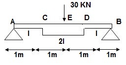
Solution:
∑MA = 0
30 x 2 – RB x 4 = 0
RB = 15
VA = VB = 15 KN
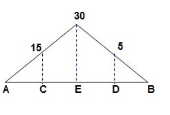
BMC = BMD = 15(1) = 15 KN.M
BMC = 15(2) = 30 KN.M
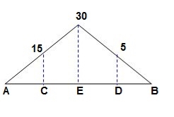
‘M/EI’ Dia.
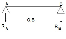
C.B
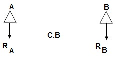
A1 = 1 / 2 x 1 x 15/EI = 7.5/EI
A2 = 2 x 7.5/EI = 15/EI
A3 = 1 /2 x 2 x 7.5/EI = 7.5/EI
A4 = 1 / 2 x 15/EI x 1 = 7.5/EI
Analysis of conjugate beam:
∑MA = -RB (4) + 1/EI {7.5(2/3 x 1) + 15(2) + 7.5(2) + 7.5(3 + 1/31)} = 0
= - RB x 4 + 1/ EI [5 + 30 + 15 + 25 ] = 0
RB x 4 = 75/17250
RB = 18.75/EI
∑fy = 0
-RA + RB + A1 + A2 + A3 + A4 = 0
RA = 18.75/EI
RA = RB = ½{A1 + A2 + A3 + A4} = 18.75/EI
Slope & Deflection:
(ϴA)R.B = (SFA)C.B = (-)18.75/EI
= 18.75/EI  = 1.086 x 10⁻³rad
(ϴB)R.B = (SFB)C.B = 18.75/EI = 1.086 x 10⁻³ rad
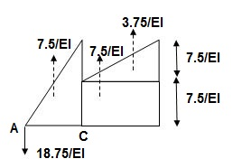
(ΔE)R.B = (BME)CB
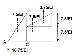
(BME)CB= 1/ EI { -18.75 + 7.5(1 + 1/3 x 1) + 7.5(0.5) + 3.75 (1/3 x 1)}
=1/ EI {-22.5}
ΔE = 22.5/EI  = 1.304 mm
Key takeaways
1. Find Reactions
2. M/EI Diagram
3. C.B
4. Analysis of Conjugate Beam
5. Slope and Deflection
Unit load method for statically determinate beams, frames and trusses
The unit load method helps us in finding the displacement D, at the coordinate in a structure, whose deformations are either known or can be derived. In just-rigid structures, the internal displacement field is generally known in problems of indirect loading, such as due to environmental effects and constructional errors ("lack of fit' in trusses), and it is desired to find a joint displacement that is compatible with the deformation. More commonly, we encounter problems involving direct actions, where the deformations are not given, but can be derived from the internal force response. For example, we can calculate bar elongations in truss members, if we know the axial forces in the bars. Similarly, from the bending moment distribution in flexural members, we can derive the curvatures.
Assuming linear elastic behavior (we have the following well known relationships:
(a) Between bar elongation e, and axial force N, in a truss member (having an axial rigidity EA and length L)

Where, the subscript i refer to the i bar (truss element), whose axial flexibility f, is given by

(b) Between curvature  - (having flexural rigidity(El) de and bending moment M(x) in a flexural member

Application of trusses
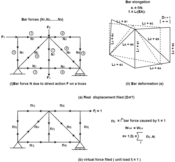
Consider a truss with some (real) displacement field, which may be caused by direct or indirect loading. The elongation e in all the bars are known and it is desired to find some joint displacement D, at the coordinate. If the cause is loading by direct actions, the bar forces N, can be analyzed and the corresponding bar elongations e, are easily obtainable by applying Eq. This is depicted in Fig. If the cause is due to lack of fit or temperature change, and the truss is just-rigid, the values of e, are known.
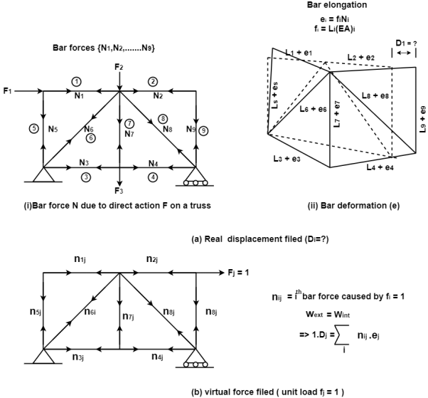
Now, consider the same truss and apply a virtual unit load, F= 1 at the coordinate as shown in Fig. Analyze the truss and arrive at all the virtual bar forces n. The force in the bar may be denoted as nij, i.e, caused by unit load applied at j.
Combining the real and virtual force fields shown in Fig. We can write the expressions for virtual work:
External work

Internal work

Applying the Principle of virtual work,


Note that D, has the same unit (dimension) as e, (usually in mm). Is dimensionally homogeneous because the bar force n (caused by a unit load) is dimensionless, having units of kN
Application to Beams and Frames
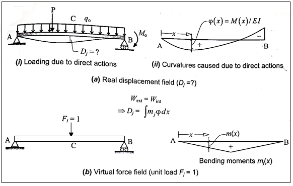
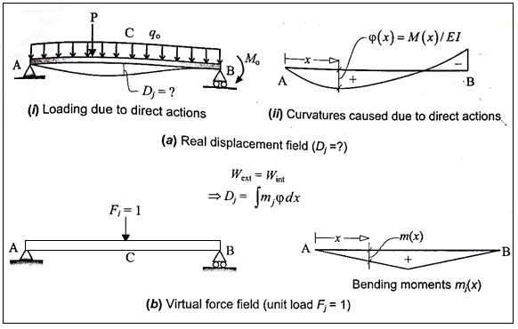
Consider a beam with some (real) displacement field, which may be caused by direct or indirect loading. The variation of curvature p(x) along the length of the beam is known and it is desired to find a deflection or a rotation DJ at the coordinate. If the cause is loading by direct actions, the bending moments M(x) can be analyzed, and the corresponding curvatures P(x) are easily obtainable by applying Eq. This is depicted in Fig. If the cause is due to indirect loading (such as due to differential shrinkage in a reinforced concrete beam), the distribution of curvatures should be known
Now, consider the same beam and apply a virtual unit load F-1 as shown in Fig... Analyze the beam and arrive at the bending moment’s m(x).
Combining the real and virtual force fields shown in Fig. We can write the expressions for virtual work:
External work

Internal work

Applying the principle of virtual work

Examples
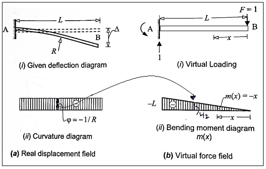
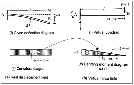
Q. 1 considering a cantilever beam length L bent to a segment of a circle of radius R. Find the deflection at the free end.
Solution:
The curvature length as given in beam in constant with  as shown in fig
Applying the principle of virtual work


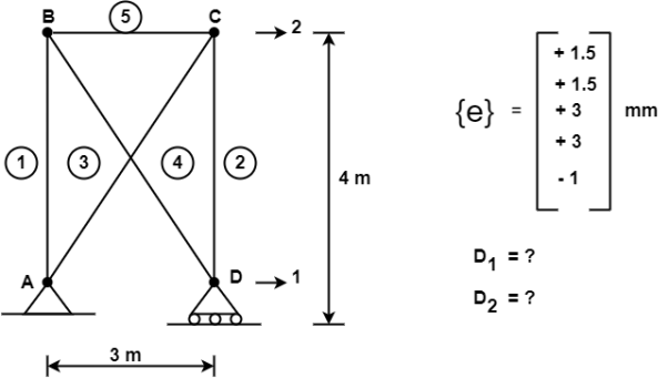
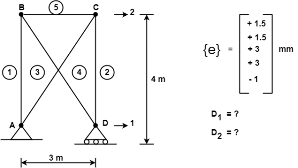
Q.2 Consider the pin jointed truss in fig. With bars numbered as indicated. Due to certain environmental change bar 1 and 2 increase in length by 1.5 mm bars 3 and 4 increases in length by 3 mm and bar 5 reduce in length by 1 mm find the horizontal movement of i th the roller support at D and the joint C
Solution:
The bar elongations gives form part of a real displacement filed with
{e} = { +1.5,+1.5.+3,+3,-1}^T mm
The required horizontal joint displacement at D and C are identified as Di and Dj resp. Using the coordinate system in shown in fig.
Applying unit load method


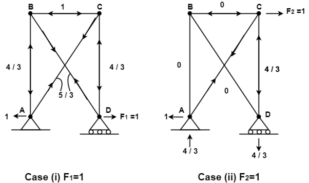
Where ni1 and ni2 are the force the i the bar due to F1 = 1 and F2 = 1


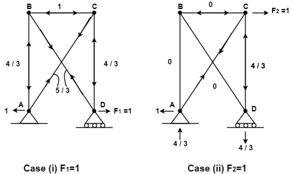
Therefore the horizontal movement at the roller support is given by
Case 1 Horizontal deflection D1 of the support D


Case 2 Horizontal deflection D2 of a joint C


1) Determine deflection of trust joint
1) Determine P force by given load system using joint method.
2) Remove given loud system & apply unit load to joint where the deflection desired find K force.
3) Determine PKl/ AI of each member
4) Deflection of the joint = ∑ PKl / AE
2) Analysis of indeterminate plane truss
1) Find the degree of indeterminacy
2) Select redundant member
3) Remove redundant member and find the force P in the members of the truss.
4) Remove the given loud system
a) Apply a unit load paid (either textile/ amp) in place of redundant member.
b) Find k force.
5) PKl / AE & K2L / AE
6) Correction factor = x = ∑ PKl / AE P = (P + KX) / ∑ K2L/ AE
Lock of fit of members in trust
Lock of fit is defined as little or little shorter length of any in trust.
Correction factor due to lack of
x = x (- ∑ PKl / AE) / (∑ K2L/ AE)
Where
x = shortening or excess of members
+ve = if member is short in length
-ve = if member is short in long
Find force = f = P + Kx
Formula for truss
1) Find detection -


2) Analyze indeterminate
i) F = P + KX x = (∑PKl/AE) / (∑K2l/AE)
Ii) For lock of fit =
Sign convention -ve for short member
+ve for long member
Iii) for Temp effect P = QK
Q = (xlt) / ∑ K2l/AE
Iv) for yield support
F = P + QK
DQ = DQL + FQ
DQ = Sink
DQL = ∑ PKl / AE
F = ∑ K2l / AE
2)
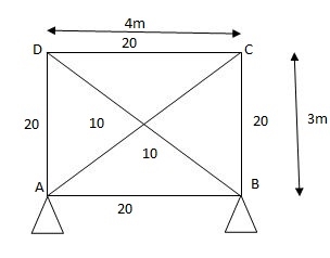
AD in short by
E = 200 Gpa
FAB = 28.04 KN FOC = 21.08
FOD = 28.04 KN FDA = 21.28
FDB = 35./20 KN FAC = 30.
1) Analyze the truss supported as shown in fig. If member AD is subjected to temp drop of 300C Taken E= 200 Gpa & coeff. Thermal expansion = 1.1 x 10⁻⁵/oc C/S area of each member in cm2 is indicated in brackets.
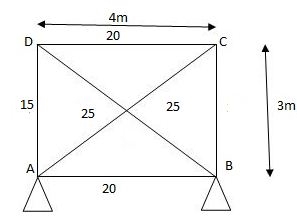
Given:
AD is subjected to Temp drop 300C.
AD is redundant member consist unit load due to drop -ve sign
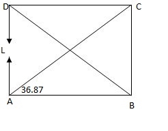
Joint A
Efy = 0
KAC5in 36.86 + 1 = 0
KAC = - 1.67 KN
Efx = 0
KAB + KAC COS 36.86 = 0
KAB = 1.34 KN
Joint D
Efy = 0
KDBsin 36.86 – 1 = 0
KDB = - 1.67 KDC = 1.33
Sr. No. | Member | Length | Area | K | …. | Q | …. |
AB |
| 4000 | 2000 | 1.33 | 3.56 |
| 11.84 |
BC |
| 3000 | 1000 | 1 | 2 |
| 8.9 |
CD |
| 4000 | 2000 | 1.33 | 3.56 | 8.9 | 11.84 |
DA |
| 3000 | 1000 | 1 | 5.56 |
| 8.90 |
DB |
| 5000 | 2000 | - 1.67 | 5.56 |
| -14.86 |
AC |
| 5000 | 2000 | - 1.67 | 2 |
| -14.86 |
P = QK

P = 8.90 x K
C/s area 10m2, rise of kmp of member BD by 300c
= 12 x 10-6 /oc E= 200Gpa.
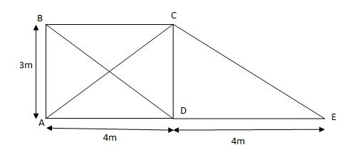
FBC = 17.77KN, FCD = 13.33 KN FAD = 12.77KN
FAC = 22.22 KN FBD = 22.22 KN FDE = FCE = 0
Effects of yielding of support in determine trusses
2) Analyze the truss supported as shown in fig., if support B sink by 3mm & c/s area of each member 400mm2.
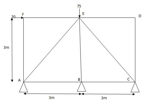
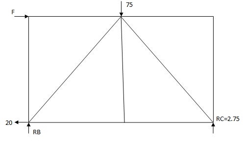
Joint A
Efx = 0
PAB + PAE COS45 – 20 = 0
PAB + PAECOS45 – 20 (1)
Efy = 0
PAESin45 – PAF + ……. = 0
PAE = 38.89 KN
PAB + - 38.89 ……… = 20
PAB = 47.49 …
Joint B
Efx = 0
- PBA + PBC = 0
PBC = 47.49 KN
PEB = 0KN
Find k force
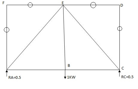
By observation
Joint A
Efx = 0
KAB + KAE COS45 = 0
KAE Sin45 + 0.5 = 0
KAE = - 0.707
KAB = - 0.49
Sr.No. | Member | Length | P | K | PK8 | P2B | F= P+ |
1. | AB | 3000 | 47.5 | -0.5 | -23.75 | + 0.25 | 76.1 |
2. | BC | 3000 | 47.5 | -0.5 | -23.75 | + 0.25 |
|
3. | CD | 3000 | 0 | 0 | 0 | 0 |
|
4. | DE | 3000 | -20 | 0 | 0 | 0 |
|
5. | EF | 3000 | -20 | 0 | 0 | 0 |
|
6. | AE | 3000 | -38.89 | -0.707 | 24.5 | 0.49 |
|
7. | EC | 3000 | -38.89 | -0.707 | 24.5 | 0.49 |
|
8. | BE | 3000 | 0 | 1 | 0 | 0 |
|
9. | AF | 4242.6 | 0 | 0 | 0 | 0 |
|
|
|
|
| E | 4500 | 1.49 X 3000 = 4440 | |
DQ = DQL + FQ
DQ1 = EPKl / AC = 0.053
F= EK2l / AE = 0.0528
DQ = 3mm
Indeterminate trusses with lack of f/f
DQ = DQF + FQ DQ = O
Q = - DQF/ K2L /AE F =K2L
DQF is +ve if the member is long
DQF is -ve if the member is short
3) Analyze the truss supported as show in fig. If the member AB is short by 5mm Take E= 200 Gpa c/s area of each member in is indicated in brackets.
AB = 5mm short consider -ve sign
E = 200 Gpa
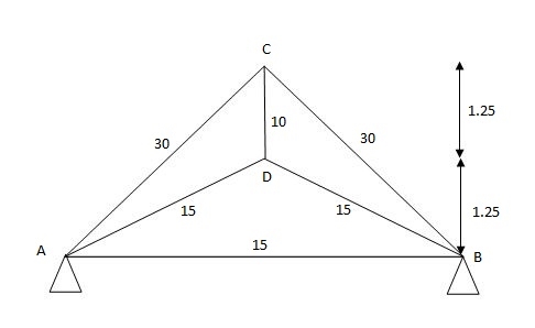
1cm = 10mm
1m = 103mm
Sr.No. | Member | Length | Area | K | K2l |
1. | AD | 2795 | 1500 | 2.23 | 9.35 |
2. | BD | 2795 | 1500 | 2.23 | 9.35 |
3. | AC | 3535 | 3000 | -1.41 | -2.34 |
4. | BC | 3535 | 3000 | -1.41 | -2.34 |
5. | CD | 1250 | 1000 | 2 | 5.00 |
6. | AB | 5000 | 1500 | 1 | 3. |
|
|
|
| EK | 31.71 |
Q = DQF/ K2l /AE = - 5000 Q = 91.54
P = QK
Joint A
Ek = 0
KADCOS 26.26 + KAC COS 45-1
KADsin26.26 + KAC sin45 = 0
KAD = 2.23
KAC = - 1.41
1. Castiglione’s1sttheorem:
It states that displacement at a point of application of load in the direction of load is equal to partial derivative of strain energy of structure with respect to load.
1]. ӘU/ӘQi = Δj
U = strain energy
Qj = Force in the direction j
Δj = Displacement in the direction j
2]. Strain energy: UAxial force = ∫L0P2dx/2EA
UB.M = ∫L0M2dx/2EI
UTorsion = ∫L0T2dx/2GJ
Deflection = translation
3]. Procedure of displacement analysis by Castiglinos theorem:
Step 1:
Apply imaginary load ‘Q’ at section where displacement is required.
Note:
1. For horizontal translation apply ‘Q’ in horizontal direction For vertical translation apply force Q in vertical direction
2. For finding ‘slope’ (rotation) apply couple Q.
Step 2: Find support reactions and draw member F.B.D’s
Step 3: Prepare table:
Zone origin limits EI M ӘM/ӘQ
Step 4: Find displacement using Δj = ∫L0M/EI{ӘM/ӘQj}dx
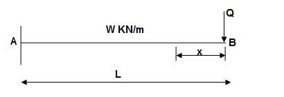
Find ΔB:

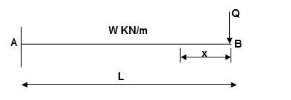
Zone Origin Limits EI M ӘM/ӘQ
BA B 0 to L EI –Q(x) – W(x2/2)-x
ΔB = ∫L0 M/EI (ӘM/ӘQ) dx = ∫L0{-W(x2/2)}(-x)dx
= W/2EI{x4/4}L0

Find
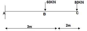
1]. Vertical Vertical deflection at ‘c’,
EI = constant
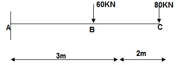
M Diagram
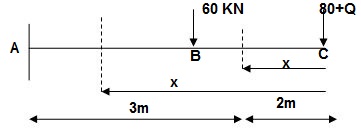
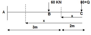
From above Fig:
Table
Zone Origin limits EI M ӘM/ӘQj
CB C 0-2 EI - (80 + Q) x - x
BA C 2-5 EI - (80 + Q) x - x-60(x-2)
ΔC = ∫20-(80) x /EI {-x} dx + ∫52{80x – 60(x-2) (-x) dx/EI}
= ∫2080x2/EI dx + ∫52 {80x2 – 60x2 + 2x} dx/EI
= 1/EI {213.33 + 4200}

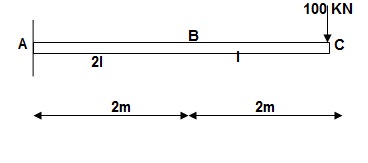
2]. Find vertical deflection at point C
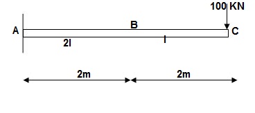
M Diagram
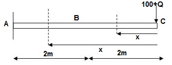
Zone Origin Limit EI M ӘM/ӘQ
CB C 0 – 2 EI - (100 + Q)x -x
BA C 2 – 4 EI -(100 + Q)x -x
ΔC = ∫20 – 100x/EI (-x)dx + ∫42 -100x/EI(-x)dx
= ∫20100x2/EIdx + ∫42100x2/2EIdx
= 266.66 + 1866.6/2 = 266.66 + 933.33
For cantilever always write load from free end. For simply write load from supports.
ΔC = 1200/EI
3]. Find slope at deflection ‘A’, deflection at ‘C’.
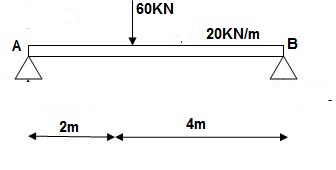
M Diagram
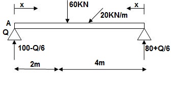
Reactions in M dia.
∑MA = VB(6) – 20 x 6 x 3 – 60(2) – Q = 0
VB = 80 + Q/6
∑Fy = VA + VB – 60 – 20 x 6 = 0
VA = 100 – Q/6
Zone Origin limits EI M ӘM/ӘQ
AC A 0 – 2 EI (100-Q/6)(x) 1 – x/6+ Q – 20(x2/2)
BC B 0 – 4 EI (80+Q/6)(x)-20x2/2 x/6
ϴA = ∫20{100(x) – 10x2}{1-x/6}dx/dEI + ∫40{80x – 10x2}x/6dx/EI
= 1/EI {135.55 + 177.78}

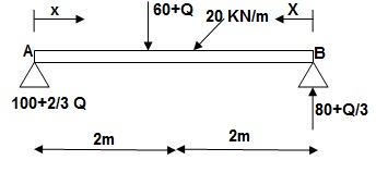
∑MA = VB (6) – 20(6)(3) – (60 + Q)2 = 0
VB = 80 + Q/3
∑Fy = VA + VB – (60 + Q) – 20(6) = 0
VA = -80 – Q/3 + 60 + Q + 120 = 0
VA = 100 + 2/3Q
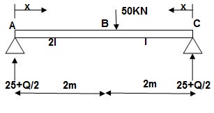
4]. Find a deflection at a point C

i) M Diagram
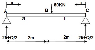
Zone Origin Limit EI MӘM/ӘQ
AC A 0 – 2 EI (25 + Q/2)x x/2
BC B 0 – 2 EI (25 + Q/2)x x/2
ΔC = ∫20(25x)x/2dx/EI + ∫2025x(x/2)dx/2EI
= 33.33 + 16.66/EI

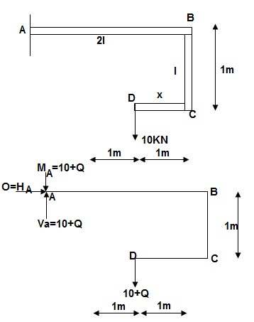
- Slope & Deflection of Beams and frames by Castiglione’s deflection 1sttheorem:
1]. Find deflection at D
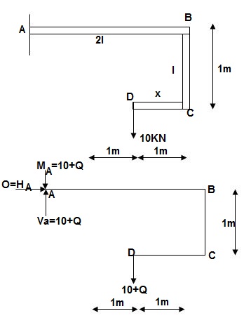
∑MA = MA – (10+Q) (1) = 0
MA = 10 + Q
∑Fy = VA – (10 + Q) = 0 VA = 10 + Q
∑Fx = HA = 0
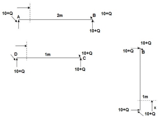
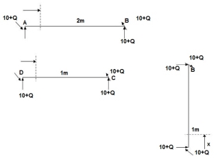
Zone origin limits EI M ӘM/ӘQ
AB A 0 – 2 2EI (10+Q)x-(10+Q) x-1
CB C 0 – 1 EI -(10 + Q) -1
DC D 0 – 1 EI -(10 + Q)x - x
ΔDy = ∫20 (10x - 10)(x-1)dx/2EI + ∫10 -10(-1)dx/EI + ∫10 -10x(-x)dx/EI
= 3.33 + 10 + 3.33/EI

2. Castiglione’s second theorem
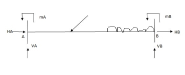
Basics (1)
i) Beam fixed at both end is called as Fixed beam
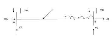
Ii) Fixed beam is statically indeterminate
Number of unknown Reactions = R=6
Number of Equilibrium equation = E=3
Dsi – R-E = 6-3 =3
Note:
For beam subjected to vertical loads lonely-horizontal reactions are zero.
For Fixed beam subjected to vertical loads only.
Number of unknown reactions = R=4
Number of equilibrium equation = E=2
Dsi – R-E = 4-2 =2

For vertically downward load fixed and moments are begging in nature.


4) Advantages of fixed beam
- Slope and deflection for fixed beam are less as compared to simply supported beam
- Net sagging moment for fixed beam is less
- Bending moment is better distributed over the length of member.
- Fixed beam bar more resistance to impact loading
5) For fixed beam,
Tangents drawn at both ends are horizontal therefore angle betn tangents is equal to area of  Diagram is equal to zero.

1= Area  ‘Dia’ =0
Position of B with respect to tangent drawn at A
BA = Area  Dia
Dia =0
=0
Key takeaways
1. ӘU/ӘQi = Δj
2. Strain energy: UAxial force = ∫L0P2dx/2EA
3. Procedure of displacement analysis by Castiglione’s theorem
Step1: Apply imaginary load ‘Q’ at section where displacement is required.
Step2: Find support reactions and draw member F.B.D’s
Step 3: Prepare table:
Zone origin limits EI M ӘM/ӘQ
Step 4: Find displacement using Δj = ∫L0M/EI {ӘM/ӘQj} dx
Betti’s theorem
Consider a linear elastic structure, subject to two different force-displacement conditions, which we may refer to as systems I and II Let (Fi) and (F) denote the sets of external forces acting on these two systems, and let (D) and (Da) denote their conjugate displacements. This is illustrated in Fig. For the case of a simple flexural member. Six coordinate points are identified, for convenience, as shown in Fig. The external forces (applied loads and support reactions), as well as deflections, in two different systems involving the same beam are shown in Figs. Respectively. The two force fields must necessarily satisfy equilibrium (considering the free-body of the beam). Similarly the two displacement fields must satisfy internal compatibility, although they may have different boundary conditions.
Applying the Principle of virtual work, by combining the force field in system I with the displacement field in system II,

Where M(x) and (x) denote the bending moment and curvature at x in system I and II respectively
As the beam is assumed to be linearly elastic,
M.(x) 
Where M(1) is the bending moment at x in system II and El is the flexural rigidity of the Substituting Eq

Diagram:
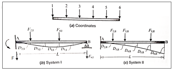
Similarly, combining the force field in system II with the displacement field in system I it can be shown that
ΣΕ, D, - MM EI
Comparing Eqs.1 and 2 and noting that the expression on the right-hand-side is identical, it follows that we arrive at the same equation, if we use a linear classic truss or frame instead of the beam in Fig. In all cases, in which there is only one type of action involved in the computation of internal work (either bending moment or axial force), there is a reciprocal nature reflected in the expression for internal virtual work. In the case of a truss, it takes the following form
Where N and N denote the axial force in the bar in systems I and II respectively, and f denotes the axial flexibility of the bar.
Betti's theorem states that the total external virtual work associated with forces (F) in system I and the conjugate displacements (D) in system II is equal to that associated with forces (F) in system II and conjugate displacements (D) in system I in a linear elastic structure.
Maxwell's Reciprocal Theorem:
It is easy to derive Maxwell's theorem from Betti's theorem, although historically, Betti started with Maxwell's theorem and extended its application. The main difference between Maxwell's and Betti's formulations lies in the fact that Maxwell dealt with the application of ne load at a time, whereas Betti considered multiple loads acting at a time.
Diagram:
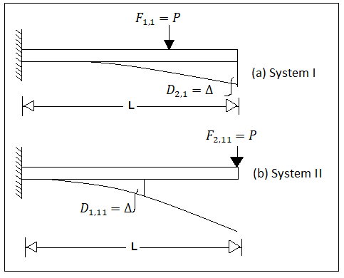
When considerations are limited to two coordinates only Consider the cantilever ss beam AB in Fig. With the same load P acting at two different locations ('1' and '2') in system I and II respectively. Let the deflection D, at the coordinate '2' due to the load P acting at '1' in system I be equal to A, as shown in Fig.
Let Din denote the deflection at the coordinate 'I' due to the load P in system shown in fig.
Applying Betti's theorem ( Eq.)
Fu Du-F D
PD PA
⇒Din = A
This establishes the reciprocal nature of P and A at two different locations.
Maxwell's reciprocal theorem states that in a linear elastic structure, if a load F acting at some coordinate location '1' causes a displacement D at some other coordinate location '2', then the same displacement D will occur at '1', if the load Facts at 2' in a separate loading condition.
It may be noted that the load F may be either a concentrated force (with N units) or a concentrated moment (with N mm units), and the displacement could be a translation (with mm units) or a rotation (in radians). It is also possible to have a reciprocal relationship between a force / displacement and moment/rotation. This can be easily understood by the concept of flexibility coefficient.
Key Takeaways:
- It is easy to derive Maxwell's theorem from Betti's theorem, although historically, Betti started with Maxwell's theorem and extended its application. The main difference between Maxwell's and Betti's formulations lies in the fact that Maxwell dealt with the application of ne load at a time, whereas Betti considered multiple loads acting at a time.
References:
1. Structural Analysis by C.S. Reddy Mc. Graw Hill
2. Structural Analysis by R.C. Hibbler Pearson Education
Unit - 3
Strain energy method
Unit - 3
Strain energy method
1. Strain Energy method
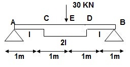
Q.1) EI = 17250 Kn.m2 find strain energy?
Solution:
∑MA = 0
30 x 2 – RB x 4 = 0
RB = 15
VA = VB = 15 KN
BMC = BMD = 15(1) = 15 KN.M
BMC = 15(2) = 30 KN.M
‘M/EI’ Dia.
C.B
A1 = 1 / 2 x 1 x 15/EI = 7.5/EI
A2 = 2 x 7.5/EI = 15/EI
A3 = 1 /2 x 2 x 7.5/EI = 7.5/EI
A4 = 1 / 2 x 15/EI x 1 = 7.5/EI
Analysis of conjugate beam:
∑MA = -RB (4) + 1/EI {7.5(2/3 x 1) + 15(2) + 7.5(2) + 7.5(3 + 1/31)} = 0
= - RB x 4 + 1/ EI [5 + 30 + 15 + 25 ] = 0
RB x 4 = 75/17250
RB = 18.75/EI
∑fy = 0
-RA + RB + A1 + A2 + A3 + A4 = 0
RA = 18.75/EI
RA = RB = ½{A1 + A2 + A3 + A4} = 18.75/EI
Slope & Deflection:
(ϴA)R.B = (SFA)C.B = (-)18.75/EI
= 18.75/EI  = 1.086 x 10⁻³rad
(ϴB)R.B = (SFB)C.B = 18.75/EI = 1.086 x 10⁻³ rad
(ΔE)R.B = (BME)CB
(BME)CB= 1/ EI { -18.75 + 7.5(1 + 1/3 x 1) + 7.5(0.5) + 3.75 (1/3 x 1)}
=1/ EI {-22.5}
ΔE = 22.5/EI  = 1.304 mm
Key takeaways
1. Find Reactions
2. M/EI Diagram
3. C.B
4. Analysis of Conjugate Beam
5. Slope and Deflection
Unit load method for statically determinate beams, frames and trusses
The unit load method helps us in finding the displacement D, at the coordinate in a structure, whose deformations are either known or can be derived. In just-rigid structures, the internal displacement field is generally known in problems of indirect loading, such as due to environmental effects and constructional errors ("lack of fit' in trusses), and it is desired to find a joint displacement that is compatible with the deformation. More commonly, we encounter problems involving direct actions, where the deformations are not given, but can be derived from the internal force response. For example, we can calculate bar elongations in truss members, if we know the axial forces in the bars. Similarly, from the bending moment distribution in flexural members, we can derive the curvatures.
Assuming linear elastic behavior (we have the following well known relationships:
(a) Between bar elongation e, and axial force N, in a truss member (having an axial rigidity EA and length L)

Where, the subscript i refer to the i bar (truss element), whose axial flexibility f, is given by

(b) Between curvature  - (having flexural rigidity(El) de and bending moment M(x) in a flexural member

Application of trusses
Consider a truss with some (real) displacement field, which may be caused by direct or indirect loading. The elongation e in all the bars are known and it is desired to find some joint displacement D, at the coordinate. If the cause is loading by direct actions, the bar forces N, can be analyzed and the corresponding bar elongations e, are easily obtainable by applying Eq. This is depicted in Fig. If the cause is due to lack of fit or temperature change, and the truss is just-rigid, the values of e, are known.
Now, consider the same truss and apply a virtual unit load, F= 1 at the coordinate as shown in Fig. Analyze the truss and arrive at all the virtual bar forces n. The force in the bar may be denoted as nij, i.e, caused by unit load applied at j.
Combining the real and virtual force fields shown in Fig. We can write the expressions for virtual work:
External work

Internal work

Applying the Principle of virtual work,


Note that D, has the same unit (dimension) as e, (usually in mm). Is dimensionally homogeneous because the bar force n (caused by a unit load) is dimensionless, having units of kN
Application to Beams and Frames
Consider a beam with some (real) displacement field, which may be caused by direct or indirect loading. The variation of curvature p(x) along the length of the beam is known and it is desired to find a deflection or a rotation DJ at the coordinate. If the cause is loading by direct actions, the bending moments M(x) can be analyzed, and the corresponding curvatures P(x) are easily obtainable by applying Eq. This is depicted in Fig. If the cause is due to indirect loading (such as due to differential shrinkage in a reinforced concrete beam), the distribution of curvatures should be known
Now, consider the same beam and apply a virtual unit load F-1 as shown in Fig... Analyze the beam and arrive at the bending moment’s m(x).
Combining the real and virtual force fields shown in Fig. We can write the expressions for virtual work:
External work

Internal work

Applying the principle of virtual work

Examples
Q. 1 considering a cantilever beam length L bent to a segment of a circle of radius R. Find the deflection at the free end.
Solution:
The curvature length as given in beam in constant with  as shown in fig
Applying the principle of virtual work


Q.2 Consider the pin jointed truss in fig. With bars numbered as indicated. Due to certain environmental change bar 1 and 2 increase in length by 1.5 mm bars 3 and 4 increases in length by 3 mm and bar 5 reduce in length by 1 mm find the horizontal movement of i th the roller support at D and the joint C
Solution:
The bar elongations gives form part of a real displacement filed with
{e} = { +1.5,+1.5.+3,+3,-1}^T mm
The required horizontal joint displacement at D and C are identified as Di and Dj resp. Using the coordinate system in shown in fig.
Applying unit load method


Where ni1 and ni2 are the force the i the bar due to F1 = 1 and F2 = 1


Therefore the horizontal movement at the roller support is given by
Case 1 Horizontal deflection D1 of the support D


Case 2 Horizontal deflection D2 of a joint C


1) Determine deflection of trust joint
1) Determine P force by given load system using joint method.
2) Remove given loud system & apply unit load to joint where the deflection desired find K force.
3) Determine PKl/ AI of each member
4) Deflection of the joint = ∑ PKl / AE
2) Analysis of indeterminate plane truss
1) Find the degree of indeterminacy
2) Select redundant member
3) Remove redundant member and find the force P in the members of the truss.
4) Remove the given loud system
a) Apply a unit load paid (either textile/ amp) in place of redundant member.
b) Find k force.
5) PKl / AE & K2L / AE
6) Correction factor = x = ∑ PKl / AE P = (P + KX) / ∑ K2L/ AE
Lock of fit of members in trust
Lock of fit is defined as little or little shorter length of any in trust.
Correction factor due to lack of
x = x (- ∑ PKl / AE) / (∑ K2L/ AE)
Where
x = shortening or excess of members
+ve = if member is short in length
-ve = if member is short in long
Find force = f = P + Kx
Formula for truss
1) Find detection -


2) Analyze indeterminate
i) F = P + KX x = (∑PKl/AE) / (∑K2l/AE)
Ii) For lock of fit =
Sign convention -ve for short member
+ve for long member
Iii) for Temp effect P = QK
Q = (xlt) / ∑ K2l/AE
Iv) for yield support
F = P + QK
DQ = DQL + FQ
DQ = Sink
DQL = ∑ PKl / AE
F = ∑ K2l / AE
2)
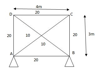
AD in short by
E = 200 Gpa
FAB = 28.04 KN FOC = 21.08
FOD = 28.04 KN FDA = 21.28
FDB = 35./20 KN FAC = 30.
1) Analyze the truss supported as shown in fig. If member AD is subjected to temp drop of 300C Taken E= 200 Gpa & coeff. Thermal expansion = 1.1 x 10⁻⁵/oc C/S area of each member in cm2 is indicated in brackets.
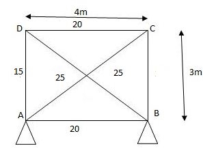
Given:
AD is subjected to Temp drop 300C.
AD is redundant member consist unit load due to drop -ve sign
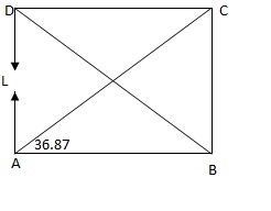
Joint A
Efy = 0
KAC5in 36.86 + 1 = 0
KAC = - 1.67 KN
Efx = 0
KAB + KAC COS 36.86 = 0
KAB = 1.34 KN
Joint D
Efy = 0
KDBsin 36.86 – 1 = 0
KDB = - 1.67 KDC = 1.33
Sr. No. | Member | Length | Area | K | …. | Q | …. |
AB |
| 4000 | 2000 | 1.33 | 3.56 |
| 11.84 |
BC |
| 3000 | 1000 | 1 | 2 |
| 8.9 |
CD |
| 4000 | 2000 | 1.33 | 3.56 | 8.9 | 11.84 |
DA |
| 3000 | 1000 | 1 | 5.56 |
| 8.90 |
DB |
| 5000 | 2000 | - 1.67 | 5.56 |
| -14.86 |
AC |
| 5000 | 2000 | - 1.67 | 2 |
| -14.86 |
P = QK

P = 8.90 x K
C/s area 10m2, rise of kmp of member BD by 300c
= 12 x 10-6 /oc E= 200Gpa.
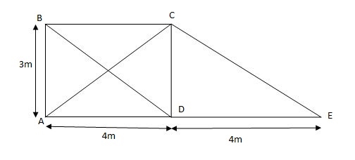
FBC = 17.77KN, FCD = 13.33 KN FAD = 12.77KN
FAC = 22.22 KN FBD = 22.22 KN FDE = FCE = 0
Effects of yielding of support in determine trusses
2) Analyze the truss supported as shown in fig., if support B sink by 3mm & c/s area of each member 400mm2.
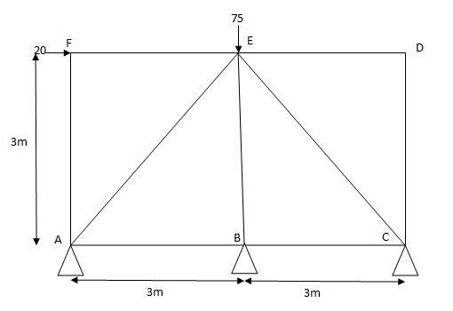
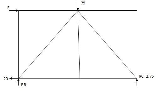
Joint A
Efx = 0
PAB + PAE COS45 – 20 = 0
PAB + PAECOS45 – 20 (1)
Efy = 0
PAESin45 – PAF + ……. = 0
PAE = 38.89 KN
PAB + - 38.89 ……… = 20
PAB = 47.49 …
Joint B
Efx = 0
- PBA + PBC = 0
PBC = 47.49 KN
PEB = 0KN
Find k force
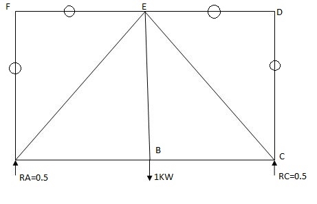
By observation
Joint A
Efx = 0
KAB + KAE COS45 = 0
KAE Sin45 + 0.5 = 0
KAE = - 0.707
KAB = - 0.49
Sr.No. | Member | Length | P | K | PK8 | P2B | F= P+ |
1. | AB | 3000 | 47.5 | -0.5 | -23.75 | + 0.25 | 76.1 |
2. | BC | 3000 | 47.5 | -0.5 | -23.75 | + 0.25 |
|
3. | CD | 3000 | 0 | 0 | 0 | 0 |
|
4. | DE | 3000 | -20 | 0 | 0 | 0 |
|
5. | EF | 3000 | -20 | 0 | 0 | 0 |
|
6. | AE | 3000 | -38.89 | -0.707 | 24.5 | 0.49 |
|
7. | EC | 3000 | -38.89 | -0.707 | 24.5 | 0.49 |
|
8. | BE | 3000 | 0 | 1 | 0 | 0 |
|
9. | AF | 4242.6 | 0 | 0 | 0 | 0 |
|
|
|
|
| E | 4500 | 1.49 X 3000 = 4440 | |
DQ = DQL + FQ
DQ1 = EPKl / AC = 0.053
F= EK2l / AE = 0.0528
DQ = 3mm
Indeterminate trusses with lack of f/f
DQ = DQF + FQ DQ = O
Q = - DQF/ K2L /AE F =K2L
DQF is +ve if the member is long
DQF is -ve if the member is short
3) Analyze the truss supported as show in fig. If the member AB is short by 5mm Take E= 200 Gpa c/s area of each member in is indicated in brackets.
AB = 5mm short consider -ve sign
E = 200 Gpa
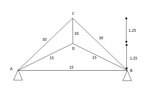
1cm = 10mm
1m = 103mm
Sr.No. | Member | Length | Area | K | K2l |
1. | AD | 2795 | 1500 | 2.23 | 9.35 |
2. | BD | 2795 | 1500 | 2.23 | 9.35 |
3. | AC | 3535 | 3000 | -1.41 | -2.34 |
4. | BC | 3535 | 3000 | -1.41 | -2.34 |
5. | CD | 1250 | 1000 | 2 | 5.00 |
6. | AB | 5000 | 1500 | 1 | 3. |
|
|
|
| EK | 31.71 |
Q = DQF/ K2l /AE = - 5000 Q = 91.54
P = QK
Joint A
Ek = 0
KADCOS 26.26 + KAC COS 45-1
KADsin26.26 + KAC sin45 = 0
KAD = 2.23
KAC = - 1.41
1. Castiglione’s1sttheorem:
It states that displacement at a point of application of load in the direction of load is equal to partial derivative of strain energy of structure with respect to load.
1]. ӘU/ӘQi = Δj
U = strain energy
Qj = Force in the direction j
Δj = Displacement in the direction j
2]. Strain energy: UAxial force = ∫L0P2dx/2EA
UB.M = ∫L0M2dx/2EI
UTorsion = ∫L0T2dx/2GJ
Deflection = translation
3]. Procedure of displacement analysis by Castiglinos theorem:
Step 1:
Apply imaginary load ‘Q’ at section where displacement is required.
Note:
1. For horizontal translation apply ‘Q’ in horizontal direction For vertical translation apply force Q in vertical direction
2. For finding ‘slope’ (rotation) apply couple Q.
Step 2: Find support reactions and draw member F.B.D’s
Step 3: Prepare table:
Zone origin limits EI M ӘM/ӘQ
Step 4: Find displacement using Δj = ∫L0M/EI{ӘM/ӘQj}dx
Find ΔB:

Zone Origin Limits EI M ӘM/ӘQ
BA B 0 to L EI –Q(x) – W(x2/2)-x
ΔB = ∫L0 M/EI (ӘM/ӘQ) dx = ∫L0{-W(x2/2)}(-x)dx
= W/2EI{x4/4}L0

Find
1]. Vertical Vertical deflection at ‘c’,
EI = constant
M Diagram
From above Fig:
Table
Zone Origin limits EI M ӘM/ӘQj
CB C 0-2 EI - (80 + Q) x - x
BA C 2-5 EI - (80 + Q) x - x-60(x-2)
ΔC = ∫20-(80) x /EI {-x} dx + ∫52{80x – 60(x-2) (-x) dx/EI}
= ∫2080x2/EI dx + ∫52 {80x2 – 60x2 + 2x} dx/EI
= 1/EI {213.33 + 4200}

2]. Find vertical deflection at point C
M Diagram
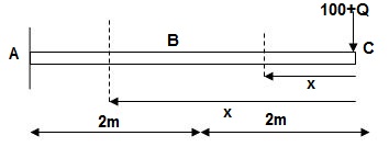
Zone Origin Limit EI M ӘM/ӘQ
CB C 0 – 2 EI - (100 + Q)x -x
BA C 2 – 4 EI -(100 + Q)x -x
ΔC = ∫20 – 100x/EI (-x)dx + ∫42 -100x/EI(-x)dx
= ∫20100x2/EIdx + ∫42100x2/2EIdx
= 266.66 + 1866.6/2 = 266.66 + 933.33
For cantilever always write load from free end. For simply write load from supports.
ΔC = 1200/EI
3]. Find slope at deflection ‘A’, deflection at ‘C’.
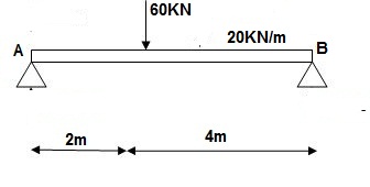
M Diagram
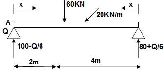
Reactions in M dia.
∑MA = VB(6) – 20 x 6 x 3 – 60(2) – Q = 0
VB = 80 + Q/6
∑Fy = VA + VB – 60 – 20 x 6 = 0
VA = 100 – Q/6
Zone Origin limits EI M ӘM/ӘQ
AC A 0 – 2 EI (100-Q/6)(x) 1 – x/6+ Q – 20(x2/2)
BC B 0 – 4 EI (80+Q/6)(x)-20x2/2 x/6
ϴA = ∫20{100(x) – 10x2}{1-x/6}dx/dEI + ∫40{80x – 10x2}x/6dx/EI
= 1/EI {135.55 + 177.78}

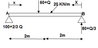
∑MA = VB (6) – 20(6)(3) – (60 + Q)2 = 0
VB = 80 + Q/3
∑Fy = VA + VB – (60 + Q) – 20(6) = 0
VA = -80 – Q/3 + 60 + Q + 120 = 0
VA = 100 + 2/3Q
4]. Find a deflection at a point C

i) M Diagram
Zone Origin Limit EI MӘM/ӘQ
AC A 0 – 2 EI (25 + Q/2)x x/2
BC B 0 – 2 EI (25 + Q/2)x x/2
ΔC = ∫20(25x)x/2dx/EI + ∫2025x(x/2)dx/2EI
= 33.33 + 16.66/EI

- Slope & Deflection of Beams and frames by Castiglione’s deflection 1sttheorem:
1]. Find deflection at D
∑MA = MA – (10+Q) (1) = 0
MA = 10 + Q
∑Fy = VA – (10 + Q) = 0 VA = 10 + Q
∑Fx = HA = 0
Zone origin limits EI M ӘM/ӘQ
AB A 0 – 2 2EI (10+Q)x-(10+Q) x-1
CB C 0 – 1 EI -(10 + Q) -1
DC D 0 – 1 EI -(10 + Q)x - x
ΔDy = ∫20 (10x - 10)(x-1)dx/2EI + ∫10 -10(-1)dx/EI + ∫10 -10x(-x)dx/EI
= 3.33 + 10 + 3.33/EI

2. Castiglione’s second theorem
Basics (1)
i) Beam fixed at both end is called as Fixed beam
Ii) Fixed beam is statically indeterminate
Number of unknown Reactions = R=6
Number of Equilibrium equation = E=3
Dsi – R-E = 6-3 =3
Note:
For beam subjected to vertical loads lonely-horizontal reactions are zero.
For Fixed beam subjected to vertical loads only.
Number of unknown reactions = R=4
Number of equilibrium equation = E=2
Dsi – R-E = 4-2 =2

For vertically downward load fixed and moments are begging in nature.


4) Advantages of fixed beam
- Slope and deflection for fixed beam are less as compared to simply supported beam
- Net sagging moment for fixed beam is less
- Bending moment is better distributed over the length of member.
- Fixed beam bar more resistance to impact loading
5) For fixed beam,
Tangents drawn at both ends are horizontal therefore angle betn tangents is equal to area of  Diagram is equal to zero.

1= Area  ‘Dia’ =0
Position of B with respect to tangent drawn at A
BA = Area  Dia
Dia =0
=0
Key takeaways
1. ӘU/ӘQi = Δj
2. Strain energy: UAxial force = ∫L0P2dx/2EA
3. Procedure of displacement analysis by Castiglione’s theorem
Step1: Apply imaginary load ‘Q’ at section where displacement is required.
Step2: Find support reactions and draw member F.B.D’s
Step 3: Prepare table:
Zone origin limits EI M ӘM/ӘQ
Step 4: Find displacement using Δj = ∫L0M/EI {ӘM/ӘQj} dx
Betti’s theorem
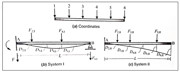
Consider a linear elastic structure, subject to two different force-displacement conditions, which we may refer to as systems I and II Let (Fi) and (F) denote the sets of external forces acting on these two systems, and let (D) and (Da) denote their conjugate displacements. This is illustrated in Fig. For the case of a simple flexural member. Six coordinate points are identified, for convenience, as shown in Fig. The external forces (applied loads and support reactions), as well as deflections, in two different systems involving the same beam are shown in Figs. Respectively. The two force fields must necessarily satisfy equilibrium (considering the free-body of the beam). Similarly the two displacement fields must satisfy internal compatibility, although they may have different boundary conditions.
Applying the Principle of virtual work, by combining the force field in system I with the displacement field in system II,

Where M(x) and (x) denote the bending moment and curvature at x in system I and II respectively
As the beam is assumed to be linearly elastic,
M.(x) 
Where M(1) is the bending moment at x in system II and El is the flexural rigidity of the Substituting Eq

Diagram:
Similarly, combining the force field in system II with the displacement field in system I it can be shown that
ΣΕ, D, - MM EI
Comparing Eqs.1 and 2 and noting that the expression on the right-hand-side is identical, it follows that we arrive at the same equation, if we use a linear classic truss or frame instead of the beam in Fig. In all cases, in which there is only one type of action involved in the computation of internal work (either bending moment or axial force), there is a reciprocal nature reflected in the expression for internal virtual work. In the case of a truss, it takes the following form
Where N and N denote the axial force in the bar in systems I and II respectively, and f denotes the axial flexibility of the bar.
Betti's theorem states that the total external virtual work associated with forces (F) in system I and the conjugate displacements (D) in system II is equal to that associated with forces (F) in system II and conjugate displacements (D) in system I in a linear elastic structure.
Maxwell's Reciprocal Theorem:
It is easy to derive Maxwell's theorem from Betti's theorem, although historically, Betti started with Maxwell's theorem and extended its application. The main difference between Maxwell's and Betti's formulations lies in the fact that Maxwell dealt with the application of ne load at a time, whereas Betti considered multiple loads acting at a time.
Diagram:
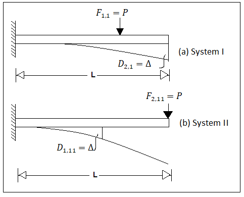
When considerations are limited to two coordinates only Consider the cantilever ss beam AB in Fig. With the same load P acting at two different locations ('1' and '2') in system I and II respectively. Let the deflection D, at the coordinate '2' due to the load P acting at '1' in system I be equal to A, as shown in Fig.
Let Din denote the deflection at the coordinate 'I' due to the load P in system shown in fig.
Applying Betti's theorem ( Eq.)
Fu Du-F D
PD PA
⇒Din = A
This establishes the reciprocal nature of P and A at two different locations.
Maxwell's reciprocal theorem states that in a linear elastic structure, if a load F acting at some coordinate location '1' causes a displacement D at some other coordinate location '2', then the same displacement D will occur at '1', if the load Facts at 2' in a separate loading condition.
It may be noted that the load F may be either a concentrated force (with N units) or a concentrated moment (with N mm units), and the displacement could be a translation (with mm units) or a rotation (in radians). It is also possible to have a reciprocal relationship between a force / displacement and moment/rotation. This can be easily understood by the concept of flexibility coefficient.
Key Takeaways:
- It is easy to derive Maxwell's theorem from Betti's theorem, although historically, Betti started with Maxwell's theorem and extended its application. The main difference between Maxwell's and Betti's formulations lies in the fact that Maxwell dealt with the application of ne load at a time, whereas Betti considered multiple loads acting at a time.
References:
1. Structural Analysis by C.S. Reddy Mc. Graw Hill
2. Structural Analysis by R.C. Hibbler Pearson Education