Unit - 4
Bucking of columns and beams
Buckling of structural detail refers back to the deformation with inside the route perpendicular to the road of motion of implemented force. Column buckling happens because of axial vertical masses (commonly compressive masses) which reasons unexpected sideways deflection of column. It is the most important purpose of failure for big columns.
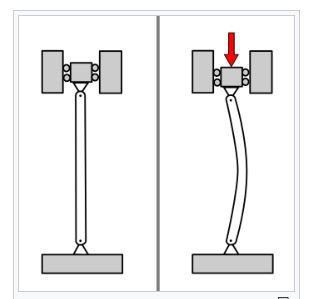
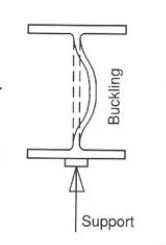
Beam buckling might also additionally arise because of each axial masses (compressive) in addition to transverse masses. Buckling because of transverse (vertical) masses happens commonly in beams of I-segment in which net of I-segment undergoes bucking. This commonly happens beneath big factor masses.
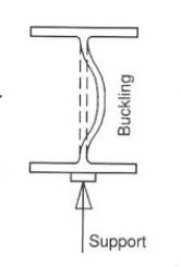
Buckling because of axial masses in beams takes area because of unexpected upward (or downward) deflection of beam beneath horizontal axial compressive forces. It commonly happens in beams having more lengths.

So the most important distinction among beam and column buckling is the route of deflection and columns buckle through vertical axial masses while beams buckle through horizontal axial masses.
Buckling of column is because of axial load and the move segment buckles on the vital point. In column buckling each net and flanges buckle however the main impact is because of axial hundreds Beam buckling is because of lateral or vertical hundreds.
This is because of beam net buckling or entire move segment buckling.
This takes region if the net isn't always enough sufficient to face up to the burden at the beam i.e., the net is slender (greater h/t) ratio or the flanges and net each aren't sufficient to take the hundreds on beam. The main impact is because of transverse loading.
I am now no longer getting into to technical is differs code to code. So the column buckles because of axial hundreds and a beam buckles because of transverse hundreds.
Column buckling is a curious and specific subject. It is possibly the most effective vicinity of structural mechanics wherein failure isn't associated with the electricity of the fabric.
A column buckling evaluation includes figuring out the most load a column can aid earlier than it collapses. But for lengthy columns, the fall apart has not anything to do with fabric yield. It is as an alternative ruled with the aid of using the column's stiffness, each fabric and geometric.
This web page will derive the usual equations of column buckling the usage of approaches. It will first cowl the standard improvement of the equations, i.e., Euler Buckling Theory.
This is the derivation located in textual content books and provided in engineering courses. But I actually have in no way favored it. Not due to the fact it's miles incorrect (its miles correct), however due to the fact I do not suppose it satisfactorily provides the bodily mechanisms governing the buckling process. That is why a 2nd derivation of the buckling equations can also be provided.
Curiously, items are called columns whilst they may be loaded axially in compression, as is the case here, however they may be called beams whilst they may be loaded transversely.
Nevertheless, beam bending concept is critical to column buckling analyses, so its miles encouraged that the reader evaluate this beam bending web page.
Key Takeaways:
This takes region if the net isn't always enough sufficient to face up to the burden at the beam i.e., the net is slender (greater h/t) ratio or the flanges and net each aren't sufficient to take the hundreds on beam
It is as an alternative ruled with the aid of using the column's stiffness, each fabric and geometric.
Euler Buckling Theory is the classical theory presented in textbooks and classrooms. It begins simply by noting that the internal bending moment in a loaded and deformed column is −Py where P is the compressive load and y is the column deflection. So insert −Py in for MM in the beam bending equation, EIy′′=M
EIy′′=M
EIy″=M=−Py
This produces the following differential equation
EIy′′+Py=0 which has the solution
y=Asin(√P/EIx)+Bcos (√P/EIx)
Where AA and BB are constants determined from the boundary conditions.
The boundary conditions are y=0 at x=0 and x=L
The first boundary condition, y=0 at x=0, leads to the conclusion that B=0B=0. And this leaves
y = Asin(√P/EIx)
So far, so good. But it's at this point that the classical derivation tends to leave physical intuition behind and become overtly mathematical...
Things become very interesting with the 2nd boundary condition because, as we will see, it does not lead to determination of the unknown constant, AA. To see this, insert the second boundary condition as follows.
y(L)=0=Asin ((√P/EI).L)
There are basically two possibilities here. In the first case, A=0, but this is boring because it leads to the result that all displacements are zero. This is just the non-buckled solution. Before the column buckles, its lateral displacements are simply zero.
The second case is the interesting one, and the one directly related to column buckling. The second method of satisfying the boundary condition is to note that sin(π)=0. Therefore the way to satisfy the boundary condition is to require that the argument in the equation, ((√P/EI).L) must equal ππ. Doing so gives
√(P/EI)L= π
And solving for P gives
Pcr = π2EI/L2
This is the classical Euler buckling theory result. It gives the critical value of load PP, called Pcr, above which, the column will buckle.
This result is perfectly legit. However, as should be evident by now, it is very mathematical in nature, and provides little physical insight as a result. The up-coming derivation below will present an alternative method of arriving at the same equation that I believe provides a much more direct physical connection to the buckling process than the above derivation did.
Rankines Theory:
Empirical or semi-empirical strategies are usually used to expect the failure of column of any length: those then shape the idea for secure load or secure strain tables given in Codes of Practice. One such approach which offers appropriate settlement with test is that due to Rankine.
Suppose that P is the failure load of a column of a given fabric and of any length. Suppose additionally that P S is the failure load in compression of a quick column of the same material and that P CR is the buckling load of a protracted slim column, once more of the same material. The Rankine principle proposes that

Equation is valid for a very short column since 1/PCR = 0 and
P then PS
The equation is also valid for a long slender column since 1/ P S is small compared with 1/P CR;
Thus P - PCR. Therefore, Eq. Is seen to hold for extremes in column length. Now let
S be the yield stress in compression of the material of the column and A
Its cross-sectional area. Then
Also from Eq. PS = σSA

Substituting for PS and PCR in Eq. (21.26) we have

Thus 
So that 
Dividing top and bottom of the right hand side of this equation by 

But I = Ar2 so that

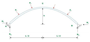
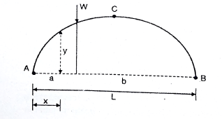
An ordinary -hinged arch is proven in Fig... In the case of -hinged arch, we've 4 unknown reactions, but there are best 3 equations of equilibrium available. Hence, the diploma of statically indeterminacy is one for two hinged arch.
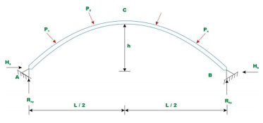
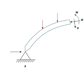
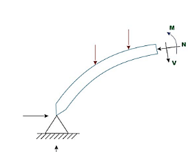
The fourth equation is written thinking about deformation of the arch. The unknown redundant response is calculated with the aid of using noting that the horizontal displacement of hinge Hb B is zero. In well known the horizontal response with inside the hinged arch is evaluated with the aid of using trustworthy utility of the concept of least work, which states that the partial spinoff of the pressure strength of a statically indeterminate shape with appreciate to statically indeterminate motion ought to Hence to obtain, horizontal response, one need to increase an expression for pressure strength. Typically, any phase of the arch is subjected to shear force V, bending moment M and the axial compression. The pressure strength because of bending is calculated from the subsequent expression.

The above expression is just like the only used with inside the case of hetero beams. However, on this case, the mixing wishes to be evaluated alongside the curved arch period. In the above equation, s is the period of the centerline of the arch, I is the instant of inertia of the arch pass phase, and E is the Young’s modulus of the arch material. The pressure strength because of shear is small in comparison to the pressure strength because of bending and is typically left out with inside the analysis. In the case of flat arches, the pressure strength because of axial compression may be considerable and is given with the aid of using,

The total strain energy of the arch is given by,

Now, according to the principle of least work

Where H is chosen as the redundant reaction.

Solving equation the horizontal reaction H is evaluated.
In Fig. There are hinges A and B, and there are 4 help reactions. There are handiest 3 numbers of equations of equilibrium, so hinged arches are indeterminate to the diploma identical to 1.
If we should discover all of the 4 unknown reactions of the 2 hinged arch, then, we want one extra equilibrium equation. So the indeterminacy of a hinged arch is identical to 1.
We can without difficulty discover the Va and Vb, through taking algebraic sum of all of the moments approximately A or B identical to 0.
To discover the horizontal reactions Ha and Hb, many books suggest to apply the Castiglione’s first theorem.
The relative displacement of the both hinge with appreciate to different is zero, so the partial by-product of the pressure strength of the beam with appreciate to the horizontal response might be zero.
So first we should discover the equation of the pressure strength of the complete beam, after which partly differentiate it w.r.t. To the horizontal reactions, after which equate it to zero. It will become the fourth equation, and we will get the cost of the horizontal response.
Now as all of the help reactions are found, we will without difficulty plot the bending second diagram, for the arch.
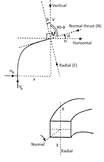
Now at any move of the arch the vertical and the horizontal forces may be resolved alongside directions, one is tangent to the move sectional floor of the arch and every other is ordinary to the move sectional floor of the arch. It offers upward push to every other terms:
- Radial Shear
- Normal thrust.
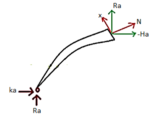
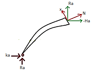
Due to the curved form of the arch, in contrast to shear pressure and axial thrust in a straight beam, the course of the everyday thrust and the radial shear alternate continuously from one give up of the arch to the other.
To discover the importance of the radial shear and the everyday thrust, first we must discover the course of those.
To discover the course, we honestly discover the slope of the arch (perspective w.r.t. Horizontal), at that segment which, may be located via way of means of writing the equation of the circle or the parabola in phrases of y and x co-ordinates, relying upon the form of the arch and then differentiating the y w.r.t. x offers us the slope of the equation.
Putting the corresponding price of the x on the given pass segment, offers us the slope on the given pass segment. After locating the perspective, it will become smooth to clear up the forces into directions, of the radial shear and the everyday thrust.
In the discern proven below, you need to clear up the forces on the segment alongside the R and N, to discover the Radial Shear and the Normal Thrust.
Key Takeaways:
- If we should discover all of the 4 unknown reactions of the 2 hinged arch, then, we want one extra equilibrium equation. So the indeterminacy of a hinged arch is identical to 1.
- It will become the fourth equation, and we will get the cost of the horizontal response.
A three hinged arch is a statically determinate structure, having a hinge at each abutment or springing and also at the crown.
There are in all four reaction components (two at each hinge i.e. H and V). Three equations are available from the static equilibrium and one additional equation is available from the fact that the B.M. At the hinge at the crown is zero. Thus, the value of H can easily be calculated for any given load system.
Components of arch is shown in Fig.
A section of arch is subjected to three straining action under the action of loads, these are
(i) Bending moment (M).
(ii) Normal thrust (N).
(iii) Radial shear (F).
The B.M. Is calculated using Eddy's theorem which is stated as, "The B.M. At any section of an arch is equal to the vertical intercept between the linear arch and the centerline of the actual arch."
B.M. At any section= Sum of moment due to loads Vertical reactions
(R), and Horizontal Thrust (H).
= Beam moment + H. Moment
Diagram:
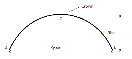
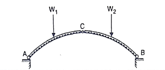
A three hinged arch consists of Two parts AC and BC hinged at C and supports A and B are two external hinges (Like an abutment).
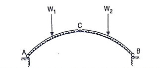
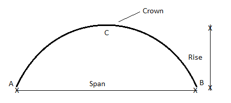
1. Span of an arch: The horizontal distance between Two lower hinge supports A and B is known as span of arch
2. Rise of the arch: When supports A and B are at the same levels, the height of crown (C) is called rise of the arch. If the shape of the arch is parabolic then it is called parabolic
Diagram:
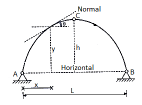
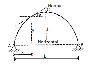
Equation type: 


C=
Equation of parabola is:
Y=
1. Bending moment diagram for three hinged arch:
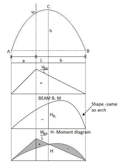
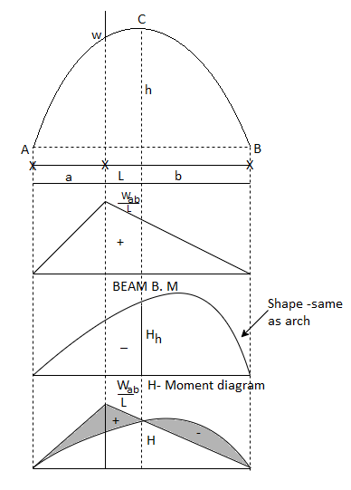
We know that for an arch, bending moment at any point is equal to beam BM-Hy (Refer comparison between arch and beam). Hy is called H-Moment. It varies with respect to Y. Therefore the shape of BM due to Hy should be the shape of the arch. Therefore to draw the BMD for an arch, draw the BMD for the beam over that superimpose the H-moment
Diagram as shown in Fig.
2. Steps of analysis of three hinged arch:
Step 1) Find reaction components
Draw F.B.D of arch taking two reaction components at each support and apply
Step 2) Find normal thrust and radial shear at any section.
Step 3) Find B.M. At any section
UseMx= Beam moment - H moment
Key takeaway:
Step 1) Find reaction components
Step 2) Find normal thrust and radial shear at any section
Step 3) Find B.M at any section
Suspension cable with three hinged stiffening girders subjected to dead and live loads
Cables are structural elements that resist loads by developing axial tension. They may form the primary load resisting structural component, as in the case of suspension bridges, cable stayed bridges, suspended roof systems, cable car systems, etc. In such cases, the main loads on the cables are usually gravity loads (either concentrated or distributed) transmitted from the suspended system (deck slab, roof or trolley). Compared to these heavy loads, the self-weight of the cable is usually negligible, and hence is generally ignored in the force analysis. In other applications, the cables may form a secondary support system, as in guyed towers, transmission line towers and derricks. In these cases, the cables do not support loads along their length, except for their self-weight and wind/snow loads acting on them.
The main cables (thick wire ropes) pass over the top of the pylons and are anchored to strong supports in the ground. The connection between the cable and the pylon may be either in the form of pulley support or saddle support.
In the case of the pulley support, the tension in the cable on either side is more or-less equal In order to satisfy force equilibrium, the resultant force in the cable support system, having both vertical and horizontal components, gets transmitted to the supporting pylon, using either a pulley arrangement or a saddle support.
In the pulley arrangement, the horizontal component of the main cable tension acting at the top of the pylon can result in a large bending moment at the base of the pylon, which acts like a vertical cantilever, and needs to be suitably designed for this purpose. This bending action on account of differences in the horizontal component of cable tension on either side of the pylon, gets practically eliminated in the saddle (roller) support arrangement which is shown in fig.
This requires the tension in the anchored portion of the cable not to be equal to the cable tension on the other side, the value being determined by horizontal force equilibrium.
With such a profile, the stiffening girder transmits practically no dead load to the al supports, as the load (including the self-weight of the stiffening girders) is carried by the spenders to the overhead cables.
However, under the action of moving live loads, the transmission of internal forces gets complicated. In order to ensure that the overall cable profile does not change with every passing vehicular load, and that it consistently remain parabolic, it is important to achieve a high degree of vertical stiffness in the so-called stiffening girders. The high stiffness in these girders helps to retain their straight profile, and thus also the parabolic cable profile, thereby ensuring that the forces in the suspenders are more-or-less equal, even under the action of concentrated live loads that may be eccentrically located.
Shear Force, normal thrust and radial shear for three hinged arches
Diagram:
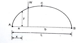
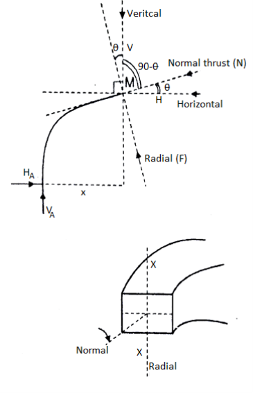
At any section X-X of arch the total force acting along the normal is called normal thrust and total force acting along the radial direction is called radial shear. For the case shown in fig.
To determine normal thrust and radial shear at any point cut the arch into 2 parts. Consider any 1 part. Determine net horizontal (H) and vertical (V) force on to the section. Using these forces calculate normal thrust and radial shear.
Components of two forces V and H along normal direction.
We get,
Normal thrust N =+H
N =H
Treat the normal thrust as + ve if it is acting towards the arch and - ve if it is away from the arch.
Composition of two forces V and H along radial direction
We get,
Radial shear F = +V 
F = V 
Treat force up the radial direction+ ve and down the radial direction as - ve.
Key Takeaways:
- This bending action on account of differences in the horizontal component of cable tension on either side of the pylon, gets practically eliminated in the saddle (roller) support arrangement which is shown in fig.
- The high stiffness in these girders helps to retain their straight profile, and thus also the parabolic cable profile, thereby ensuring that the forces in the suspenders are more-or-less equal, even under the action of concentrated live loads that may be eccentrically located
References:
1. Structural Analysis by C.S. Reddy Mc. Graw Hill
2. Structural Analysis by R.C. Hibbler Pearson Education
Unit - 4
Bucking of columns and beams
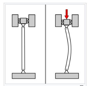
Buckling of structural detail refers back to the deformation with inside the route perpendicular to the road of motion of implemented force. Column buckling happens because of axial vertical masses (commonly compressive masses) which reasons unexpected sideways deflection of column. It is the most important purpose of failure for big columns.
Beam buckling might also additionally arise because of each axial masses (compressive) in addition to transverse masses. Buckling because of transverse (vertical) masses happens commonly in beams of I-segment in which net of I-segment undergoes bucking. This commonly happens beneath big factor masses.
Buckling because of axial masses in beams takes area because of unexpected upward (or downward) deflection of beam beneath horizontal axial compressive forces. It commonly happens in beams having more lengths.

So the most important distinction among beam and column buckling is the route of deflection and columns buckle through vertical axial masses while beams buckle through horizontal axial masses.
Buckling of column is because of axial load and the move segment buckles on the vital point. In column buckling each net and flanges buckle however the main impact is because of axial hundreds Beam buckling is because of lateral or vertical hundreds.
This is because of beam net buckling or entire move segment buckling.
This takes region if the net isn't always enough sufficient to face up to the burden at the beam i.e., the net is slender (greater h/t) ratio or the flanges and net each aren't sufficient to take the hundreds on beam. The main impact is because of transverse loading.
I am now no longer getting into to technical is differs code to code. So the column buckles because of axial hundreds and a beam buckles because of transverse hundreds.
Column buckling is a curious and specific subject. It is possibly the most effective vicinity of structural mechanics wherein failure isn't associated with the electricity of the fabric.
A column buckling evaluation includes figuring out the most load a column can aid earlier than it collapses. But for lengthy columns, the fall apart has not anything to do with fabric yield. It is as an alternative ruled with the aid of using the column's stiffness, each fabric and geometric.
This web page will derive the usual equations of column buckling the usage of approaches. It will first cowl the standard improvement of the equations, i.e., Euler Buckling Theory.
This is the derivation located in textual content books and provided in engineering courses. But I actually have in no way favored it. Not due to the fact it's miles incorrect (its miles correct), however due to the fact I do not suppose it satisfactorily provides the bodily mechanisms governing the buckling process. That is why a 2nd derivation of the buckling equations can also be provided.
Curiously, items are called columns whilst they may be loaded axially in compression, as is the case here, however they may be called beams whilst they may be loaded transversely.
Nevertheless, beam bending concept is critical to column buckling analyses, so its miles encouraged that the reader evaluate this beam bending web page.
Key Takeaways:
This takes region if the net isn't always enough sufficient to face up to the burden at the beam i.e., the net is slender (greater h/t) ratio or the flanges and net each aren't sufficient to take the hundreds on beam
It is as an alternative ruled with the aid of using the column's stiffness, each fabric and geometric.
Euler Buckling Theory is the classical theory presented in textbooks and classrooms. It begins simply by noting that the internal bending moment in a loaded and deformed column is −Py where P is the compressive load and y is the column deflection. So insert −Py in for MM in the beam bending equation, EIy′′=M
EIy′′=M
EIy″=M=−Py
This produces the following differential equation
EIy′′+Py=0 which has the solution
y=Asin(√P/EIx)+Bcos (√P/EIx)
Where AA and BB are constants determined from the boundary conditions.
The boundary conditions are y=0 at x=0 and x=L
The first boundary condition, y=0 at x=0, leads to the conclusion that B=0B=0. And this leaves
y = Asin(√P/EIx)
So far, so good. But it's at this point that the classical derivation tends to leave physical intuition behind and become overtly mathematical...
Things become very interesting with the 2nd boundary condition because, as we will see, it does not lead to determination of the unknown constant, AA. To see this, insert the second boundary condition as follows.
y(L)=0=Asin ((√P/EI).L)
There are basically two possibilities here. In the first case, A=0, but this is boring because it leads to the result that all displacements are zero. This is just the non-buckled solution. Before the column buckles, its lateral displacements are simply zero.
The second case is the interesting one, and the one directly related to column buckling. The second method of satisfying the boundary condition is to note that sin(π)=0. Therefore the way to satisfy the boundary condition is to require that the argument in the equation, ((√P/EI).L) must equal ππ. Doing so gives
√(P/EI)L= π
And solving for P gives
Pcr = π2EI/L2
This is the classical Euler buckling theory result. It gives the critical value of load PP, called Pcr, above which, the column will buckle.
This result is perfectly legit. However, as should be evident by now, it is very mathematical in nature, and provides little physical insight as a result. The up-coming derivation below will present an alternative method of arriving at the same equation that I believe provides a much more direct physical connection to the buckling process than the above derivation did.
Rankines Theory:
Empirical or semi-empirical strategies are usually used to expect the failure of column of any length: those then shape the idea for secure load or secure strain tables given in Codes of Practice. One such approach which offers appropriate settlement with test is that due to Rankine.
Suppose that P is the failure load of a column of a given fabric and of any length. Suppose additionally that P S is the failure load in compression of a quick column of the same material and that P CR is the buckling load of a protracted slim column, once more of the same material. The Rankine principle proposes that

Equation is valid for a very short column since 1/PCR = 0 and
P then PS
The equation is also valid for a long slender column since 1/ P S is small compared with 1/P CR;
Thus P - PCR. Therefore, Eq. Is seen to hold for extremes in column length. Now let
S be the yield stress in compression of the material of the column and A
Its cross-sectional area. Then
Also from Eq. PS = σSA

Substituting for PS and PCR in Eq. (21.26) we have

Thus 
So that 
Dividing top and bottom of the right hand side of this equation by 

But I = Ar2 so that

An ordinary -hinged arch is proven in Fig... In the case of -hinged arch, we've 4 unknown reactions, but there are best 3 equations of equilibrium available. Hence, the diploma of statically indeterminacy is one for two hinged arch.
The fourth equation is written thinking about deformation of the arch. The unknown redundant response is calculated with the aid of using noting that the horizontal displacement of hinge Hb B is zero. In well known the horizontal response with inside the hinged arch is evaluated with the aid of using trustworthy utility of the concept of least work, which states that the partial spinoff of the pressure strength of a statically indeterminate shape with appreciate to statically indeterminate motion ought to Hence to obtain, horizontal response, one need to increase an expression for pressure strength. Typically, any phase of the arch is subjected to shear force V, bending moment M and the axial compression. The pressure strength because of bending is calculated from the subsequent expression.

The above expression is just like the only used with inside the case of hetero beams. However, on this case, the mixing wishes to be evaluated alongside the curved arch period. In the above equation, s is the period of the centerline of the arch, I is the instant of inertia of the arch pass phase, and E is the Young’s modulus of the arch material. The pressure strength because of shear is small in comparison to the pressure strength because of bending and is typically left out with inside the analysis. In the case of flat arches, the pressure strength because of axial compression may be considerable and is given with the aid of using,

The total strain energy of the arch is given by,

Now, according to the principle of least work

Where H is chosen as the redundant reaction.

Solving equation the horizontal reaction H is evaluated.
In Fig. There are hinges A and B, and there are 4 help reactions. There are handiest 3 numbers of equations of equilibrium, so hinged arches are indeterminate to the diploma identical to 1.
If we should discover all of the 4 unknown reactions of the 2 hinged arch, then, we want one extra equilibrium equation. So the indeterminacy of a hinged arch is identical to 1.
We can without difficulty discover the Va and Vb, through taking algebraic sum of all of the moments approximately A or B identical to 0.
To discover the horizontal reactions Ha and Hb, many books suggest to apply the Castiglione’s first theorem.
The relative displacement of the both hinge with appreciate to different is zero, so the partial by-product of the pressure strength of the beam with appreciate to the horizontal response might be zero.
So first we should discover the equation of the pressure strength of the complete beam, after which partly differentiate it w.r.t. To the horizontal reactions, after which equate it to zero. It will become the fourth equation, and we will get the cost of the horizontal response.
Now as all of the help reactions are found, we will without difficulty plot the bending second diagram, for the arch.
Now at any move of the arch the vertical and the horizontal forces may be resolved alongside directions, one is tangent to the move sectional floor of the arch and every other is ordinary to the move sectional floor of the arch. It offers upward push to every other terms:
- Radial Shear
- Normal thrust.
Due to the curved form of the arch, in contrast to shear pressure and axial thrust in a straight beam, the course of the everyday thrust and the radial shear alternate continuously from one give up of the arch to the other.
To discover the importance of the radial shear and the everyday thrust, first we must discover the course of those.
To discover the course, we honestly discover the slope of the arch (perspective w.r.t. Horizontal), at that segment which, may be located via way of means of writing the equation of the circle or the parabola in phrases of y and x co-ordinates, relying upon the form of the arch and then differentiating the y w.r.t. x offers us the slope of the equation.
Putting the corresponding price of the x on the given pass segment, offers us the slope on the given pass segment. After locating the perspective, it will become smooth to clear up the forces into directions, of the radial shear and the everyday thrust.
In the discern proven below, you need to clear up the forces on the segment alongside the R and N, to discover the Radial Shear and the Normal Thrust.
Key Takeaways:
- If we should discover all of the 4 unknown reactions of the 2 hinged arch, then, we want one extra equilibrium equation. So the indeterminacy of a hinged arch is identical to 1.
- It will become the fourth equation, and we will get the cost of the horizontal response.
A three hinged arch is a statically determinate structure, having a hinge at each abutment or springing and also at the crown.
There are in all four reaction components (two at each hinge i.e. H and V). Three equations are available from the static equilibrium and one additional equation is available from the fact that the B.M. At the hinge at the crown is zero. Thus, the value of H can easily be calculated for any given load system.
Components of arch is shown in Fig.
A section of arch is subjected to three straining action under the action of loads, these are
(i) Bending moment (M).
(ii) Normal thrust (N).
(iii) Radial shear (F).
The B.M. Is calculated using Eddy's theorem which is stated as, "The B.M. At any section of an arch is equal to the vertical intercept between the linear arch and the centerline of the actual arch."
B.M. At any section= Sum of moment due to loads Vertical reactions
(R), and Horizontal Thrust (H).
= Beam moment + H. Moment
Diagram:
A three hinged arch consists of Two parts AC and BC hinged at C and supports A and B are two external hinges (Like an abutment).
1. Span of an arch: The horizontal distance between Two lower hinge supports A and B is known as span of arch
2. Rise of the arch: When supports A and B are at the same levels, the height of crown (C) is called rise of the arch. If the shape of the arch is parabolic then it is called parabolic
Diagram:
Equation type: 


C=
Equation of parabola is:
Y=
1. Bending moment diagram for three hinged arch:
We know that for an arch, bending moment at any point is equal to beam BM-Hy (Refer comparison between arch and beam). Hy is called H-Moment. It varies with respect to Y. Therefore the shape of BM due to Hy should be the shape of the arch. Therefore to draw the BMD for an arch, draw the BMD for the beam over that superimpose the H-moment
Diagram as shown in Fig.
2. Steps of analysis of three hinged arch:
Step 1) Find reaction components
Draw F.B.D of arch taking two reaction components at each support and apply
Step 2) Find normal thrust and radial shear at any section.
Step 3) Find B.M. At any section
UseMx= Beam moment - H moment
Key takeaway:
Step 1) Find reaction components
Step 2) Find normal thrust and radial shear at any section
Step 3) Find B.M at any section
Suspension cable with three hinged stiffening girders subjected to dead and live loads
Cables are structural elements that resist loads by developing axial tension. They may form the primary load resisting structural component, as in the case of suspension bridges, cable stayed bridges, suspended roof systems, cable car systems, etc. In such cases, the main loads on the cables are usually gravity loads (either concentrated or distributed) transmitted from the suspended system (deck slab, roof or trolley). Compared to these heavy loads, the self-weight of the cable is usually negligible, and hence is generally ignored in the force analysis. In other applications, the cables may form a secondary support system, as in guyed towers, transmission line towers and derricks. In these cases, the cables do not support loads along their length, except for their self-weight and wind/snow loads acting on them.
The main cables (thick wire ropes) pass over the top of the pylons and are anchored to strong supports in the ground. The connection between the cable and the pylon may be either in the form of pulley support or saddle support.
In the case of the pulley support, the tension in the cable on either side is more or-less equal In order to satisfy force equilibrium, the resultant force in the cable support system, having both vertical and horizontal components, gets transmitted to the supporting pylon, using either a pulley arrangement or a saddle support.
In the pulley arrangement, the horizontal component of the main cable tension acting at the top of the pylon can result in a large bending moment at the base of the pylon, which acts like a vertical cantilever, and needs to be suitably designed for this purpose. This bending action on account of differences in the horizontal component of cable tension on either side of the pylon, gets practically eliminated in the saddle (roller) support arrangement which is shown in fig.
This requires the tension in the anchored portion of the cable not to be equal to the cable tension on the other side, the value being determined by horizontal force equilibrium.
With such a profile, the stiffening girder transmits practically no dead load to the al supports, as the load (including the self-weight of the stiffening girders) is carried by the spenders to the overhead cables.
However, under the action of moving live loads, the transmission of internal forces gets complicated. In order to ensure that the overall cable profile does not change with every passing vehicular load, and that it consistently remain parabolic, it is important to achieve a high degree of vertical stiffness in the so-called stiffening girders. The high stiffness in these girders helps to retain their straight profile, and thus also the parabolic cable profile, thereby ensuring that the forces in the suspenders are more-or-less equal, even under the action of concentrated live loads that may be eccentrically located.
Shear Force, normal thrust and radial shear for three hinged arches
Diagram:
At any section X-X of arch the total force acting along the normal is called normal thrust and total force acting along the radial direction is called radial shear. For the case shown in fig.
To determine normal thrust and radial shear at any point cut the arch into 2 parts. Consider any 1 part. Determine net horizontal (H) and vertical (V) force on to the section. Using these forces calculate normal thrust and radial shear.
Components of two forces V and H along normal direction.
We get,
Normal thrust N =+H
N =H
Treat the normal thrust as + ve if it is acting towards the arch and - ve if it is away from the arch.
Composition of two forces V and H along radial direction
We get,
Radial shear F = +V 
F = V 
Treat force up the radial direction+ ve and down the radial direction as - ve.
Key Takeaways:
- This bending action on account of differences in the horizontal component of cable tension on either side of the pylon, gets practically eliminated in the saddle (roller) support arrangement which is shown in fig.
- The high stiffness in these girders helps to retain their straight profile, and thus also the parabolic cable profile, thereby ensuring that the forces in the suspenders are more-or-less equal, even under the action of concentrated live loads that may be eccentrically located
References:
1. Structural Analysis by C.S. Reddy Mc. Graw Hill
2. Structural Analysis by R.C. Hibbler Pearson Education