Unit - 5
Slope defection method as applied to indeterminate beams
1. Slope Deflection Method
- Slope=

- Deflection=

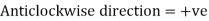
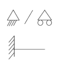
- Sign Convention

- Simply supported Beam
At support  form
form 
At the simply supported end
 is always zero.
 is always zero.
2. Cantilever beam

1.  =0 at the fixed end at force end

 At Fixed end
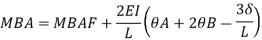
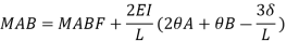
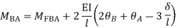
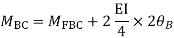
2. Slope deflection equation:
When a member of a structure is loaded, it deforms from its original position and internal forces are developed. The end moments can be expressed in terms of
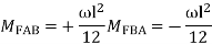
(i) Fixed end moments (FEM) of the member due to transverse loading on the member
(ii) The slopes or rotations at the end
(iii) The end deflections or joint translations. These expressions are called as Slope-Deflection equations.
There are two slope deflection equations for each member.
These slope deflection equations are derived from superposition of the end moments caused by various actions and displacement.


Similarly
Where,
 = be the slope or rotation at joint A
 = be the slope or rotation at joint B.
 = be the end deflection or translation of joint A.
 = be the end deflection or translation of joint B.
 B/A = Relative translation of joint B with respect to joint A
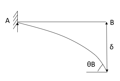
 AB Angle between the unreformed member and the line joining the deflected joints.
Here  >
> Therefore
  B/A is positive
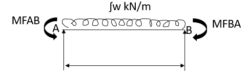
MAB = Moment at A of member AB
МВА = Moment at B of member BA
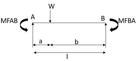
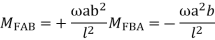
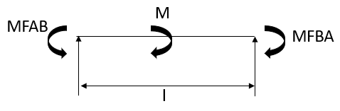
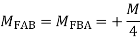
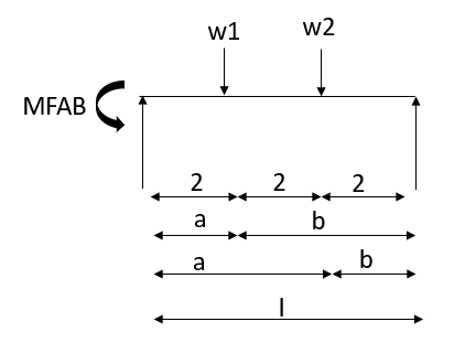
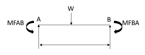
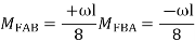
3. Fixed End Moments: Standard Cases Fixed End Moments
Standard Cases
1.


2.

3.
4.
5.
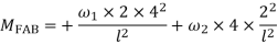
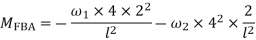
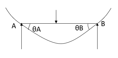
4. Derivation of slope Deflection Method
- In beam, a continuous beam ABCD, consider AB part and take fixed end moments and rotation at support as given below
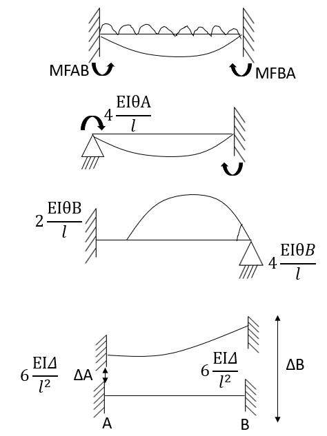
As per the diagram
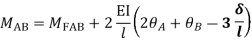
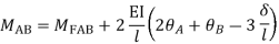
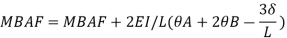
Slop deflection equations are
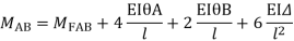
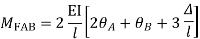
.
5. Types of numerical for slope deflection method
1. The beam is without sink (is zero.)
2. Beam with sink (is given)
3. Analyze of the frame without sink
4. Analyze the frame with the sink.
6. Steps for analysis of the slope deflection method
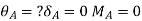
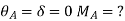
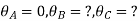
1. Find unknown slope .
.
2. Find fixed end moment
3. Apply the slope deflection equation.


4. Use the joint equilibrium equation at the joint.
5. Find final moments.
6. Find relation by equation &Draw SFI
7. Draw BMD

Hod


Step-III Apply equilibrium condition at joint


Step-IV Find final moments.


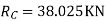
Step-V Find reaction
S.F. At A Take a moment at A is


SFD & BMD

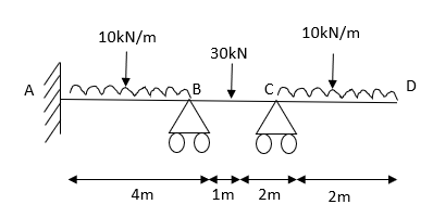
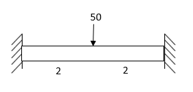
- Determine support moments & draw BMD for the beam shown by using S.D.
Step-I) Find Dki

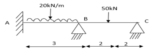
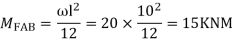
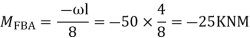
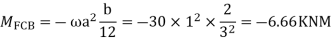
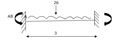
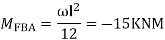
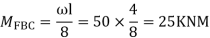
Step II) Find fixed end moments


For BC Beam


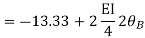
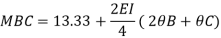
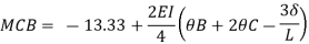
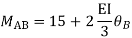
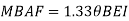
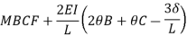
Step-III) Apply the SD equation
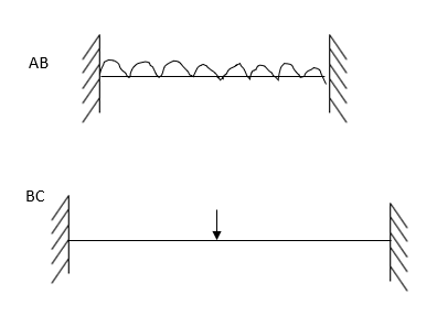
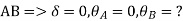
AB=>


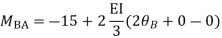

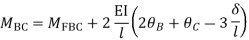
BC=>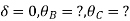


Step- IV) Apply equilibrium condition joint B


 ------- due to Hinge support


Put in equation (1) (2) (3) & (4)


Draw BMD Diagram

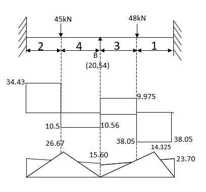
2. Analyze the continuous beam ABCD by S.D. Method draw BMD
Modify Diagram

Step- I) Fixed end moment


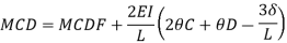
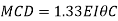
Apply S.D. Equation


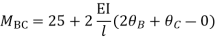
Member BC

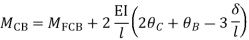
Member CD


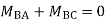
Step 4) To apply condition of equilibrium
At joint B
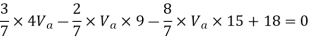
Adding equation 1and 2


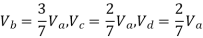
Due to symmetry


Step 5) To find end moments at joint


Step 6) Draw BMD and SFD
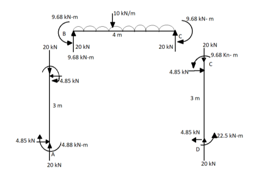

SFD

BMD

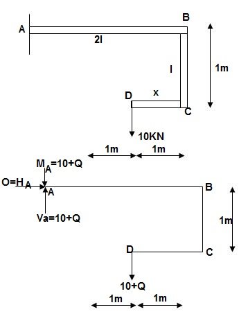
∑MA = MA – (10+Q)(1) = 0
MA = 10 + Q
∑F y = VA – (10 + Q) = 0 VA = 10 + Q
∑F x = HA = 0
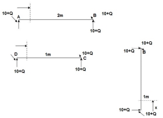
Zone origin limits EI M ӘM/ӘQ
AB A 0 – 2 2EI (10+Q) x-(10+Q) x-1
CB C 0 – 1 EI - (10 + Q) -1
DC D 0 – 1 EI - (10 + Q) x - x
Δ D y = ∫20 (10x - 10)(x-1)dx/2EI + ∫10 -10(-1)dx/EI + ∫10 -10x(-x)dx/EI
= 3.33 + 10 + 3.33/EI
 Δ D y = 16.66/EI ( )
1. Portal method
This method is applicable for low rise structures. In low rise structures shear deformations are dominant, therefore this method simplifying assumptions regarding horizontal shear in column. Each bay of a structure as a portal frame and horizontal force is distributed equally among them. This means each interior column takes twice as much as the exterior column
Assumptions:
- The points of inflection or point of contra flexure are located at the mid height of each column. However for hinged column base it assumed at hinged column base
- The point of inflection are located at mid span of beam
- The horizontal shear at any floor is divided among all the basis that each interior column take twice as much as the exterior column
Steps
1) Assume first assumption -> mark point of contra flexure at centre of each column & beam
2) Apply 2nd assumption -> Horizontal shear is double at interior column.
3) Find P& Q force.
4) Find moment at beam = always same as moment of column.
5) Find shear force at beam=moment at 
Problems:
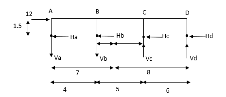
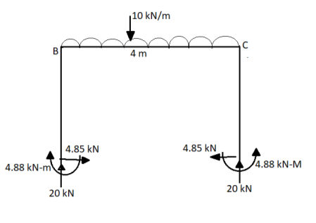
1) Analyse the given figure by portal method
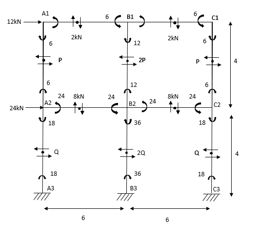
Step 1) 1st Assumption-> Mark point of contraflexure of each member
Step 2) 2nd Assumption -> Interior Horizontal shear is double than (extreme) lost member.
P+2P+P=12
P=3KN
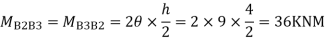
Q+2Q+Q=12+24
Q=9KN
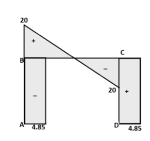
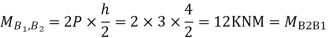
Step 3) Moment at the end of column
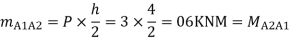

Step 4) Moment at column


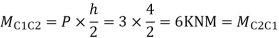
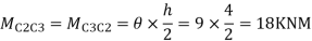
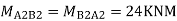
Step5) Moment at the end of roof Beam

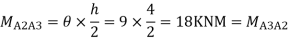
Step 6) Moment at the end of floor Beam


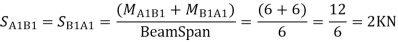
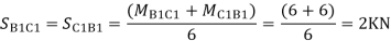
Step 7) Shear force in Beam

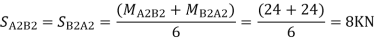
Similarly, 

- Analyse the given figure by portal Method
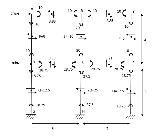
Mark point of contra flexure at centre of each beam& column.
Horizontal share is double at interior column.
Find p & q
P+2P+P=20
P=5kN
Q +2Q +Q=50
Q=12.5KN
Moment at column AD= =
=
MBE=
MCF=
MDG=MGD=
MEH=MHE=
MFI=MIF=
2. Analyse the given figure by portal method
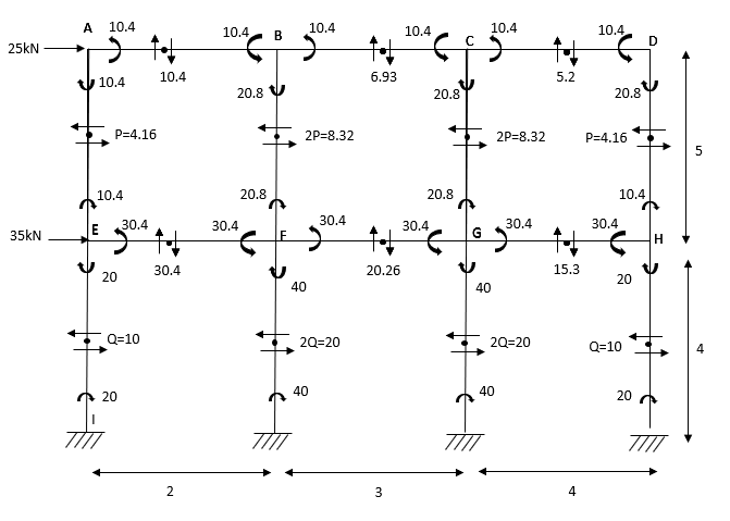
P+2P+2P+P=25
4P=25
P=4.16
Q+2Q+2Q+Q=60
6Q=60
Q=10KN
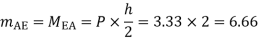
MAE=MEA= =4.16
=4.16
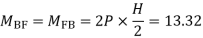
MBF=MFB=
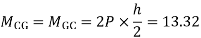
MCG=MGC=
MDH=MHD=
MEI=MIE= =10
=10
MFI=MIF=
MGK=MKG=
MHL=MLH=
Shear force
SFAB=20.8/2=10.4
SFBC=20.8/3=6.93
SFCD=20.8/4=5.2
SFEF=60.8/2=30.4
SFFG=60.8/3=20.26
SFGH=60.8/4=15.3
BMD

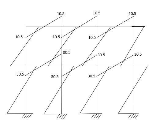
3. Analyze the given figure by portal method
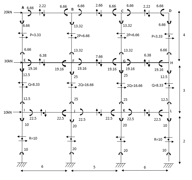
P=3.33 Q=3.33 R=10


4. Analyze the frame shown in figure below by portal method

1) Apply 1st assumption
2) Apply 2nd Assumption-> Horizontal shear is double at interior member
P+2p+p=25
P=6.25KN
Q+2Q+Q=25+50
Q=18.75KN
3) Moment at the end of column

4) Moment at the end of floor column


5) Moment at beam

6)Moment at end of beam


7)Shear force at (beam) floor
- Cantilever Method
The cantilever method is based on the following assumption:
Assumption
- There is a point of contraflexure at the centre of each member.
- The intensity of axial stress in each column storey is proportional to the horizontal distribution of that column from the centre of gravity of all columns of the storey under consideration.
Application:
- The method is more applicable to high rise structure since bending action is more predominant in these cases
- The column having different area of cross section can be taken into account.
Problem:
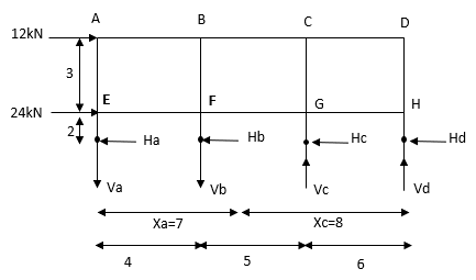
- Determine the approximate value of bending moment shearing force and axial force in a two bay two storey portal portal frame shown in fig. Using cantilever method assume equal cross sectional areas for all columns

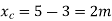
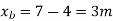
Step-1 Find centroidal distance
Take moment about A


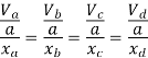
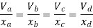
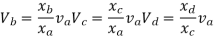
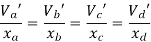
Step-2>As per 2nd assumption
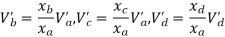
Vertical stresses in column are proportional to their absence from the C.G. Of the columns in that storey.
1> Consider top storey
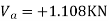
Assume  is downward &
 is upward.


Put  values
Taken about point of contra flexure i.e. at 0 point
Clockwise +ve Anticlockwise -ve
Upward +ve Downward -ve


Consider lowest storey
Assume  are downward
 are upward
As per 2nd assumption

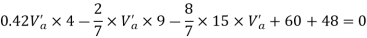
Take a moment about 0 point.


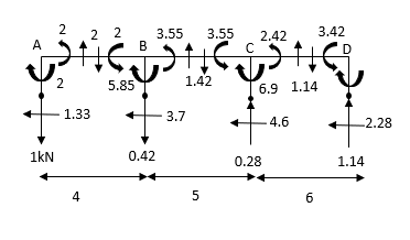
Step-3) To find S.F. In proof Beam

S.F. In AB=1KN
SF in BC=1+0.42=1.42
SF in CD=1+0.42-0.28=1.14

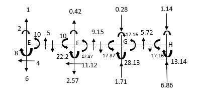
S.F. In EF=6-1=5KN
S.F. In FG=6+2.57+1-0.48=7.15KN
SF in GH=6+2.37-1.71-1-1-0.42+0.28=5.72KN
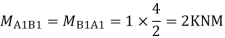
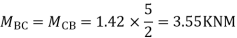
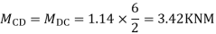
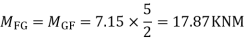
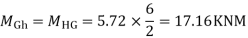
Step-4) To find Moment in roof beam
Formula => Moment in roof beam=S.F. In that Beam*Balt of Beam span


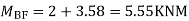
Ii> To find moment in floor beam


Step -5) To find Moment in column


Moment in column of floor beam


Step-6) S.F. In column
S.F. AE=2/1.5=1.33KNM
SF BF=5.55/1.5=3.7KN
S.F. CG=6.9/1.5=4.6KN
S.F. DH=3.42/1.5=2.28KN
S.F. In column EI=1.33*1.5+x+2=10
X=4KN
S.F. In column FJ=3.725*1.5+x+2=(17.85+10)
X=11.128KN
S.F. In column GK=4.667*1.5+x*2=(17.14+17.85)
X=13.99KN
S.F. In column HL=2.28*1.5+x+2=(17.142)
X=6.86KN
Key takeaways:
Steps:
- Find centroidal distance
- As per 2nd assumption
- To find S.F. In proof Beam
- To find Moment in roof beam
- To find Moment in column
- S.F. In column
References:
1. Structural Analysis by C.S. Reddy Mc. Graw Hill
2. Structural Analysis by R.C. Hibbler Pearson Education
Unit - 5
Slope defection method as applied to indeterminate beams
Unit - 5
Slope defection method as applied to indeterminate beams
1. Slope Deflection Method
- Slope=

- Deflection=

- Sign Convention

- Simply supported Beam

At support  form
form 
At the simply supported end
 is always zero.
 is always zero.
2. Cantilever beam
1.  =0 at the fixed end at force end

 At Fixed end
2. Slope deflection equation:
When a member of a structure is loaded, it deforms from its original position and internal forces are developed. The end moments can be expressed in terms of
(i) Fixed end moments (FEM) of the member due to transverse loading on the member
(ii) The slopes or rotations at the end
(iii) The end deflections or joint translations. These expressions are called as Slope-Deflection equations.
There are two slope deflection equations for each member.
These slope deflection equations are derived from superposition of the end moments caused by various actions and displacement.

Similarly

Where,
 = be the slope or rotation at joint A
 = be the slope or rotation at joint B.
 = be the end deflection or translation of joint A.
 = be the end deflection or translation of joint B.
 B/A = Relative translation of joint B with respect to joint A
 AB Angle between the unreformed member and the line joining the deflected joints.
Here  >
> Therefore
  B/A is positive
MAB = Moment at A of member AB
МВА = Moment at B of member BA
3. Fixed End Moments: Standard Cases Fixed End Moments
Standard Cases
1.
2.

3.


4.


5.


4. Derivation of slope Deflection Method
- In beam, a continuous beam ABCD, consider AB part and take fixed end moments and rotation at support as given below

As per the diagram
Slop deflection equations are


.
5. Types of numerical for slope deflection method
1. The beam is without sink (is zero.)
2. Beam with sink (is given)
3. Analyze of the frame without sink
4. Analyze the frame with the sink.
6. Steps for analysis of the slope deflection method
1. Find unknown slope .
.
2. Find fixed end moment
3. Apply the slope deflection equation.

4. Use the joint equilibrium equation at the joint.
5. Find final moments.
6. Find relation by equation &Draw SFI
7. Draw BMD


Hod


Step-III Apply equilibrium condition at joint


Step-IV Find final moments.

Step-V Find reaction

S.F. At A Take a moment at A is


SFD & BMD
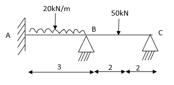
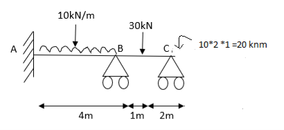
- Determine support moments & draw BMD for the beam shown by using S.D.

Step-I) Find Dki
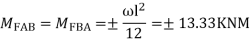
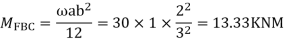
Step II) Find fixed end moments

For BC Beam

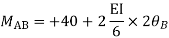
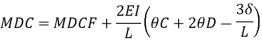
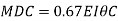
Step-III) Apply the SD equation
AB=>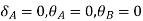


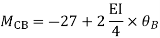
BC=>


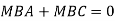
Step- IV) Apply equilibrium condition joint B


 ------- due to Hinge support
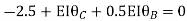


Put in equation (1) (2) (3) & (4)

Draw BMD Diagram
2. Analyze the continuous beam ABCD by S.D. Method draw BMD


Modify Diagram
Step- I) Fixed end moment


Apply S.D. Equation


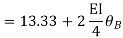


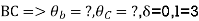

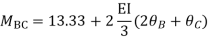


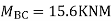
Member BC


Member CD
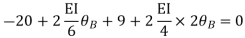
Step 4) To apply condition of equilibrium
At joint B
Adding equation 1and 2

Due to symmetry


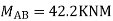
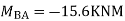
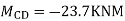
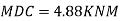
Step 5) To find end moments at joint


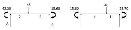
Step 6) Draw BMD and SFD

SFD
BMD


∑MA = MA – (10+Q)(1) = 0
MA = 10 + Q
∑F y = VA – (10 + Q) = 0 VA = 10 + Q
∑F x = HA = 0

Zone origin limits EI M ӘM/ӘQ
AB A 0 – 2 2EI (10+Q) x-(10+Q) x-1
CB C 0 – 1 EI - (10 + Q) -1
DC D 0 – 1 EI - (10 + Q) x - x
Δ D y = ∫20 (10x - 10)(x-1)dx/2EI + ∫10 -10(-1)dx/EI + ∫10 -10x(-x)dx/EI
= 3.33 + 10 + 3.33/EI
 Δ D y = 16.66/EI ( )
1. Portal method
This method is applicable for low rise structures. In low rise structures shear deformations are dominant, therefore this method simplifying assumptions regarding horizontal shear in column. Each bay of a structure as a portal frame and horizontal force is distributed equally among them. This means each interior column takes twice as much as the exterior column
Assumptions:
- The points of inflection or point of contra flexure are located at the mid height of each column. However for hinged column base it assumed at hinged column base
- The point of inflection are located at mid span of beam
- The horizontal shear at any floor is divided among all the basis that each interior column take twice as much as the exterior column
Steps
1) Assume first assumption -> mark point of contra flexure at centre of each column & beam
2) Apply 2nd assumption -> Horizontal shear is double at interior column.
3) Find P& Q force.
4) Find moment at beam = always same as moment of column.
5) Find shear force at beam=moment at 
Problems:
1) Analyse the given figure by portal method

Step 1) 1st Assumption-> Mark point of contraflexure of each member
Step 2) 2nd Assumption -> Interior Horizontal shear is double than (extreme) lost member.
P+2P+P=12
P=3KN
Q+2Q+Q=12+24
Q=9KN
Step 3) Moment at the end of column


Step 4) Moment at column

Step5) Moment at the end of roof Beam

Step 6) Moment at the end of floor Beam


Step 7) Shear force in Beam

Similarly, 
- Analyse the given figure by portal Method

Mark point of contra flexure at centre of each beam& column.
Horizontal share is double at interior column.
Find p & q
P+2P+P=20
P=5kN
Q +2Q +Q=50
Q=12.5KN
Moment at column AD= =
=
MBE=
MCF=
MDG=MGD=
MEH=MHE=
MFI=MIF=
2. Analyse the given figure by portal method

P+2P+2P+P=25
4P=25
P=4.16
Q+2Q+2Q+Q=60
6Q=60
Q=10KN
MAE=MEA= =4.16
=4.16
MBF=MFB=
MCG=MGC=
MDH=MHD=
MEI=MIE= =10
=10
MFI=MIF=
MGK=MKG=
MHL=MLH=
Shear force
SFAB=20.8/2=10.4
SFBC=20.8/3=6.93
SFCD=20.8/4=5.2
SFEF=60.8/2=30.4
SFFG=60.8/3=20.26
SFGH=60.8/4=15.3
BMD
3. Analyze the given figure by portal method

P=3.33 Q=3.33 R=10


4. Analyze the frame shown in figure below by portal method
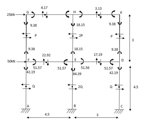
1) Apply 1st assumption
2) Apply 2nd Assumption-> Horizontal shear is double at interior member
P+2p+p=25
P=6.25KN
Q+2Q+Q=25+50
Q=18.75KN
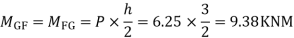
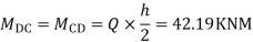
3) Moment at the end of column


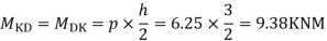
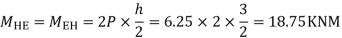
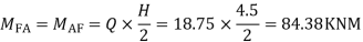
4) Moment at the end of floor column
5) Moment at beam

6)Moment at end of beam


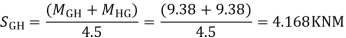
7)Shear force at (beam) floor

- Cantilever Method
The cantilever method is based on the following assumption:
Assumption
- There is a point of contraflexure at the centre of each member.
- The intensity of axial stress in each column storey is proportional to the horizontal distribution of that column from the centre of gravity of all columns of the storey under consideration.
Application:
- The method is more applicable to high rise structure since bending action is more predominant in these cases
- The column having different area of cross section can be taken into account.
Problem:
- Determine the approximate value of bending moment shearing force and axial force in a two bay two storey portal portal frame shown in fig. Using cantilever method assume equal cross sectional areas for all columns
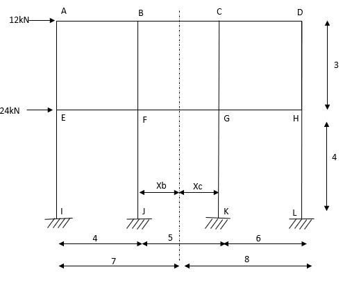
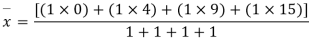
Step-1 Find centroidal distance
Take moment about A


Step-2>As per 2nd assumption
Vertical stresses in column are proportional to their absence from the C.G. Of the columns in that storey.
1> Consider top storey
Assume  is downward &
 is upward.

Put  values

Taken about point of contra flexure i.e. at 0 point
Clockwise +ve Anticlockwise -ve
Upward +ve Downward -ve


Consider lowest storey
Assume  are downward
 are upward

As per 2nd assumption

Take a moment about 0 point.


Step-3) To find S.F. In proof Beam
S.F. In AB=1KN
SF in BC=1+0.42=1.42
SF in CD=1+0.42-0.28=1.14
S.F. In EF=6-1=5KN
S.F. In FG=6+2.57+1-0.48=7.15KN
SF in GH=6+2.37-1.71-1-1-0.42+0.28=5.72KN
Step-4) To find Moment in roof beam
Formula => Moment in roof beam=S.F. In that Beam*Balt of Beam span
Ii> To find moment in floor beam

Step -5) To find Moment in column


Moment in column of floor beam


Step-6) S.F. In column
S.F. AE=2/1.5=1.33KNM
SF BF=5.55/1.5=3.7KN
S.F. CG=6.9/1.5=4.6KN
S.F. DH=3.42/1.5=2.28KN
S.F. In column EI=1.33*1.5+x+2=10
X=4KN
S.F. In column FJ=3.725*1.5+x+2=(17.85+10)
X=11.128KN
S.F. In column GK=4.667*1.5+x*2=(17.14+17.85)
X=13.99KN
S.F. In column HL=2.28*1.5+x+2=(17.142)
X=6.86KN
Key takeaways:
Steps:
- Find centroidal distance
- As per 2nd assumption
- To find S.F. In proof Beam
- To find Moment in roof beam
- To find Moment in column
- S.F. In column
References:
1. Structural Analysis by C.S. Reddy Mc. Graw Hill
2. Structural Analysis by R.C. Hibbler Pearson Education


