Unit - 4
Theodolite Survey
Components of Transit Theodolite (20"):
A transit theodolite essentially consists of following:
Key Takeaways:
The theodolite in which the telescope can be revolved through a complete revolution about its horizontal axis in a vertical plane is known as transit theodolite.
(a) Setting up the theodolite over a station:
(a) Centering the instrument over a station point
(b) Levelling the instrument approximately by the tripod legs
Centering the instrument over a station point:
(b) Levelling the instrument approximately by the tripod legs:

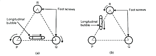
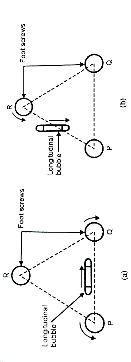
Fig.4.1: Levelling up with three-foot screws ‘PQR’
3. Rotate the telescope in 90° and then bring it over the third foot screw and bubble is brought in the center of its run by operating the third foot screw either clockwise or anti clockwise.
4. Again, bring the telescope back to its original position as it was in step 2 and check the centering of the bubble. Again, move the pair of foot screws either both outwards or both inwards simultaneously till the comes in the center of its run.
5. Again, turn the telescope through 90° over the third foot screw and check whether the bubble remains in center or not. If not, repeat these operations till the bubble remains in center for both positions of the telescope.
6. Now turn the telescope in any position through 360° and observe the bubble. If the bubble remains in center for all positions of the telescope, then telescope is now in accurate levelling and ready for further work of levelling.
(c)Focusing of eyepiece and object glass to eliminate the parallex:
(i) Focusing of eyepiece:
(ii) Focusing the object glass
Key Takeaways:
The following are the temporary adjustments:
Procedure:

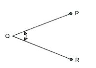
Fig.4.2: Measuring Horizontal angle
3. In order to set vernier A to the zero, loose the upper plate until the arrow of the vernier A approximately coincides with the zero of the horizontal circle. Clamp both plates together and by operating the slow-motion screw bring the arrow into exact coincidence with the zero of the circle. Both plates are now clamped.
4. Loose the lower clamp. Turn the instrument and then bisect the ranging rod at P. Tighten the clamp and bisect P exactly by using the lower slow-motion screw. The point of intersection of cross hairs should be brought into exact coincidence with the station point rod.
5. Check the reading of the vernier it should be same as above i.e., zero.
6. Now unclamp the upper plate and turn the telescope in clockwise direction until it bisects the ranging rod at R. Tight the upper clamp and by using the upper tangent screw, bisect the ranging rod at R exactly.
7. Read both verniers. The reading on vernier A gives the value of the angle PQR, whereas reading on vernier 'B' must be deducted from 180°, in order to get value of the angle PQR.
8. The mean of the two verniers reading will give required value of PQR.
9. Change the face of the instrument and repeat the whole process. The mean of the two vernier reading will give required value of PQR.
10. On all important work take both face observations to eliminate the errors due to imperfect adjustment of the instrument.
11. The mean of both face reading gives exact value of angle PQR which is free from all instrumental errors.
Procedure:

Fig.4.3: Measuring vertical angle
Key Takeaways:
A vertical angle is the angle between the inclined line of sight and the horizontal line. If the angle is above the horizontal line, it is called as angle of elevation it is always considered as positive angle. If the angle is below the horizontal line, it is called as angle of depression and it is always considered as negative angle.
Key Takeaways:
The technique of repetition used to degree traverse angles to a finer diploma of accuracy than that workable with the least be counted number of the vernier geared up at the theodolite.
References: