Unit - 2
Flow Through Pipes
Hydraulically smooth and rough pipes
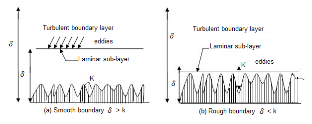
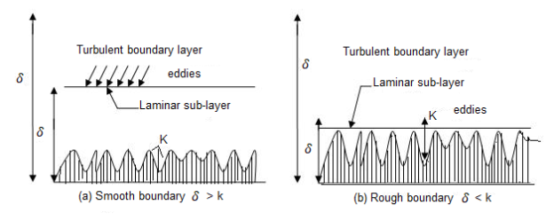
• When the common intensity okay of the floor irregularities is much less than laminar sub-layer of the floor δ is known as hydrodynamic best friend easy boundary.
• The eddy which shaped out of doors of the laminar sub-layer attempt to penetrate with inside the laminar sub-layer boundary is known as as easy boundary as proven in
• When the common intensity okay of the floor irregularities is more than laminar sub-layer of floor δ is known as hydrodynamic best friend tough boundary.
• The eddy which shaped out of doors of the laminar sub layer penetrates into the laminar sub-layer.
Such boundary is known as as tough boundary as proven in. By Nikuradse’s experiments, (1) When okay / δ < 0>6 , tough boundary. (3) When 0.25 < k> 100, tough boundary. (3) u.okay / v lies among four to 100, transition boundary.
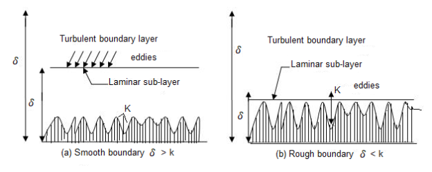
(a) Smooth Boundary input picture description here (b) Rough Boundary Let the common top of the irregularities projecting from the floor of boundary be denoted as ‘K’. Now, if the fee of ‘K’ is big for a boundary then the boundary is known as as Rough boundary.
This is the type of difficult and easy limitations primarily based totally on boundary traits. But for correct type waft and fluid traits also are considered. Hydro-dynamically easy boundary
1) For a turbulent waft analysis, the waft is split into elements or portions.
2) The first component includes a skinny layer of fluid with inside the on the spot neighborhood of the boundary, wherein the viscous shear strain is more potent while the shear strain because of turbulent is negligible. This is called laminar sub layer.
3) The 2d part of waft is the only wherein shear strain because of turbulence is better or big compared to the viscous shear and this region is known as as Turbulent region.
4) The region up to which or the peak up to which the impact of viscosity predominates is denoted through δ′.
5) So, we are able to say that if the common pace top ‘K’ is much less than ‘δ′’, then the boundary is known as Smooth boundary.
6) This occurs because, out of doors the laminar sub-layer the waft is turbulent and eddies of diverse sizes gift with inside the turbulent waft try and penetrate through the laminar sub-layer, however because of the top notch thickness of laminar sub-layer the eddies are not able to attain the floor irregularities and so the boundary behaves as easy boundary.
Hydro-dynamically difficult boundary
1) If the Reynolds range of the waft increases, the thickness of laminar sub-layer decreases.
2) If this occurs, then the common top ‘K’ of irregularities is above the laminar sub-layer and as a consequence the eddies gift will are available in touch with irregularities of the floor and lot of electricity might be lost.
3) Such a boundary is called Hydro-dynamically difficult boundary.
Frictional resistance to flow of fluid in smooth and rough pipes
The time period friction loss (or frictional loss) has some of unique meanings, relying on its context. In fluid go with the drift it's miles the top loss that takes place in a containment which includes a pipe or duct because of the impact of the fluid's viscosity close to the floor of the containment. In mechanical structures which includes inner combustion engines, the time period refers back to the strength misplaced in overcoming the friction among shifting surfaces. In economics, frictional loss is herbal and irrecoverable loss in a transaction or the cost(s) of doing enterprise too small to account for.
Contrast with treat in shipping, which made a widespread allowance for in any other case unaccounted for factors. Friction loss is a large engineering situation anywhere fluids are made to go with the drift, whether or not absolutely enclosed in a pipe or duct, or with a floor open to the air. Historically, it's miles a situation in aqueducts of all kinds, at some stage in human history. It is likewise applicable to sewer lines. Systematic have a look at strains lower back to Henry Darcy, an aqueduct engineer. Natural flows in river beds are essential to human activity; friction loss in a movement mattress has an impact on the peak of the go with the drift, specifically large at some point of flooding. The economies of pipelines for petrochemical transport are fantastically suffering from friction loss.
The Yamal–Europe pipeline consists of methane at a extent go with the drift charge of 32.3 × 10⁹ m3 of fuelling according to year, at Reynolds numbers more than 50 × 106 In hydropower applications, the power misplaced to pores and skin friction in flume and penstock isn't always to be had for beneficial work, say producing electricity. In refrigeration applications, power is expended pumping the coolant fluid through pipes or through the condenser. In cut up structures, the pipes wearing the coolant take the area of the air ducts in HVAC structures.
The loss of head, due to friction in pipes is given by,

In this equation, the value of coefficient of friction (f), should be known accurately for predicting the loss of head due to friction in pipes.
On the basis of dimensional analysis, it can be shown that the pressure loss in a straight pipe of diameter (D), length (L), roughness (K), average velocity (V¯), viscosity (‘μ’) and density of fluid (‘ρ’) is


Experimentally it was found that pressure drop is a function of L/D to the first power.


Key Takeaways:
- The eddy which shaped out of doors of the laminar sub layer penetrates into the laminar sub-layer.
- In economics, frictional loss is herbal and irrecoverable loss in a transaction or the cost(s) of doing enterprise too small to account for.
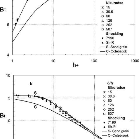
Nikuradze’s paintings achieved circa 1940 remains the gold general for the impact of roughness at the inner of a pipe. He used water and sand roughened pipes. He labeled round debris into slim particle length levels and fixed them onto the inner of diverse pipes of various diameters.
He then flowed water via the pipes at various waft fees and measured the strain differential throughout the ends of the pipe. By various the inner diameter of the pipes he became capable of create a vast variety of Reynolds variety waft. His effects have been exquisite for the roughened pipes however he additionally made a big mistake via way of means of seeking to healthy easy walled waft and roughened wall waft. This mistake nevertheless permeates the presently general idea of fluid dynamics inflicting a actual mess.
Johann Nikuradse (November 20, 1894 – July 18, 1979) became a Georgia-born German engineer and physicist. His brother, Alexander Nikuradse, became additionally a Germany-primarily based totally physicist and geopolitician recognized for his ties with Alfred Rosenberg and for his function in saving many Georgians at some stage in World War II.
He became born in Samtredia, Georgia (then a part of the Kutais Governorate, Imperial Russia) and studied at Kutaisi. In 1919, via the guidelines of the conspicuous Georgian student Petre Melikishvili, he went overseas for similarly studies. The 1921 Sovietization of Georgia precluded his go back to place of birth and Nikuradse naturalized as a German citizen.
He succeeded in placing himself in Prandtl's favour and as a consequence superior to the location of branch head. In spite of his near ties with the Nazi Party, Nikuradse came, withinside the early 1930s, beneathneath hearthplace of the institute's National Socialist Factory Cell Organization whose individuals accused him of spying for the Soviet Union and of stealing books from the institute. Prandtl to begin with defended Nikuradse, however became in the end pressured to brush aside him in 1934.
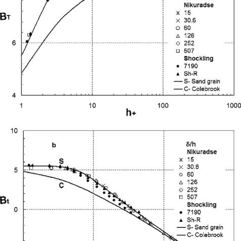
He then served as a professor on the University of Breslau (1934–1945), and an honorary professor on the Aachen Technical University due to the fact 1945. Nikuradse lived ordinarily in Göttingen and engaged in hydrodynamics. His quality recognized test became posted in Germany in 1933. Nikuradse cautiously measured the friction that a turbulent fluid reviews because it flows via a hard pipe. He used grains of sand with various roughnesses and observed that, the rougher the floor the extra the friction, and therefore a extra strain loss.
Moody’s chart
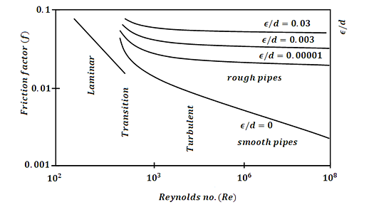
The Moody chart or Moody diagram is a graph in non-dimensional plot that relates the Darcy Weisbach friction factor (f), Reynolds number(Re) and Relative Roughness parameter(ϵ/d) for fully developed flows in a circular pipe.
It can be used to calculate the Head loss (hf)(hf) through pipes for a given flow rate or the flow rate through a pipe for a given head loss.
Head loss can be calculated using the Darcy Weisbach equation,

Where,
Density of the fluid
f Friction factor from the Moody chart
l Length of the pipe
V Average fluid velocity in the pipe
d Pipe diameter
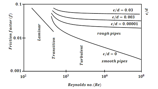
It may be visible from the discern that the graph includes three fluid go with the drift regimes: Laminar Flow (Re≤2300) Transition Flow (2300may be visible that the friction element for laminar go with the drift is a characteristic of Reynolds quantity by myself and is unbiased of relative roughness of the pipe. While the friction element for turbulent go with the drift is a characteristic of each Reynolds quantity and relative roughness of the pipe.
The friction element for transition go with the drift can normally be interpolated among the laminar price at Re = 2300 and the turbulent price at Re = 4000. The Relative Roughness parameter is the ratio of the imply top of roughness of the pipe to the pipe diameter (ϵ/d).
For hard pipes the fiction element will become unbiased of the Reynolds quantity and relies upon simplest at the relative roughness this occurs for the reason that thickness of the laminar sub layer reduces, absolutely exposing the floor roughness.
Darcy-Weisbach & Hazen- William’s equation for frictional head loss
Pressure Loss
The pressure loss (or major loss) in a pipe, tube or duct can be calculated with the Darcy-Weisbach equation
Δpmajor_loss = λ (l / dh) (ρf v2 / 2) (1)
Where
Δpmajor_loss = major (friction) pressure loss in fluid flow (Pa (N/m2), psf (lb/ft2))
λ = Darcy-Weisbach friction coefficient
l = length of duct or pipe (m, ft)
v = velocity of fluid (m/s, ft/s)
dh = hydraulic diameter (m, ft)
ρf = density of fluid (kg/m3, slugs/ft3)
Darcy-Weisbach Friction Loss Equation:

For square pipes (ducts), D=4A/P is called the hydraulic diameter. More statistics approximately hydraulic diameter may be discovered on our non-round to round pipe conversion page.
g = acceleration because of gravity = 32.174 ft/s2 = 9.806 m/s2.
The Hazen–Williams equation is an empirical dating which relates the go with the drift of water in a pipe with the bodily homes of the pipe and the stress drop due to friction. It is used with inside the layout of water pipe systems consisting of hearth place sprinkler systems, water deliver networks, and irrigation systems. It is known as after Allen Hazen and Gardner Stewart Williams.
The Hazen–Williams equation has the gain that the coefficient C isn't a characteristic of the Reynolds number, however it has the downside that it's miles most effective legitimate for water. Also, it does now no longer account for the temperature or viscosity of the water, and consequently is most effective legitimate at room temperature and traditional velocities.
Major loss (hf) is the strength (or head) loss (expressed in period units - consider it as strength in keeping with unit weight of fluid) because of friction among the shifting fluid and the duct. It is likewise called friction loss. The Darcy-Weisbach technique is normally taken into consideration greater correct than the Hazen-Williams technique. Additionally, the Darcy-Weisbach technique is legitimate for any liquid or gas; Hazen-Williams is handiest legitimate for water at regular temperatures (forty to seventy five oF).
Hazen-Williams is less difficult than Darcy-Weisbach for calculations in which you're fixing for flowrate, speed, or diameter. More Discussion and References. The Darcy-Weisbach calculation does now no longer test for unreasonable inputs along with poor values. All values need to be entered as positive.
Hydraulic gradient and energy gradient
In the pages at the float of a fluid via pipes, it's miles visible that there may be a lack of head. Whilst a number of that is because of the impact of unexpected contraction or expansions with inside the pipe diameter, pipe fittings including bends and valves and access and go out losses, a lack of capability head (i.e. The enter of the pipe is better than the outflow) a big element is because of the friction with inside the pipe (The Darcy Equation).
However in a pipe of uniform move section, there can be no lack of pace head and so the lack of Total Energy can be the end result of a loss in Pressure Head. Soil water capability is the using pressure at the back of water movement. The fundamental gain of the "capability" idea is that it presents a unified degree through which the water country may be evaluated at anytime and anywhere in the soil-plant-ecosystem continuum (Hillel, 1980).
Soil water is situation to some of forces. These forces encompass gravity, hydraulic pressure, the enchantment of the soil matrix for water, the presence of solutes, and the movement of outside fuelling pressure (Hillel, 1980). At any factor with inside the soil, general soil water capability is the sum of all the contributing forces.
Energy Gradient:
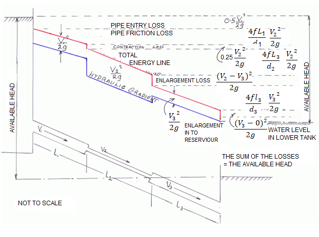
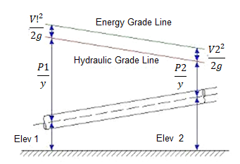
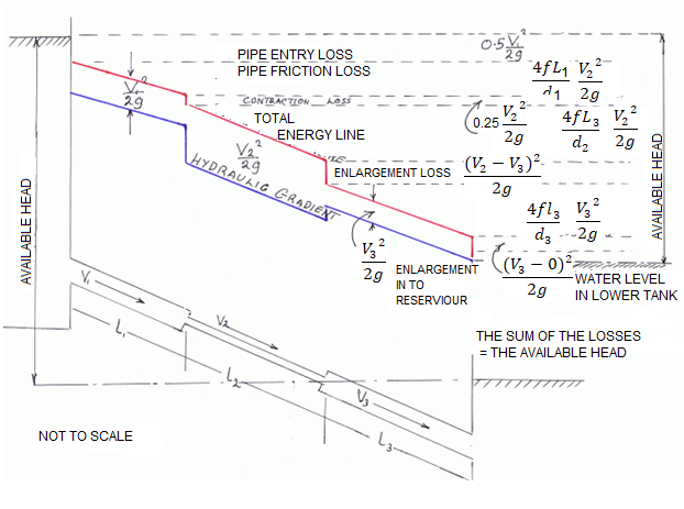
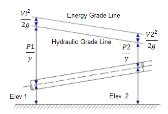
The term 'Energy grade line (EGL) (electricity line, electricity gradient)' because it applies to the location of reclamation may be described as ' The line displaying the overall electricity at any factor in a pipe. The general electricity with inside the glide of the phase as regards to a datum line is the sum of the elevation of the pipe centerline, the piezometric height (or stress head), and the speed head.
The electricity grade line will slope (drop) with inside the course of glide besides in which electricity is introduced with the aid of using mechanical devices. The line representing the elevation of the overall head of glide is the electricity line. The slope of the road is called the electricity gradient. A line that represents the elevation of electricity head (in toes or meters) of water flowing in a pipe, conduit, or channel. The line is drawn above the hydraulic grade line (gradient) a distance identical to the speed head (V2/2g) of the water flowing at every phase or factor alongside the pipe or channel.
Pipes in series and parallel
Pipe in Series:
Pipes are said to be in series if they are connected end to end (in continuation with each other) so that the fluid flows in a continuous line without any branching. The volume rate of flow through the pipes in series is the same throughout.
Suppose a pipe line consists of a number of pipes of different sizes and lengths.

Fig. Pipe in series
Let d1, d2, d3 be the diameters of the component pipes.
Let l1, l2, l3 be the lengths of these component pipes.
Let v1, v2, v3 be the velocities in these pipes.
Pipes connected in continuation as in this case are said to be connected in series. In this arrangement the rate of discharge Q is the same in all the pipes. Ignoring secondary losses the total loss of head is equal to the sum of the friction losses in the individual pipes.
If hf1, hf2, hf3 be the losses of head in the individual pipes the total loss of head hf is given by,
hf = hf1 + hf2 + hf3 = 4fl1/d1 . v12/2g + 4fl2/d2 . v22/2g + 4fl3/d3 . v32/2g
= fl1Q2/3.0257 d15 + fl2Q2/3.0257 d25+ fl3Q2/3.0257 d35
If the pipe coefficient of the pipes are different the above equation can be re arranged as
Fl/d5 = f1l1/d15 + f2l2/d25 + f3l3/d35 + ……
Equivalent Pipe Corresponding to a Given Set of Pipes in Series:
Let d1, d2, d3 be the diameters, and l1, l2, l3 be the lengths of the various pipes in a series connection. Let Q be the discharge. Let hf be the total loss of head.
Let d be the diameter of an equivalent pipe of length l to replace the compound pipe to pass the same discharge at the same loss of head.
hf = fl1Q2/3.0257 d15 + fl2Q2/3.0257 d25+ fl3Q2/3.0257 d35 = flQ2/3.0257 d5
l/d5 = l1/d15+ l2/d25 + l3/d35
The above relation is called Dupuit’s equation.
Equivalent Length of a Pipe with Intermediate Fittings:
Suppose a pipe of length I is provided with an intermediate fitting due to which the loss of head = k(v2/2g). Let Ie be the length of pipe, the friction loss due to which is equal to k(v2/2g).
4fle/d . v2/2g = k v2/2g le = kd/4f
This length may be added to the actual length of the pipe to determine the overall loss of head. Similarly if le1, le2, le3 . . . Etc. are the equivalent lengths of pipe corresponding to various fittings.
overall loss of head = 4f 
Pipes Connected in Parallel:
Pipes are said to be in parallel when they are so connected that the flow from a pipe branches or divides into two or more separate pipes and then reunite into a single pipe.
Suppose a main pipe branched at section 1-1 into two pipes of lengths l1 and l2 and diameters d1 and d2 and unite again at a section 2-2 to form a single pipe.
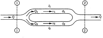
Then the two branch pipes are said to be connected in parallel.
In this arrangement the total discharge Q divides into components Q1 and Q2 along the branch pipes such that –
Q = Q1 + Q2
In this arrangement the loss of head from section 1-1 to section 2-2 is equal to the loss of head in any one of the branch pipes.
hf = hf1 = hf2


Hence the total discharge Q divides into components Q1 and Q2 satisfying the above equation.
Similarly when a number of pipes be connected in parallel, then also, the total loss of head in the system is equal to the loss of head in any one of the pipes.
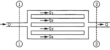
For example in the arrangement shown in Fig, the total loss of head in the system
= Loss of head from section
1 – 1 to section 2 – 2
hf = hf1 = hf2 = hf3 = hf4
The total discharge Q = Q1 + Q2 + Q3 + Q4

Branched pipes
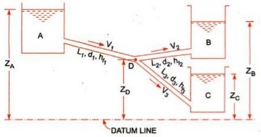
Flow through branched pipes can be described because the fluid glide through a piping machine wherein 3 or greater than 3 reservoirs can be linked with every different with the assist of pipes and could have one or a couple of junctions. Now we are able to see right here one parent as displayed right here.
Three reservoirs are linked right here with the assist of piping machine and this piping machine and reservoirs are linked with one unmarried junction i.e. junction D. In numerous branched pipe glide problems, we are able to have a few specs of branched piping machine and generally we are able to need to decide the glide of fluid through every pipe. Let us anticipate that we've got data approximately the statistics for period of pipes, diameter of pipes and coefficient if friction for every pipe and we want to locate the statistics for glide of water through every pipe.
Principle and equations used for solving such problems
We will have to recall the following principles and we will have to use following equations for securing the desired data for such problems.
- Continuity equation
- Bernoulli’s equation
- Darcy-Weisbach equation
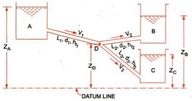
Let us consider that three reservoirs are A, B and C and piping system will have pipe 1, pipe 2 and pipe 3 and a single junction D as displayed above in figure.
Flow of water from reservoir A will take place to junction D and flow of water from junction D will be towards reservoir C.
Flow of water from junction D to reservoir B will only possible if piezometric head at D will be more than the piezometric head at B.
Let us consider the following terms from above figure.
ZA, ZB and ZC = Datum head at reservoir A, B and C respectively
V1, V2 and V3= Velocity of flow of water through pipe 1, 2 and 3 respectively
L1, L2 and L3 = length of pipe 1, 2 and 3 respectively
hf1, hf2 and hf3 = loss of head for pipe 1, 2 and 3 respectively
Let us now use the concept of Bernoulli’s equation for flow from A to D and we will have following equation as mentioned here.
ZA = ZD + PD/g + hf1
Let us now use the concept of Bernoulli’s equation for flow from D to B and we will have following equation as mentioned here.
ZD + PD/g = ZB + hf2
Let us now use the concept of Bernoulli’s equation for flow from D to C and we will have following equation as mentioned here.
ZD + PD/g = ZC + hf3
Now we will use the concept of continuity equation and we will have following equation as mentioned here.
Discharge through AD = Discharge through DB + Discharge through DC
Now as we can see that we are having with above four equations and we have to secure the value of V1, V2 and V3.
We will use above four equations to secure the value of flow of water through each pipe.
Further we will go ahead to find out the basic concept of power transmission through pipes, in the subject of fluid mechanics, with the help of our next post.
Siphon
There are main theories approximately how siphons motive liquid to glide uphill, towards gravity, without being pumped, and powered simplest with the aid of using gravity.
The conventional concept for hundreds of years became that gravity pulling the liquid down at the go out facet of the siphon ended in decreased strain on the pinnacle of the siphon. Then atmospheric strain became capable of push the liquid from the higher reservoir, up into the decreased strain on the pinnacle of the siphon, like in a barometer or ingesting straw, after which over. However, it's been verified that siphons can function in a vacuum and to heights exceeding the barometric top of the liquid.
Consequently, the concord anxiety concept of siphon operation has been advocated, wherein the liquid is pulled over the siphon in a manner much like the chain fountain. It want now no longer be one concept or the opposite this is accurate, however alternatively each theories can be accurate in unique occasions of ambient strain.
The atmospheric strain with gravity concept glaringly cannot give an explanation for siphons in vacuum, wherein there may be no giant atmospheric strain. But the concord anxiety with gravity concept cannot give an explanation for CO2 fuelling siphons, siphons operating no matter bubbles, and the flying droplet siphon, wherein gases do now no longer exert giant pulling forces, and beverages now no longer in touch cannot exert a cohesive anxiety force.
The chain version is a beneficial however now no longer absolutely correct conceptual version of a siphon. The chain version allows to apprehend how a siphon can purpose liquid to go with the drift uphill, powered most effective with the aid of using the downward pressure of gravity. A siphon can every now and then be concept of like a sequence striking over a pulley, with one stop of the chain piled on a better floor than the other. Since the duration of chain at the shorter aspect is lighter than the duration of chain at the taller aspect, the heavier chain at the taller aspect will pass down and pull up the chain at the lighter aspect.
Similar to a siphon, the chain version is glaringly simply powered with the aid of using gravity performing at the heavier aspect, and there's genuinely no violation of conservation of energy, due to the fact the chain is in the end simply shifting from a better to a decrease location, because the liquid does in a Even the falling lighter decrease leg from C to D can purpose the liquid of the heavier higher leg to go with the drift up and over into the decrease reservoir There are some of troubles with the chain version of a siphon, and information those variations allows to give an explanation for the real workings of siphons.
First, not like with inside the chain version of the siphon, it isn't always in reality the burden at the taller aspect in comparison to the shorter aspect that matters. Rather it's miles the distinction in peak from the reservoir surfaces to the pinnacle of the siphon, that determines the stability of pressure. For example, if the tube from the higher reservoir to the pinnacle of the siphon has a far large diameter than the taller segment of tube from the decrease reservoir to the pinnacle of the siphon, the shorter higher segment of the siphon might also additionally have a far large weight of liquid in it, and but the lighter extent of liquid with inside the down tube can pull liquid up the fatter up tube, and the siphon can feature
Transmission of power through pipes
Power is transmitted via pipes through flowing water or different drinks flowing via them. Power transmitted via pipes could be established over the subsequent elements as noted right here.
• Weight of the liquid flowing via the pipe
• Total head to be had on the give up of the pipe
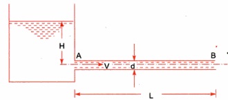
Now we are able to don't forget a tank with which a pipe AB is connected. Let us don't forget the subsequent phrases from figure.
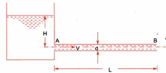
L = Length of the pipe
D = Diameter of the pipe
H = Total head available at the inlet of the pipe
V= Velocity of flow in pipe
hf = Loss of head due to friction
f = Co-efficient of friction
Power transmitted at the outlet of the pipe will be determined with the help of following formula as mentioned here.
P = g/1000 π/4. d2 V(H –  ) kW
) kW
Efficiency of power transmission
Efficiency of electricity transmission could be decided with the assist of following method as noted right here.


Condition for maximum transmission of power
Now we are able to locate right here the circumstance for max transmission of electricity and it may be secured through differentiating the equation of electricity transmitted at the hole of the pipe.


Above expression is the circumstance of most transmission of electricity. We can finish from above equation that electricity transmitted via a pipe could be most whilst the top loss because of friction could be one-0.33 of the full head at inlet.
Key Takeaways:
- The general electricity with inside the glide of the phase as regards to a datum line is the sum of the elevation of the pipe centerline, the piezometric height (or stress head), and the speed head.
- We will have to recall the following principles and we will have to use following equations for securing the desired data for such problems.
- There are main theories approximately how siphons motive liquid to glide uphill, towards gravity, without being pumped, and powered simplest with the aid of using gravity.
Hardy-Cross method of pipe networks
The technique became first posted in November 1936 via way of means of its namesake, Hardy Cross, a structural engineering professor on the University of Illinois at Urbana–Champaign. The Hardy Cross technique is an version of the Moment distribution technique, which became additionally advanced via way of means of Hardy Cross as a manner to decide the forces in statically indeterminate structures.
The advent of the Hardy Cross technique for reading pipe float networks revolutionized municipal water deliver design. Before the technique became introduced, fixing complicated pipe structures for distribution became extraordinarily tough because of the nonlinear courting among head loss and float. The technique became later made out of date via way of means of laptop fixing algorithms using the Newton–Raphson technique or different numerical strategies that get rid of the want to remedy nonlinear structures of equations via way of means of hand. The Hardy Cross technique is an utility of continuity of float and continuity of capacity to iteratively remedy for flows in a pipe community
In the case of pipe float, conservation of float method that the float in is same to the float out at every junction with inside the pipe. Conservation of capacity method that the whole directional head loss alongside any loop with inside the gadget is zero (assuming that a head loss counted towards the float is truly a head gain). Hardy Cross advanced strategies for fixing float networks. Each technique begins off evolved via way of means of preserving both continuity of float or capacity, after which iteratively solves for the different.
Piping networks have pretty a extensive variety of sensible applications, from water and fuel line distribution structures to aircon installations. Although easy issues, together with for instance, a unmarried department connecting reservoirs, can be solved analytically, greater complicated community issues want an iterative approach, ordinary to a virtual computer.
The maximum famous approach for fixing this sort of issues is the Hardy-Cross approach. Also, the pipe length, diameter, roughness and different key traits ought to be known. Before the approach became introduced, fixing complicated pipe structures for distribution became extraordinarily hard because of the nonlinear courting among head loss and glide.
Water distribution gadget fashions have grow to be very essential and sensible device for civil engineers. Models are frequently used to optimize the layout of latest distribution structures or examine fundamental extensions or changes to present distribution structures. The advent of the Hardy Cross approach for studying pipe glide networks revolutionized municipal water deliver layout (Pdhengineer.com, 2014). The Hardy Cross approach is commonly used because the pipe community evaluation with the aid of using maximum engineers.
The Hardy-Cross analysis is based on the principles that
- At each junction, the total inflow must be equal to total outflow.

2. Head balance criterion: algebraic sum of the head losses around any closed-loop is zero.

For a given pipe system, with known junction outflows, the Hardy-Cross method is an iterative procedure based on initially estimated flows in pipes. Estimated pipe flows are corrected with iteration until head losses in the clockwise direction and in the anticlockwise direction are equal within each loop.
- A trial distribution is made arbitrarily but in such a way that continuity equation is satisfied at each junction.
2. With the assumed value of Q, the head loss in each pipe is calculated according to the equation
hf = r Qn
Where
hf : head loss
r : head loss per unit flow
n : flow exponent
3. The net head loss around each loop is calculated.
4. If the net head loss due to assumed values of Q round the loop is zero, then the assumed values of Q in that loop are correct. If this is not the case, then the assumed values of Q are corrected by including a correction ï„Q for the flows till the circuit is balanced.
5. The correction factor ï„Q is obtained by

6. For turbulent flow, the value of n=2 and hence the correction factor becomes

7. If the value of ï„Q is positive, then it is added to the flow in the clockwise direction and subtracted from the flows in the anticlockwise direction.
8. After the correction have been applied to each pipe in a loop and to all loops, a second trial calculation is made for all loops. This procedure is repeated till ï„Q becomes negligible.
Water-hammer
Water hammer is a phenomenon which can arise in any piping gadget wherein valves are used to manipulate the float of beverages or steam. Water hammer is the end result of a stress surge, or high-stress shockwave that propagates via a piping gadget whilst a fluid in movement is pressured to extrude route or prevent abruptly.
This shockwave is likewise generally called a hydraulic surprise or hydraulic surge, and can be characterized through a marked banging or knocking sound at the pipes right now after shutoff. Water hammer can arise whilst an open valve unexpectedly closes, inflicting the water to slam into it, or whilst a pump unexpectedly shuts down and the float reverses route lower back to the pump. Since water is incompressible, the effect of the water consequences in a surprise wave that propagates at the velocity of sound among the valve and the following elbow with inside the piping gadget or in the column of water after the pump.
These unexpected stoppages of float and the ensuing will increase in stress from the surprise waves can motive full-size harm to the general piping gadget both because of a unique occasion or be cumulative harm happening over time. Ignoring water hammer can in the long run bring about the catastrophic failure of your float gadget.
The long-time period consequences of water hammer can include: Pump and Flow System Damage Repeated water hammer may motive full-size harm to pumps, present valves, and instruments, result in the catastrophic failure of casketed joints and growth joints, and have an effect on the integrity of pipe partitions and welded joints.
Pressure head due to sudden closure of valve.
The pressure rise due to water hammer depends upon
- The velocity of the flow in the water pipe
- The length of pipe
- Time to taken close the valve
- Elastic properties of the material of the pipe
In the following cases water hammer is been considered
- Gradual closure of the valve
- Sudden closure of valve when the pipe is rigid,
- Sudden closure of valve when the pipe is elastic
The time required for the pressure wave to travel from the valve to the reservoir and back to the valve is:
t = 2L/C
Where :
L = Length of the pipe (m), C = Speed of pressure wave (m/s)
If the valve time of closure is tc, then
- If tc > 2L/C the closure is considered gradual.
- If tc ≤ 2L/C the closure is considered Sudden.
When the water flowing in a protracted pipe line is all at once delivered to relaxation through the closure of a valve on the decrease give up or through any comparable cause, a surprising upward push in strain will arise because of the destruction of the momentum of the transferring frame of water. This will result in a strain wave or a surprise wave that's transmitted alongside the pipe. The speed of this strain wave is identical to speed of sound in water. The strain wave and the related pulsations or fluctuations in strain produce noise referred to as knocking or water hammer.
Such surprising strain rises have a knocking or hammering impact at the pipe wall. Pen shares of hydro-electric powered plants, water mains etc. are subjected to water hammer consequences because of surprising valve closures on the decrease ends. Such surprising strain rises produce sizeable hoop stresses with inside the pipe partitions and might from time to time result in pipe burst. Hence valves, on the decrease ends of such pipes need to be closed gradually.
The strain upward push produced because of surprising closure of valve relies upon on the rate of water with inside the pipe, the duration of the pipe, the c programming language of time taken to shut the valve and the pliability or stress of the pipe material. At the graduation of degree 1, the valve is closed and the layer of water near the valve is delivered to relaxation. This layer of water is compressed and therefore the strain will upward push through h and the pipe wall gets stretched. Successive layers are delivered to relaxation in succession and the strain rises for extra duration of pipe.
The hatched element represents water at relaxation. At the opposite give up of the pipe, is the reservoir R. Now the excessive strain wave actions with inside the upstream direction (i.e., in the direction of the reservoir) with a speed c, bringing the layers of water to relaxation, with inside the path of its passage.
Key takeaways:
- The Hardy Cross technique is a utility of continuity of float and continuity of capacity to iteratively remedy for flows in a pipe community
- The Hardy Cross approach is commonly used because the pipe community evaluation with the aid of using maximum engineers.
References:
1. Hydraulics & Fluid Mechanics- Dr.Modi& Dr. Seth
2. Fluid Mechanics-Streeter & Wylie
3. Fluid Mechanics- Dr. A.K.Jain
4. Fluid Mechanics through problems- Garde
5. Theory and applications of Fluid Mechanics- K. Subramanya
6. Foundation of Fluid Mechanics-Yuan
Unit - 2
Flow Through Pipes
Hydraulically smooth and rough pipes
• When the common intensity okay of the floor irregularities is much less than laminar sub-layer of the floor δ is known as hydrodynamic best friend easy boundary.
• The eddy which shaped out of doors of the laminar sub-layer attempt to penetrate with inside the laminar sub-layer boundary is known as as easy boundary as proven in
• When the common intensity okay of the floor irregularities is more than laminar sub-layer of floor δ is known as hydrodynamic best friend tough boundary.
• The eddy which shaped out of doors of the laminar sub layer penetrates into the laminar sub-layer.
Such boundary is known as as tough boundary as proven in. By Nikuradse’s experiments, (1) When okay / δ < 0>6 , tough boundary. (3) When 0.25 < k> 100, tough boundary. (3) u.okay / v lies among four to 100, transition boundary.
(a) Smooth Boundary input picture description here (b) Rough Boundary Let the common top of the irregularities projecting from the floor of boundary be denoted as ‘K’. Now, if the fee of ‘K’ is big for a boundary then the boundary is known as as Rough boundary.
This is the type of difficult and easy limitations primarily based totally on boundary traits. But for correct type waft and fluid traits also are considered. Hydro-dynamically easy boundary
1) For a turbulent waft analysis, the waft is split into elements or portions.
2) The first component includes a skinny layer of fluid with inside the on the spot neighborhood of the boundary, wherein the viscous shear strain is more potent while the shear strain because of turbulent is negligible. This is called laminar sub layer.
3) The 2d part of waft is the only wherein shear strain because of turbulence is better or big compared to the viscous shear and this region is known as as Turbulent region.
4) The region up to which or the peak up to which the impact of viscosity predominates is denoted through δ′.
5) So, we are able to say that if the common pace top ‘K’ is much less than ‘δ′’, then the boundary is known as Smooth boundary.
6) This occurs because, out of doors the laminar sub-layer the waft is turbulent and eddies of diverse sizes gift with inside the turbulent waft try and penetrate through the laminar sub-layer, however because of the top notch thickness of laminar sub-layer the eddies are not able to attain the floor irregularities and so the boundary behaves as easy boundary.
Hydro-dynamically difficult boundary
1) If the Reynolds range of the waft increases, the thickness of laminar sub-layer decreases.
2) If this occurs, then the common top ‘K’ of irregularities is above the laminar sub-layer and as a consequence the eddies gift will are available in touch with irregularities of the floor and lot of electricity might be lost.
3) Such a boundary is called Hydro-dynamically difficult boundary.
Frictional resistance to flow of fluid in smooth and rough pipes
The time period friction loss (or frictional loss) has some of unique meanings, relying on its context. In fluid go with the drift it's miles the top loss that takes place in a containment which includes a pipe or duct because of the impact of the fluid's viscosity close to the floor of the containment. In mechanical structures which includes inner combustion engines, the time period refers back to the strength misplaced in overcoming the friction among shifting surfaces. In economics, frictional loss is herbal and irrecoverable loss in a transaction or the cost(s) of doing enterprise too small to account for.
Contrast with treat in shipping, which made a widespread allowance for in any other case unaccounted for factors. Friction loss is a large engineering situation anywhere fluids are made to go with the drift, whether or not absolutely enclosed in a pipe or duct, or with a floor open to the air. Historically, it's miles a situation in aqueducts of all kinds, at some stage in human history. It is likewise applicable to sewer lines. Systematic have a look at strains lower back to Henry Darcy, an aqueduct engineer. Natural flows in river beds are essential to human activity; friction loss in a movement mattress has an impact on the peak of the go with the drift, specifically large at some point of flooding. The economies of pipelines for petrochemical transport are fantastically suffering from friction loss.
The Yamal–Europe pipeline consists of methane at a extent go with the drift charge of 32.3 × 10⁹ m3 of fuelling according to year, at Reynolds numbers more than 50 × 106 In hydropower applications, the power misplaced to pores and skin friction in flume and penstock isn't always to be had for beneficial work, say producing electricity. In refrigeration applications, power is expended pumping the coolant fluid through pipes or through the condenser. In cut up structures, the pipes wearing the coolant take the area of the air ducts in HVAC structures.
The loss of head, due to friction in pipes is given by,

In this equation, the value of coefficient of friction (f), should be known accurately for predicting the loss of head due to friction in pipes.
On the basis of dimensional analysis, it can be shown that the pressure loss in a straight pipe of diameter (D), length (L), roughness (K), average velocity (V¯), viscosity (‘μ’) and density of fluid (‘ρ’) is


Experimentally it was found that pressure drop is a function of L/D to the first power.


Key Takeaways:
- The eddy which shaped out of doors of the laminar sub layer penetrates into the laminar sub-layer.
- In economics, frictional loss is herbal and irrecoverable loss in a transaction or the cost(s) of doing enterprise too small to account for.
Nikuradze’s paintings achieved circa 1940 remains the gold general for the impact of roughness at the inner of a pipe. He used water and sand roughened pipes. He labeled round debris into slim particle length levels and fixed them onto the inner of diverse pipes of various diameters.
He then flowed water via the pipes at various waft fees and measured the strain differential throughout the ends of the pipe. By various the inner diameter of the pipes he became capable of create a vast variety of Reynolds variety waft. His effects have been exquisite for the roughened pipes however he additionally made a big mistake via way of means of seeking to healthy easy walled waft and roughened wall waft. This mistake nevertheless permeates the presently general idea of fluid dynamics inflicting a actual mess.
Johann Nikuradse (November 20, 1894 – July 18, 1979) became a Georgia-born German engineer and physicist. His brother, Alexander Nikuradse, became additionally a Germany-primarily based totally physicist and geopolitician recognized for his ties with Alfred Rosenberg and for his function in saving many Georgians at some stage in World War II.
He became born in Samtredia, Georgia (then a part of the Kutais Governorate, Imperial Russia) and studied at Kutaisi. In 1919, via the guidelines of the conspicuous Georgian student Petre Melikishvili, he went overseas for similarly studies. The 1921 Sovietization of Georgia precluded his go back to place of birth and Nikuradse naturalized as a German citizen.
He succeeded in placing himself in Prandtl's favour and as a consequence superior to the location of branch head. In spite of his near ties with the Nazi Party, Nikuradse came, withinside the early 1930s, beneathneath hearthplace of the institute's National Socialist Factory Cell Organization whose individuals accused him of spying for the Soviet Union and of stealing books from the institute. Prandtl to begin with defended Nikuradse, however became in the end pressured to brush aside him in 1934.
He then served as a professor on the University of Breslau (1934–1945), and an honorary professor on the Aachen Technical University due to the fact 1945. Nikuradse lived ordinarily in Göttingen and engaged in hydrodynamics. His quality recognized test became posted in Germany in 1933. Nikuradse cautiously measured the friction that a turbulent fluid reviews because it flows via a hard pipe. He used grains of sand with various roughnesses and observed that, the rougher the floor the extra the friction, and therefore a extra strain loss.
Moody’s chart
The Moody chart or Moody diagram is a graph in non-dimensional plot that relates the Darcy Weisbach friction factor (f), Reynolds number(Re) and Relative Roughness parameter(ϵ/d) for fully developed flows in a circular pipe.
It can be used to calculate the Head loss (hf)(hf) through pipes for a given flow rate or the flow rate through a pipe for a given head loss.
Head loss can be calculated using the Darcy Weisbach equation,

Where,
Density of the fluid
f Friction factor from the Moody chart
l Length of the pipe
V Average fluid velocity in the pipe
d Pipe diameter
It may be visible from the discern that the graph includes three fluid go with the drift regimes: Laminar Flow (Re≤2300) Transition Flow (2300may be visible that the friction element for laminar go with the drift is a characteristic of Reynolds quantity by myself and is unbiased of relative roughness of the pipe. While the friction element for turbulent go with the drift is a characteristic of each Reynolds quantity and relative roughness of the pipe.
The friction element for transition go with the drift can normally be interpolated among the laminar price at Re = 2300 and the turbulent price at Re = 4000. The Relative Roughness parameter is the ratio of the imply top of roughness of the pipe to the pipe diameter (ϵ/d).
For hard pipes the fiction element will become unbiased of the Reynolds quantity and relies upon simplest at the relative roughness this occurs for the reason that thickness of the laminar sub layer reduces, absolutely exposing the floor roughness.
Darcy-Weisbach & Hazen- William’s equation for frictional head loss
Pressure Loss
The pressure loss (or major loss) in a pipe, tube or duct can be calculated with the Darcy-Weisbach equation
Δpmajor_loss = λ (l / dh) (ρf v2 / 2) (1)
Where
Δpmajor_loss = major (friction) pressure loss in fluid flow (Pa (N/m2), psf (lb/ft2))
λ = Darcy-Weisbach friction coefficient
l = length of duct or pipe (m, ft)
v = velocity of fluid (m/s, ft/s)
dh = hydraulic diameter (m, ft)
ρf = density of fluid (kg/m3, slugs/ft3)
Darcy-Weisbach Friction Loss Equation:

For square pipes (ducts), D=4A/P is called the hydraulic diameter. More statistics approximately hydraulic diameter may be discovered on our non-round to round pipe conversion page.
g = acceleration because of gravity = 32.174 ft/s2 = 9.806 m/s2.
The Hazen–Williams equation is an empirical dating which relates the go with the drift of water in a pipe with the bodily homes of the pipe and the stress drop due to friction. It is used with inside the layout of water pipe systems consisting of hearth place sprinkler systems, water deliver networks, and irrigation systems. It is known as after Allen Hazen and Gardner Stewart Williams.
The Hazen–Williams equation has the gain that the coefficient C isn't a characteristic of the Reynolds number, however it has the downside that it's miles most effective legitimate for water. Also, it does now no longer account for the temperature or viscosity of the water, and consequently is most effective legitimate at room temperature and traditional velocities.
Major loss (hf) is the strength (or head) loss (expressed in period units - consider it as strength in keeping with unit weight of fluid) because of friction among the shifting fluid and the duct. It is likewise called friction loss. The Darcy-Weisbach technique is normally taken into consideration greater correct than the Hazen-Williams technique. Additionally, the Darcy-Weisbach technique is legitimate for any liquid or gas; Hazen-Williams is handiest legitimate for water at regular temperatures (forty to seventy five oF).
Hazen-Williams is less difficult than Darcy-Weisbach for calculations in which you're fixing for flowrate, speed, or diameter. More Discussion and References. The Darcy-Weisbach calculation does now no longer test for unreasonable inputs along with poor values. All values need to be entered as positive.
Hydraulic gradient and energy gradient
In the pages at the float of a fluid via pipes, it's miles visible that there may be a lack of head. Whilst a number of that is because of the impact of unexpected contraction or expansions with inside the pipe diameter, pipe fittings including bends and valves and access and go out losses, a lack of capability head (i.e. The enter of the pipe is better than the outflow) a big element is because of the friction with inside the pipe (The Darcy Equation).
However in a pipe of uniform move section, there can be no lack of pace head and so the lack of Total Energy can be the end result of a loss in Pressure Head. Soil water capability is the using pressure at the back of water movement. The fundamental gain of the "capability" idea is that it presents a unified degree through which the water country may be evaluated at anytime and anywhere in the soil-plant-ecosystem continuum (Hillel, 1980).
Soil water is situation to some of forces. These forces encompass gravity, hydraulic pressure, the enchantment of the soil matrix for water, the presence of solutes, and the movement of outside fuelling pressure (Hillel, 1980). At any factor with inside the soil, general soil water capability is the sum of all the contributing forces.
Energy Gradient:
The term 'Energy grade line (EGL) (electricity line, electricity gradient)' because it applies to the location of reclamation may be described as ' The line displaying the overall electricity at any factor in a pipe. The general electricity with inside the glide of the phase as regards to a datum line is the sum of the elevation of the pipe centerline, the piezometric height (or stress head), and the speed head.
The electricity grade line will slope (drop) with inside the course of glide besides in which electricity is introduced with the aid of using mechanical devices. The line representing the elevation of the overall head of glide is the electricity line. The slope of the road is called the electricity gradient. A line that represents the elevation of electricity head (in toes or meters) of water flowing in a pipe, conduit, or channel. The line is drawn above the hydraulic grade line (gradient) a distance identical to the speed head (V2/2g) of the water flowing at every phase or factor alongside the pipe or channel.
Pipes in series and parallel
Pipe in Series:
Pipes are said to be in series if they are connected end to end (in continuation with each other) so that the fluid flows in a continuous line without any branching. The volume rate of flow through the pipes in series is the same throughout.
Suppose a pipe line consists of a number of pipes of different sizes and lengths.

Fig. Pipe in series
Let d1, d2, d3 be the diameters of the component pipes.
Let l1, l2, l3 be the lengths of these component pipes.
Let v1, v2, v3 be the velocities in these pipes.
Pipes connected in continuation as in this case are said to be connected in series. In this arrangement the rate of discharge Q is the same in all the pipes. Ignoring secondary losses the total loss of head is equal to the sum of the friction losses in the individual pipes.
If hf1, hf2, hf3 be the losses of head in the individual pipes the total loss of head hf is given by,
hf = hf1 + hf2 + hf3 = 4fl1/d1 . v12/2g + 4fl2/d2 . v22/2g + 4fl3/d3 . v32/2g
= fl1Q2/3.0257 d15 + fl2Q2/3.0257 d25+ fl3Q2/3.0257 d35
If the pipe coefficient of the pipes are different the above equation can be re arranged as
Fl/d5 = f1l1/d15 + f2l2/d25 + f3l3/d35 + ……
Equivalent Pipe Corresponding to a Given Set of Pipes in Series:
Let d1, d2, d3 be the diameters, and l1, l2, l3 be the lengths of the various pipes in a series connection. Let Q be the discharge. Let hf be the total loss of head.
Let d be the diameter of an equivalent pipe of length l to replace the compound pipe to pass the same discharge at the same loss of head.
hf = fl1Q2/3.0257 d15 + fl2Q2/3.0257 d25+ fl3Q2/3.0257 d35 = flQ2/3.0257 d5
l/d5 = l1/d15+ l2/d25 + l3/d35
The above relation is called Dupuit’s equation.
Equivalent Length of a Pipe with Intermediate Fittings:
Suppose a pipe of length I is provided with an intermediate fitting due to which the loss of head = k(v2/2g). Let Ie be the length of pipe, the friction loss due to which is equal to k(v2/2g).
4fle/d . v2/2g = k v2/2g le = kd/4f
This length may be added to the actual length of the pipe to determine the overall loss of head. Similarly if le1, le2, le3 . . . Etc. are the equivalent lengths of pipe corresponding to various fittings.
overall loss of head = 4f 
Pipes Connected in Parallel:
Pipes are said to be in parallel when they are so connected that the flow from a pipe branches or divides into two or more separate pipes and then reunite into a single pipe.
Suppose a main pipe branched at section 1-1 into two pipes of lengths l1 and l2 and diameters d1 and d2 and unite again at a section 2-2 to form a single pipe.
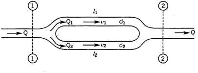
Then the two branch pipes are said to be connected in parallel.
In this arrangement the total discharge Q divides into components Q1 and Q2 along the branch pipes such that –
Q = Q1 + Q2
In this arrangement the loss of head from section 1-1 to section 2-2 is equal to the loss of head in any one of the branch pipes.
hf = hf1 = hf2


Hence the total discharge Q divides into components Q1 and Q2 satisfying the above equation.
Similarly when a number of pipes be connected in parallel, then also, the total loss of head in the system is equal to the loss of head in any one of the pipes.
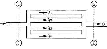
For example in the arrangement shown in Fig, the total loss of head in the system
= Loss of head from section
1 – 1 to section 2 – 2
hf = hf1 = hf2 = hf3 = hf4
The total discharge Q = Q1 + Q2 + Q3 + Q4

Branched pipes
Flow through branched pipes can be described because the fluid glide through a piping machine wherein 3 or greater than 3 reservoirs can be linked with every different with the assist of pipes and could have one or a couple of junctions. Now we are able to see right here one parent as displayed right here.
Three reservoirs are linked right here with the assist of piping machine and this piping machine and reservoirs are linked with one unmarried junction i.e. junction D. In numerous branched pipe glide problems, we are able to have a few specs of branched piping machine and generally we are able to need to decide the glide of fluid through every pipe. Let us anticipate that we've got data approximately the statistics for period of pipes, diameter of pipes and coefficient if friction for every pipe and we want to locate the statistics for glide of water through every pipe.
Principle and equations used for solving such problems
We will have to recall the following principles and we will have to use following equations for securing the desired data for such problems.
- Continuity equation
- Bernoulli’s equation
- Darcy-Weisbach equation
Let us consider that three reservoirs are A, B and C and piping system will have pipe 1, pipe 2 and pipe 3 and a single junction D as displayed above in figure.
Flow of water from reservoir A will take place to junction D and flow of water from junction D will be towards reservoir C.
Flow of water from junction D to reservoir B will only possible if piezometric head at D will be more than the piezometric head at B.
Let us consider the following terms from above figure.
ZA, ZB and ZC = Datum head at reservoir A, B and C respectively
V1, V2 and V3= Velocity of flow of water through pipe 1, 2 and 3 respectively
L1, L2 and L3 = length of pipe 1, 2 and 3 respectively
hf1, hf2 and hf3 = loss of head for pipe 1, 2 and 3 respectively
Let us now use the concept of Bernoulli’s equation for flow from A to D and we will have following equation as mentioned here.
ZA = ZD + PD/g + hf1
Let us now use the concept of Bernoulli’s equation for flow from D to B and we will have following equation as mentioned here.
ZD + PD/g = ZB + hf2
Let us now use the concept of Bernoulli’s equation for flow from D to C and we will have following equation as mentioned here.
ZD + PD/g = ZC + hf3
Now we will use the concept of continuity equation and we will have following equation as mentioned here.
Discharge through AD = Discharge through DB + Discharge through DC
Now as we can see that we are having with above four equations and we have to secure the value of V1, V2 and V3.
We will use above four equations to secure the value of flow of water through each pipe.
Further we will go ahead to find out the basic concept of power transmission through pipes, in the subject of fluid mechanics, with the help of our next post.
Siphon
There are main theories approximately how siphons motive liquid to glide uphill, towards gravity, without being pumped, and powered simplest with the aid of using gravity.
The conventional concept for hundreds of years became that gravity pulling the liquid down at the go out facet of the siphon ended in decreased strain on the pinnacle of the siphon. Then atmospheric strain became capable of push the liquid from the higher reservoir, up into the decreased strain on the pinnacle of the siphon, like in a barometer or ingesting straw, after which over. However, it's been verified that siphons can function in a vacuum and to heights exceeding the barometric top of the liquid.
Consequently, the concord anxiety concept of siphon operation has been advocated, wherein the liquid is pulled over the siphon in a manner much like the chain fountain. It want now no longer be one concept or the opposite this is accurate, however alternatively each theories can be accurate in unique occasions of ambient strain.
The atmospheric strain with gravity concept glaringly cannot give an explanation for siphons in vacuum, wherein there may be no giant atmospheric strain. But the concord anxiety with gravity concept cannot give an explanation for CO2 fuelling siphons, siphons operating no matter bubbles, and the flying droplet siphon, wherein gases do now no longer exert giant pulling forces, and beverages now no longer in touch cannot exert a cohesive anxiety force.
The chain version is a beneficial however now no longer absolutely correct conceptual version of a siphon. The chain version allows to apprehend how a siphon can purpose liquid to go with the drift uphill, powered most effective with the aid of using the downward pressure of gravity. A siphon can every now and then be concept of like a sequence striking over a pulley, with one stop of the chain piled on a better floor than the other. Since the duration of chain at the shorter aspect is lighter than the duration of chain at the taller aspect, the heavier chain at the taller aspect will pass down and pull up the chain at the lighter aspect.
Similar to a siphon, the chain version is glaringly simply powered with the aid of using gravity performing at the heavier aspect, and there's genuinely no violation of conservation of energy, due to the fact the chain is in the end simply shifting from a better to a decrease location, because the liquid does in a Even the falling lighter decrease leg from C to D can purpose the liquid of the heavier higher leg to go with the drift up and over into the decrease reservoir There are some of troubles with the chain version of a siphon, and information those variations allows to give an explanation for the real workings of siphons.
First, not like with inside the chain version of the siphon, it isn't always in reality the burden at the taller aspect in comparison to the shorter aspect that matters. Rather it's miles the distinction in peak from the reservoir surfaces to the pinnacle of the siphon, that determines the stability of pressure. For example, if the tube from the higher reservoir to the pinnacle of the siphon has a far large diameter than the taller segment of tube from the decrease reservoir to the pinnacle of the siphon, the shorter higher segment of the siphon might also additionally have a far large weight of liquid in it, and but the lighter extent of liquid with inside the down tube can pull liquid up the fatter up tube, and the siphon can feature
Transmission of power through pipes
Power is transmitted via pipes through flowing water or different drinks flowing via them. Power transmitted via pipes could be established over the subsequent elements as noted right here.
• Weight of the liquid flowing via the pipe
• Total head to be had on the give up of the pipe
Now we are able to don't forget a tank with which a pipe AB is connected. Let us don't forget the subsequent phrases from figure.
L = Length of the pipe
D = Diameter of the pipe
H = Total head available at the inlet of the pipe
V= Velocity of flow in pipe
hf = Loss of head due to friction
f = Co-efficient of friction
Power transmitted at the outlet of the pipe will be determined with the help of following formula as mentioned here.
P = g/1000 π/4. d2 V(H –  ) kW
) kW
Efficiency of power transmission
Efficiency of electricity transmission could be decided with the assist of following method as noted right here.


Condition for maximum transmission of power
Now we are able to locate right here the circumstance for max transmission of electricity and it may be secured through differentiating the equation of electricity transmitted at the hole of the pipe.


Above expression is the circumstance of most transmission of electricity. We can finish from above equation that electricity transmitted via a pipe could be most whilst the top loss because of friction could be one-0.33 of the full head at inlet.
Key Takeaways:
- The general electricity with inside the glide of the phase as regards to a datum line is the sum of the elevation of the pipe centerline, the piezometric height (or stress head), and the speed head.
- We will have to recall the following principles and we will have to use following equations for securing the desired data for such problems.
- There are main theories approximately how siphons motive liquid to glide uphill, towards gravity, without being pumped, and powered simplest with the aid of using gravity.
Hardy-Cross method of pipe networks
The technique became first posted in November 1936 via way of means of its namesake, Hardy Cross, a structural engineering professor on the University of Illinois at Urbana–Champaign. The Hardy Cross technique is an version of the Moment distribution technique, which became additionally advanced via way of means of Hardy Cross as a manner to decide the forces in statically indeterminate structures.
The advent of the Hardy Cross technique for reading pipe float networks revolutionized municipal water deliver design. Before the technique became introduced, fixing complicated pipe structures for distribution became extraordinarily tough because of the nonlinear courting among head loss and float. The technique became later made out of date via way of means of laptop fixing algorithms using the Newton–Raphson technique or different numerical strategies that get rid of the want to remedy nonlinear structures of equations via way of means of hand. The Hardy Cross technique is an utility of continuity of float and continuity of capacity to iteratively remedy for flows in a pipe community
In the case of pipe float, conservation of float method that the float in is same to the float out at every junction with inside the pipe. Conservation of capacity method that the whole directional head loss alongside any loop with inside the gadget is zero (assuming that a head loss counted towards the float is truly a head gain). Hardy Cross advanced strategies for fixing float networks. Each technique begins off evolved via way of means of preserving both continuity of float or capacity, after which iteratively solves for the different.
Piping networks have pretty a extensive variety of sensible applications, from water and fuel line distribution structures to aircon installations. Although easy issues, together with for instance, a unmarried department connecting reservoirs, can be solved analytically, greater complicated community issues want an iterative approach, ordinary to a virtual computer.
The maximum famous approach for fixing this sort of issues is the Hardy-Cross approach. Also, the pipe length, diameter, roughness and different key traits ought to be known. Before the approach became introduced, fixing complicated pipe structures for distribution became extraordinarily hard because of the nonlinear courting among head loss and glide.
Water distribution gadget fashions have grow to be very essential and sensible device for civil engineers. Models are frequently used to optimize the layout of latest distribution structures or examine fundamental extensions or changes to present distribution structures. The advent of the Hardy Cross approach for studying pipe glide networks revolutionized municipal water deliver layout (Pdhengineer.com, 2014). The Hardy Cross approach is commonly used because the pipe community evaluation with the aid of using maximum engineers.
The Hardy-Cross analysis is based on the principles that
- At each junction, the total inflow must be equal to total outflow.

2. Head balance criterion: algebraic sum of the head losses around any closed-loop is zero.

For a given pipe system, with known junction outflows, the Hardy-Cross method is an iterative procedure based on initially estimated flows in pipes. Estimated pipe flows are corrected with iteration until head losses in the clockwise direction and in the anticlockwise direction are equal within each loop.
- A trial distribution is made arbitrarily but in such a way that continuity equation is satisfied at each junction.
2. With the assumed value of Q, the head loss in each pipe is calculated according to the equation
hf = r Qn
Where
hf : head loss
r : head loss per unit flow
n : flow exponent
3. The net head loss around each loop is calculated.
4. If the net head loss due to assumed values of Q round the loop is zero, then the assumed values of Q in that loop are correct. If this is not the case, then the assumed values of Q are corrected by including a correction ï„Q for the flows till the circuit is balanced.
5. The correction factor ï„Q is obtained by

6. For turbulent flow, the value of n=2 and hence the correction factor becomes

7. If the value of ï„Q is positive, then it is added to the flow in the clockwise direction and subtracted from the flows in the anticlockwise direction.
8. After the correction have been applied to each pipe in a loop and to all loops, a second trial calculation is made for all loops. This procedure is repeated till ï„Q becomes negligible.
Water-hammer
Water hammer is a phenomenon which can arise in any piping gadget wherein valves are used to manipulate the float of beverages or steam. Water hammer is the end result of a stress surge, or high-stress shockwave that propagates via a piping gadget whilst a fluid in movement is pressured to extrude route or prevent abruptly.
This shockwave is likewise generally called a hydraulic surprise or hydraulic surge, and can be characterized through a marked banging or knocking sound at the pipes right now after shutoff. Water hammer can arise whilst an open valve unexpectedly closes, inflicting the water to slam into it, or whilst a pump unexpectedly shuts down and the float reverses route lower back to the pump. Since water is incompressible, the effect of the water consequences in a surprise wave that propagates at the velocity of sound among the valve and the following elbow with inside the piping gadget or in the column of water after the pump.
These unexpected stoppages of float and the ensuing will increase in stress from the surprise waves can motive full-size harm to the general piping gadget both because of a unique occasion or be cumulative harm happening over time. Ignoring water hammer can in the long run bring about the catastrophic failure of your float gadget.
The long-time period consequences of water hammer can include: Pump and Flow System Damage Repeated water hammer may motive full-size harm to pumps, present valves, and instruments, result in the catastrophic failure of casketed joints and growth joints, and have an effect on the integrity of pipe partitions and welded joints.
Pressure head due to sudden closure of valve.
The pressure rise due to water hammer depends upon
- The velocity of the flow in the water pipe
- The length of pipe
- Time to taken close the valve
- Elastic properties of the material of the pipe
In the following cases water hammer is been considered
- Gradual closure of the valve
- Sudden closure of valve when the pipe is rigid,
- Sudden closure of valve when the pipe is elastic
The time required for the pressure wave to travel from the valve to the reservoir and back to the valve is:
t = 2L/C
Where :
L = Length of the pipe (m), C = Speed of pressure wave (m/s)
If the valve time of closure is tc, then
- If tc > 2L/C the closure is considered gradual.
- If tc ≤ 2L/C the closure is considered Sudden.
When the water flowing in a protracted pipe line is all at once delivered to relaxation through the closure of a valve on the decrease give up or through any comparable cause, a surprising upward push in strain will arise because of the destruction of the momentum of the transferring frame of water. This will result in a strain wave or a surprise wave that's transmitted alongside the pipe. The speed of this strain wave is identical to speed of sound in water. The strain wave and the related pulsations or fluctuations in strain produce noise referred to as knocking or water hammer.
Such surprising strain rises have a knocking or hammering impact at the pipe wall. Pen shares of hydro-electric powered plants, water mains etc. are subjected to water hammer consequences because of surprising valve closures on the decrease ends. Such surprising strain rises produce sizeable hoop stresses with inside the pipe partitions and might from time to time result in pipe burst. Hence valves, on the decrease ends of such pipes need to be closed gradually.
The strain upward push produced because of surprising closure of valve relies upon on the rate of water with inside the pipe, the duration of the pipe, the c programming language of time taken to shut the valve and the pliability or stress of the pipe material. At the graduation of degree 1, the valve is closed and the layer of water near the valve is delivered to relaxation. This layer of water is compressed and therefore the strain will upward push through h and the pipe wall gets stretched. Successive layers are delivered to relaxation in succession and the strain rises for extra duration of pipe.
The hatched element represents water at relaxation. At the opposite give up of the pipe, is the reservoir R. Now the excessive strain wave actions with inside the upstream direction (i.e., in the direction of the reservoir) with a speed c, bringing the layers of water to relaxation, with inside the path of its passage.
Key takeaways:
- The Hardy Cross technique is a utility of continuity of float and continuity of capacity to iteratively remedy for flows in a pipe community
- The Hardy Cross approach is commonly used because the pipe community evaluation with the aid of using maximum engineers.
References:
1. Hydraulics & Fluid Mechanics- Dr.Modi& Dr. Seth
2. Fluid Mechanics-Streeter & Wylie
3. Fluid Mechanics- Dr. A.K.Jain
4. Fluid Mechanics through problems- Garde
5. Theory and applications of Fluid Mechanics- K. Subramanya
6. Foundation of Fluid Mechanics-Yuan
Unit - 2
Flow Through Pipes
Hydraulically smooth and rough pipes
• When the common intensity okay of the floor irregularities is much less than laminar sub-layer of the floor δ is known as hydrodynamic best friend easy boundary.
• The eddy which shaped out of doors of the laminar sub-layer attempt to penetrate with inside the laminar sub-layer boundary is known as as easy boundary as proven in
• When the common intensity okay of the floor irregularities is more than laminar sub-layer of floor δ is known as hydrodynamic best friend tough boundary.
• The eddy which shaped out of doors of the laminar sub layer penetrates into the laminar sub-layer.
Such boundary is known as as tough boundary as proven in. By Nikuradse’s experiments, (1) When okay / δ < 0>6 , tough boundary. (3) When 0.25 < k> 100, tough boundary. (3) u.okay / v lies among four to 100, transition boundary.
(a) Smooth Boundary input picture description here (b) Rough Boundary Let the common top of the irregularities projecting from the floor of boundary be denoted as ‘K’. Now, if the fee of ‘K’ is big for a boundary then the boundary is known as as Rough boundary.
This is the type of difficult and easy limitations primarily based totally on boundary traits. But for correct type waft and fluid traits also are considered. Hydro-dynamically easy boundary
1) For a turbulent waft analysis, the waft is split into elements or portions.
2) The first component includes a skinny layer of fluid with inside the on the spot neighborhood of the boundary, wherein the viscous shear strain is more potent while the shear strain because of turbulent is negligible. This is called laminar sub layer.
3) The 2d part of waft is the only wherein shear strain because of turbulence is better or big compared to the viscous shear and this region is known as as Turbulent region.
4) The region up to which or the peak up to which the impact of viscosity predominates is denoted through δ′.
5) So, we are able to say that if the common pace top ‘K’ is much less than ‘δ′’, then the boundary is known as Smooth boundary.
6) This occurs because, out of doors the laminar sub-layer the waft is turbulent and eddies of diverse sizes gift with inside the turbulent waft try and penetrate through the laminar sub-layer, however because of the top notch thickness of laminar sub-layer the eddies are not able to attain the floor irregularities and so the boundary behaves as easy boundary.
Hydro-dynamically difficult boundary
1) If the Reynolds range of the waft increases, the thickness of laminar sub-layer decreases.
2) If this occurs, then the common top ‘K’ of irregularities is above the laminar sub-layer and as a consequence the eddies gift will are available in touch with irregularities of the floor and lot of electricity might be lost.
3) Such a boundary is called Hydro-dynamically difficult boundary.
Frictional resistance to flow of fluid in smooth and rough pipes
The time period friction loss (or frictional loss) has some of unique meanings, relying on its context. In fluid go with the drift it's miles the top loss that takes place in a containment which includes a pipe or duct because of the impact of the fluid's viscosity close to the floor of the containment. In mechanical structures which includes inner combustion engines, the time period refers back to the strength misplaced in overcoming the friction among shifting surfaces. In economics, frictional loss is herbal and irrecoverable loss in a transaction or the cost(s) of doing enterprise too small to account for.
Contrast with treat in shipping, which made a widespread allowance for in any other case unaccounted for factors. Friction loss is a large engineering situation anywhere fluids are made to go with the drift, whether or not absolutely enclosed in a pipe or duct, or with a floor open to the air. Historically, it's miles a situation in aqueducts of all kinds, at some stage in human history. It is likewise applicable to sewer lines. Systematic have a look at strains lower back to Henry Darcy, an aqueduct engineer. Natural flows in river beds are essential to human activity; friction loss in a movement mattress has an impact on the peak of the go with the drift, specifically large at some point of flooding. The economies of pipelines for petrochemical transport are fantastically suffering from friction loss.
The Yamal–Europe pipeline consists of methane at a extent go with the drift charge of 32.3 × 10⁹ m3 of fuelling according to year, at Reynolds numbers more than 50 × 106 In hydropower applications, the power misplaced to pores and skin friction in flume and penstock isn't always to be had for beneficial work, say producing electricity. In refrigeration applications, power is expended pumping the coolant fluid through pipes or through the condenser. In cut up structures, the pipes wearing the coolant take the area of the air ducts in HVAC structures.
The loss of head, due to friction in pipes is given by,

In this equation, the value of coefficient of friction (f), should be known accurately for predicting the loss of head due to friction in pipes.
On the basis of dimensional analysis, it can be shown that the pressure loss in a straight pipe of diameter (D), length (L), roughness (K), average velocity (V¯), viscosity (‘μ’) and density of fluid (‘ρ’) is


Experimentally it was found that pressure drop is a function of L/D to the first power.


Key Takeaways:
- The eddy which shaped out of doors of the laminar sub layer penetrates into the laminar sub-layer.
- In economics, frictional loss is herbal and irrecoverable loss in a transaction or the cost(s) of doing enterprise too small to account for.
Nikuradze’s paintings achieved circa 1940 remains the gold general for the impact of roughness at the inner of a pipe. He used water and sand roughened pipes. He labeled round debris into slim particle length levels and fixed them onto the inner of diverse pipes of various diameters.
He then flowed water via the pipes at various waft fees and measured the strain differential throughout the ends of the pipe. By various the inner diameter of the pipes he became capable of create a vast variety of Reynolds variety waft. His effects have been exquisite for the roughened pipes however he additionally made a big mistake via way of means of seeking to healthy easy walled waft and roughened wall waft. This mistake nevertheless permeates the presently general idea of fluid dynamics inflicting a actual mess.
Johann Nikuradse (November 20, 1894 – July 18, 1979) became a Georgia-born German engineer and physicist. His brother, Alexander Nikuradse, became additionally a Germany-primarily based totally physicist and geopolitician recognized for his ties with Alfred Rosenberg and for his function in saving many Georgians at some stage in World War II.
He became born in Samtredia, Georgia (then a part of the Kutais Governorate, Imperial Russia) and studied at Kutaisi. In 1919, via the guidelines of the conspicuous Georgian student Petre Melikishvili, he went overseas for similarly studies. The 1921 Sovietization of Georgia precluded his go back to place of birth and Nikuradse naturalized as a German citizen.
He succeeded in placing himself in Prandtl's favour and as a consequence superior to the location of branch head. In spite of his near ties with the Nazi Party, Nikuradse came, withinside the early 1930s, beneathneath hearthplace of the institute's National Socialist Factory Cell Organization whose individuals accused him of spying for the Soviet Union and of stealing books from the institute. Prandtl to begin with defended Nikuradse, however became in the end pressured to brush aside him in 1934.
He then served as a professor on the University of Breslau (1934–1945), and an honorary professor on the Aachen Technical University due to the fact 1945. Nikuradse lived ordinarily in Göttingen and engaged in hydrodynamics. His quality recognized test became posted in Germany in 1933. Nikuradse cautiously measured the friction that a turbulent fluid reviews because it flows via a hard pipe. He used grains of sand with various roughnesses and observed that, the rougher the floor the extra the friction, and therefore a extra strain loss.
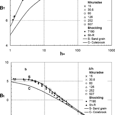
Moody’s chart
The Moody chart or Moody diagram is a graph in non-dimensional plot that relates the Darcy Weisbach friction factor (f), Reynolds number(Re) and Relative Roughness parameter(ϵ/d) for fully developed flows in a circular pipe.
It can be used to calculate the Head loss (hf)(hf) through pipes for a given flow rate or the flow rate through a pipe for a given head loss.
Head loss can be calculated using the Darcy Weisbach equation,

Where,
Density of the fluid
f Friction factor from the Moody chart
l Length of the pipe
V Average fluid velocity in the pipe
d Pipe diameter
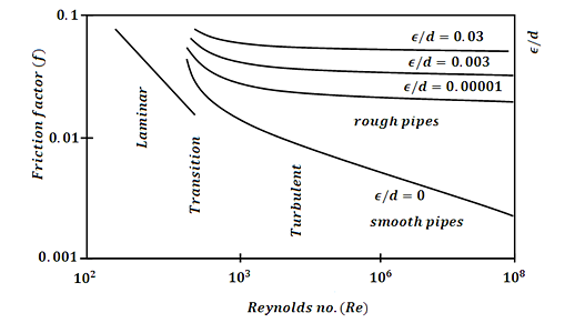
It may be visible from the discern that the graph includes three fluid go with the drift regimes: Laminar Flow (Re≤2300) Transition Flow (2300may be visible that the friction element for laminar go with the drift is a characteristic of Reynolds quantity by myself and is unbiased of relative roughness of the pipe. While the friction element for turbulent go with the drift is a characteristic of each Reynolds quantity and relative roughness of the pipe.
The friction element for transition go with the drift can normally be interpolated among the laminar price at Re = 2300 and the turbulent price at Re = 4000. The Relative Roughness parameter is the ratio of the imply top of roughness of the pipe to the pipe diameter (ϵ/d).
For hard pipes the fiction element will become unbiased of the Reynolds quantity and relies upon simplest at the relative roughness this occurs for the reason that thickness of the laminar sub layer reduces, absolutely exposing the floor roughness.
Darcy-Weisbach & Hazen- William’s equation for frictional head loss
Pressure Loss
The pressure loss (or major loss) in a pipe, tube or duct can be calculated with the Darcy-Weisbach equation
Δpmajor_loss = λ (l / dh) (ρf v2 / 2) (1)
Where
Δpmajor_loss = major (friction) pressure loss in fluid flow (Pa (N/m2), psf (lb/ft2))
λ = Darcy-Weisbach friction coefficient
l = length of duct or pipe (m, ft)
v = velocity of fluid (m/s, ft/s)
dh = hydraulic diameter (m, ft)
ρf = density of fluid (kg/m3, slugs/ft3)
Darcy-Weisbach Friction Loss Equation:

For square pipes (ducts), D=4A/P is called the hydraulic diameter. More statistics approximately hydraulic diameter may be discovered on our non-round to round pipe conversion page.
g = acceleration because of gravity = 32.174 ft/s2 = 9.806 m/s2.
The Hazen–Williams equation is an empirical dating which relates the go with the drift of water in a pipe with the bodily homes of the pipe and the stress drop due to friction. It is used with inside the layout of water pipe systems consisting of hearth place sprinkler systems, water deliver networks, and irrigation systems. It is known as after Allen Hazen and Gardner Stewart Williams.
The Hazen–Williams equation has the gain that the coefficient C isn't a characteristic of the Reynolds number, however it has the downside that it's miles most effective legitimate for water. Also, it does now no longer account for the temperature or viscosity of the water, and consequently is most effective legitimate at room temperature and traditional velocities.
Major loss (hf) is the strength (or head) loss (expressed in period units - consider it as strength in keeping with unit weight of fluid) because of friction among the shifting fluid and the duct. It is likewise called friction loss. The Darcy-Weisbach technique is normally taken into consideration greater correct than the Hazen-Williams technique. Additionally, the Darcy-Weisbach technique is legitimate for any liquid or gas; Hazen-Williams is handiest legitimate for water at regular temperatures (forty to seventy five oF).
Hazen-Williams is less difficult than Darcy-Weisbach for calculations in which you're fixing for flowrate, speed, or diameter. More Discussion and References. The Darcy-Weisbach calculation does now no longer test for unreasonable inputs along with poor values. All values need to be entered as positive.
Hydraulic gradient and energy gradient
In the pages at the float of a fluid via pipes, it's miles visible that there may be a lack of head. Whilst a number of that is because of the impact of unexpected contraction or expansions with inside the pipe diameter, pipe fittings including bends and valves and access and go out losses, a lack of capability head (i.e. The enter of the pipe is better than the outflow) a big element is because of the friction with inside the pipe (The Darcy Equation).
However in a pipe of uniform move section, there can be no lack of pace head and so the lack of Total Energy can be the end result of a loss in Pressure Head. Soil water capability is the using pressure at the back of water movement. The fundamental gain of the "capability" idea is that it presents a unified degree through which the water country may be evaluated at anytime and anywhere in the soil-plant-ecosystem continuum (Hillel, 1980).
Soil water is situation to some of forces. These forces encompass gravity, hydraulic pressure, the enchantment of the soil matrix for water, the presence of solutes, and the movement of outside fuelling pressure (Hillel, 1980). At any factor with inside the soil, general soil water capability is the sum of all the contributing forces.
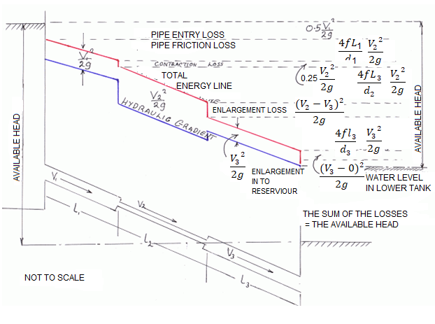
Energy Gradient:
The term 'Energy grade line (EGL) (electricity line, electricity gradient)' because it applies to the location of reclamation may be described as ' The line displaying the overall electricity at any factor in a pipe. The general electricity with inside the glide of the phase as regards to a datum line is the sum of the elevation of the pipe centerline, the piezometric height (or stress head), and the speed head.
The electricity grade line will slope (drop) with inside the course of glide besides in which electricity is introduced with the aid of using mechanical devices. The line representing the elevation of the overall head of glide is the electricity line. The slope of the road is called the electricity gradient. A line that represents the elevation of electricity head (in toes or meters) of water flowing in a pipe, conduit, or channel. The line is drawn above the hydraulic grade line (gradient) a distance identical to the speed head (V2/2g) of the water flowing at every phase or factor alongside the pipe or channel.
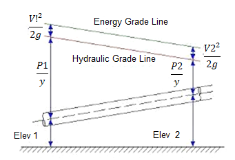
Pipes in series and parallel
Pipe in Series:
Pipes are said to be in series if they are connected end to end (in continuation with each other) so that the fluid flows in a continuous line without any branching. The volume rate of flow through the pipes in series is the same throughout.
Suppose a pipe line consists of a number of pipes of different sizes and lengths.

Fig. Pipe in series
Let d1, d2, d3 be the diameters of the component pipes.
Let l1, l2, l3 be the lengths of these component pipes.
Let v1, v2, v3 be the velocities in these pipes.
Pipes connected in continuation as in this case are said to be connected in series. In this arrangement the rate of discharge Q is the same in all the pipes. Ignoring secondary losses the total loss of head is equal to the sum of the friction losses in the individual pipes.
If hf1, hf2, hf3 be the losses of head in the individual pipes the total loss of head hf is given by,
hf = hf1 + hf2 + hf3 = 4fl1/d1 . v12/2g + 4fl2/d2 . v22/2g + 4fl3/d3 . v32/2g
= fl1Q2/3.0257 d15 + fl2Q2/3.0257 d25+ fl3Q2/3.0257 d35
If the pipe coefficient of the pipes are different the above equation can be re arranged as
Fl/d5 = f1l1/d15 + f2l2/d25 + f3l3/d35 + ……
Equivalent Pipe Corresponding to a Given Set of Pipes in Series:
Let d1, d2, d3 be the diameters, and l1, l2, l3 be the lengths of the various pipes in a series connection. Let Q be the discharge. Let hf be the total loss of head.
Let d be the diameter of an equivalent pipe of length l to replace the compound pipe to pass the same discharge at the same loss of head.
hf = fl1Q2/3.0257 d15 + fl2Q2/3.0257 d25+ fl3Q2/3.0257 d35 = flQ2/3.0257 d5
l/d5 = l1/d15+ l2/d25 + l3/d35
The above relation is called Dupuit’s equation.
Equivalent Length of a Pipe with Intermediate Fittings:
Suppose a pipe of length I is provided with an intermediate fitting due to which the loss of head = k(v2/2g). Let Ie be the length of pipe, the friction loss due to which is equal to k(v2/2g).
4fle/d . v2/2g = k v2/2g le = kd/4f
This length may be added to the actual length of the pipe to determine the overall loss of head. Similarly if le1, le2, le3 . . . Etc. are the equivalent lengths of pipe corresponding to various fittings.
overall loss of head = 4f 
Pipes Connected in Parallel:
Pipes are said to be in parallel when they are so connected that the flow from a pipe branches or divides into two or more separate pipes and then reunite into a single pipe.
Suppose a main pipe branched at section 1-1 into two pipes of lengths l1 and l2 and diameters d1 and d2 and unite again at a section 2-2 to form a single pipe.
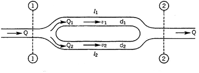
Then the two branch pipes are said to be connected in parallel.
In this arrangement the total discharge Q divides into components Q1 and Q2 along the branch pipes such that –
Q = Q1 + Q2
In this arrangement the loss of head from section 1-1 to section 2-2 is equal to the loss of head in any one of the branch pipes.
hf = hf1 = hf2


Hence the total discharge Q divides into components Q1 and Q2 satisfying the above equation.
Similarly when a number of pipes be connected in parallel, then also, the total loss of head in the system is equal to the loss of head in any one of the pipes.
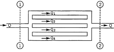
For example in the arrangement shown in Fig, the total loss of head in the system
= Loss of head from section
1 – 1 to section 2 – 2
hf = hf1 = hf2 = hf3 = hf4
The total discharge Q = Q1 + Q2 + Q3 + Q4

Branched pipes
Flow through branched pipes can be described because the fluid glide through a piping machine wherein 3 or greater than 3 reservoirs can be linked with every different with the assist of pipes and could have one or a couple of junctions. Now we are able to see right here one parent as displayed right here.
Three reservoirs are linked right here with the assist of piping machine and this piping machine and reservoirs are linked with one unmarried junction i.e. junction D. In numerous branched pipe glide problems, we are able to have a few specs of branched piping machine and generally we are able to need to decide the glide of fluid through every pipe. Let us anticipate that we've got data approximately the statistics for period of pipes, diameter of pipes and coefficient if friction for every pipe and we want to locate the statistics for glide of water through every pipe.
Principle and equations used for solving such problems
We will have to recall the following principles and we will have to use following equations for securing the desired data for such problems.
- Continuity equation
- Bernoulli’s equation
- Darcy-Weisbach equation
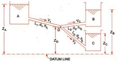
Let us consider that three reservoirs are A, B and C and piping system will have pipe 1, pipe 2 and pipe 3 and a single junction D as displayed above in figure.
Flow of water from reservoir A will take place to junction D and flow of water from junction D will be towards reservoir C.
Flow of water from junction D to reservoir B will only possible if piezometric head at D will be more than the piezometric head at B.
Let us consider the following terms from above figure.
ZA, ZB and ZC = Datum head at reservoir A, B and C respectively
V1, V2 and V3= Velocity of flow of water through pipe 1, 2 and 3 respectively
L1, L2 and L3 = length of pipe 1, 2 and 3 respectively
hf1, hf2 and hf3 = loss of head for pipe 1, 2 and 3 respectively
Let us now use the concept of Bernoulli’s equation for flow from A to D and we will have following equation as mentioned here.
ZA = ZD + PD/g + hf1
Let us now use the concept of Bernoulli’s equation for flow from D to B and we will have following equation as mentioned here.
ZD + PD/g = ZB + hf2
Let us now use the concept of Bernoulli’s equation for flow from D to C and we will have following equation as mentioned here.
ZD + PD/g = ZC + hf3
Now we will use the concept of continuity equation and we will have following equation as mentioned here.
Discharge through AD = Discharge through DB + Discharge through DC
Now as we can see that we are having with above four equations and we have to secure the value of V1, V2 and V3.
We will use above four equations to secure the value of flow of water through each pipe.
Further we will go ahead to find out the basic concept of power transmission through pipes, in the subject of fluid mechanics, with the help of our next post.
Siphon
There are main theories approximately how siphons motive liquid to glide uphill, towards gravity, without being pumped, and powered simplest with the aid of using gravity.
The conventional concept for hundreds of years became that gravity pulling the liquid down at the go out facet of the siphon ended in decreased strain on the pinnacle of the siphon. Then atmospheric strain became capable of push the liquid from the higher reservoir, up into the decreased strain on the pinnacle of the siphon, like in a barometer or ingesting straw, after which over. However, it's been verified that siphons can function in a vacuum and to heights exceeding the barometric top of the liquid.
Consequently, the concord anxiety concept of siphon operation has been advocated, wherein the liquid is pulled over the siphon in a manner much like the chain fountain. It want now no longer be one concept or the opposite this is accurate, however alternatively each theories can be accurate in unique occasions of ambient strain.
The atmospheric strain with gravity concept glaringly cannot give an explanation for siphons in vacuum, wherein there may be no giant atmospheric strain. But the concord anxiety with gravity concept cannot give an explanation for CO2 fuelling siphons, siphons operating no matter bubbles, and the flying droplet siphon, wherein gases do now no longer exert giant pulling forces, and beverages now no longer in touch cannot exert a cohesive anxiety force.
The chain version is a beneficial however now no longer absolutely correct conceptual version of a siphon. The chain version allows to apprehend how a siphon can purpose liquid to go with the drift uphill, powered most effective with the aid of using the downward pressure of gravity. A siphon can every now and then be concept of like a sequence striking over a pulley, with one stop of the chain piled on a better floor than the other. Since the duration of chain at the shorter aspect is lighter than the duration of chain at the taller aspect, the heavier chain at the taller aspect will pass down and pull up the chain at the lighter aspect.
Similar to a siphon, the chain version is glaringly simply powered with the aid of using gravity performing at the heavier aspect, and there's genuinely no violation of conservation of energy, due to the fact the chain is in the end simply shifting from a better to a decrease location, because the liquid does in a Even the falling lighter decrease leg from C to D can purpose the liquid of the heavier higher leg to go with the drift up and over into the decrease reservoir There are some of troubles with the chain version of a siphon, and information those variations allows to give an explanation for the real workings of siphons.
First, not like with inside the chain version of the siphon, it isn't always in reality the burden at the taller aspect in comparison to the shorter aspect that matters. Rather it's miles the distinction in peak from the reservoir surfaces to the pinnacle of the siphon, that determines the stability of pressure. For example, if the tube from the higher reservoir to the pinnacle of the siphon has a far large diameter than the taller segment of tube from the decrease reservoir to the pinnacle of the siphon, the shorter higher segment of the siphon might also additionally have a far large weight of liquid in it, and but the lighter extent of liquid with inside the down tube can pull liquid up the fatter up tube, and the siphon can feature
Transmission of power through pipes
Power is transmitted via pipes through flowing water or different drinks flowing via them. Power transmitted via pipes could be established over the subsequent elements as noted right here.
• Weight of the liquid flowing via the pipe
• Total head to be had on the give up of the pipe
Now we are able to don't forget a tank with which a pipe AB is connected. Let us don't forget the subsequent phrases from figure.
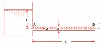
L = Length of the pipe
D = Diameter of the pipe
H = Total head available at the inlet of the pipe
V= Velocity of flow in pipe
hf = Loss of head due to friction
f = Co-efficient of friction
Power transmitted at the outlet of the pipe will be determined with the help of following formula as mentioned here.
P = g/1000 π/4. d2 V(H –  ) kW
) kW
Efficiency of power transmission
Efficiency of electricity transmission could be decided with the assist of following method as noted right here.


Condition for maximum transmission of power
Now we are able to locate right here the circumstance for max transmission of electricity and it may be secured through differentiating the equation of electricity transmitted at the hole of the pipe.


Above expression is the circumstance of most transmission of electricity. We can finish from above equation that electricity transmitted via a pipe could be most whilst the top loss because of friction could be one-0.33 of the full head at inlet.
Key Takeaways:
- The general electricity with inside the glide of the phase as regards to a datum line is the sum of the elevation of the pipe centerline, the piezometric height (or stress head), and the speed head.
- We will have to recall the following principles and we will have to use following equations for securing the desired data for such problems.
- There are main theories approximately how siphons motive liquid to glide uphill, towards gravity, without being pumped, and powered simplest with the aid of using gravity.
Hardy-Cross method of pipe networks
The technique became first posted in November 1936 via way of means of its namesake, Hardy Cross, a structural engineering professor on the University of Illinois at Urbana–Champaign. The Hardy Cross technique is an version of the Moment distribution technique, which became additionally advanced via way of means of Hardy Cross as a manner to decide the forces in statically indeterminate structures.
The advent of the Hardy Cross technique for reading pipe float networks revolutionized municipal water deliver design. Before the technique became introduced, fixing complicated pipe structures for distribution became extraordinarily tough because of the nonlinear courting among head loss and float. The technique became later made out of date via way of means of laptop fixing algorithms using the Newton–Raphson technique or different numerical strategies that get rid of the want to remedy nonlinear structures of equations via way of means of hand. The Hardy Cross technique is an utility of continuity of float and continuity of capacity to iteratively remedy for flows in a pipe community
In the case of pipe float, conservation of float method that the float in is same to the float out at every junction with inside the pipe. Conservation of capacity method that the whole directional head loss alongside any loop with inside the gadget is zero (assuming that a head loss counted towards the float is truly a head gain). Hardy Cross advanced strategies for fixing float networks. Each technique begins off evolved via way of means of preserving both continuity of float or capacity, after which iteratively solves for the different.
Piping networks have pretty a extensive variety of sensible applications, from water and fuel line distribution structures to aircon installations. Although easy issues, together with for instance, a unmarried department connecting reservoirs, can be solved analytically, greater complicated community issues want an iterative approach, ordinary to a virtual computer.
The maximum famous approach for fixing this sort of issues is the Hardy-Cross approach. Also, the pipe length, diameter, roughness and different key traits ought to be known. Before the approach became introduced, fixing complicated pipe structures for distribution became extraordinarily hard because of the nonlinear courting among head loss and glide.
Water distribution gadget fashions have grow to be very essential and sensible device for civil engineers. Models are frequently used to optimize the layout of latest distribution structures or examine fundamental extensions or changes to present distribution structures. The advent of the Hardy Cross approach for studying pipe glide networks revolutionized municipal water deliver layout (Pdhengineer.com, 2014). The Hardy Cross approach is commonly used because the pipe community evaluation with the aid of using maximum engineers.
The Hardy-Cross analysis is based on the principles that
- At each junction, the total inflow must be equal to total outflow.

2. Head balance criterion: algebraic sum of the head losses around any closed-loop is zero.

For a given pipe system, with known junction outflows, the Hardy-Cross method is an iterative procedure based on initially estimated flows in pipes. Estimated pipe flows are corrected with iteration until head losses in the clockwise direction and in the anticlockwise direction are equal within each loop.
- A trial distribution is made arbitrarily but in such a way that continuity equation is satisfied at each junction.
2. With the assumed value of Q, the head loss in each pipe is calculated according to the equation
hf = r Qn
Where
hf : head loss
r : head loss per unit flow
n : flow exponent
3. The net head loss around each loop is calculated.
4. If the net head loss due to assumed values of Q round the loop is zero, then the assumed values of Q in that loop are correct. If this is not the case, then the assumed values of Q are corrected by including a correction ï„Q for the flows till the circuit is balanced.
5. The correction factor ï„Q is obtained by

6. For turbulent flow, the value of n=2 and hence the correction factor becomes

7. If the value of ï„Q is positive, then it is added to the flow in the clockwise direction and subtracted from the flows in the anticlockwise direction.
8. After the correction have been applied to each pipe in a loop and to all loops, a second trial calculation is made for all loops. This procedure is repeated till ï„Q becomes negligible.
Water-hammer
Water hammer is a phenomenon which can arise in any piping gadget wherein valves are used to manipulate the float of beverages or steam. Water hammer is the end result of a stress surge, or high-stress shockwave that propagates via a piping gadget whilst a fluid in movement is pressured to extrude route or prevent abruptly.
This shockwave is likewise generally called a hydraulic surprise or hydraulic surge, and can be characterized through a marked banging or knocking sound at the pipes right now after shutoff. Water hammer can arise whilst an open valve unexpectedly closes, inflicting the water to slam into it, or whilst a pump unexpectedly shuts down and the float reverses route lower back to the pump. Since water is incompressible, the effect of the water consequences in a surprise wave that propagates at the velocity of sound among the valve and the following elbow with inside the piping gadget or in the column of water after the pump.
These unexpected stoppages of float and the ensuing will increase in stress from the surprise waves can motive full-size harm to the general piping gadget both because of a unique occasion or be cumulative harm happening over time. Ignoring water hammer can in the long run bring about the catastrophic failure of your float gadget.
The long-time period consequences of water hammer can include: Pump and Flow System Damage Repeated water hammer may motive full-size harm to pumps, present valves, and instruments, result in the catastrophic failure of casketed joints and growth joints, and have an effect on the integrity of pipe partitions and welded joints.
Pressure head due to sudden closure of valve.
The pressure rise due to water hammer depends upon
- The velocity of the flow in the water pipe
- The length of pipe
- Time to taken close the valve
- Elastic properties of the material of the pipe
In the following cases water hammer is been considered
- Gradual closure of the valve
- Sudden closure of valve when the pipe is rigid,
- Sudden closure of valve when the pipe is elastic
The time required for the pressure wave to travel from the valve to the reservoir and back to the valve is:
t = 2L/C
Where :
L = Length of the pipe (m), C = Speed of pressure wave (m/s)
If the valve time of closure is tc, then
- If tc > 2L/C the closure is considered gradual.
- If tc ≤ 2L/C the closure is considered Sudden.
When the water flowing in a protracted pipe line is all at once delivered to relaxation through the closure of a valve on the decrease give up or through any comparable cause, a surprising upward push in strain will arise because of the destruction of the momentum of the transferring frame of water. This will result in a strain wave or a surprise wave that's transmitted alongside the pipe. The speed of this strain wave is identical to speed of sound in water. The strain wave and the related pulsations or fluctuations in strain produce noise referred to as knocking or water hammer.
Such surprising strain rises have a knocking or hammering impact at the pipe wall. Pen shares of hydro-electric powered plants, water mains etc. are subjected to water hammer consequences because of surprising valve closures on the decrease ends. Such surprising strain rises produce sizeable hoop stresses with inside the pipe partitions and might from time to time result in pipe burst. Hence valves, on the decrease ends of such pipes need to be closed gradually.
The strain upward push produced because of surprising closure of valve relies upon on the rate of water with inside the pipe, the duration of the pipe, the c programming language of time taken to shut the valve and the pliability or stress of the pipe material. At the graduation of degree 1, the valve is closed and the layer of water near the valve is delivered to relaxation. This layer of water is compressed and therefore the strain will upward push through h and the pipe wall gets stretched. Successive layers are delivered to relaxation in succession and the strain rises for extra duration of pipe.
The hatched element represents water at relaxation. At the opposite give up of the pipe, is the reservoir R. Now the excessive strain wave actions with inside the upstream direction (i.e., in the direction of the reservoir) with a speed c, bringing the layers of water to relaxation, with inside the path of its passage.
Key takeaways:
- The Hardy Cross technique is a utility of continuity of float and continuity of capacity to iteratively remedy for flows in a pipe community
- The Hardy Cross approach is commonly used because the pipe community evaluation with the aid of using maximum engineers.
References:
1. Hydraulics & Fluid Mechanics- Dr.Modi& Dr. Seth
2. Fluid Mechanics-Streeter & Wylie
3. Fluid Mechanics- Dr. A.K.Jain
4. Fluid Mechanics through problems- Garde
5. Theory and applications of Fluid Mechanics- K. Subramanya
6. Foundation of Fluid Mechanics-Yuan
Unit - 2
Flow Through Pipes
Hydraulically smooth and rough pipes
• When the common intensity okay of the floor irregularities is much less than laminar sub-layer of the floor δ is known as hydrodynamic best friend easy boundary.
• The eddy which shaped out of doors of the laminar sub-layer attempt to penetrate with inside the laminar sub-layer boundary is known as as easy boundary as proven in
• When the common intensity okay of the floor irregularities is more than laminar sub-layer of floor δ is known as hydrodynamic best friend tough boundary.
• The eddy which shaped out of doors of the laminar sub layer penetrates into the laminar sub-layer.
Such boundary is known as as tough boundary as proven in. By Nikuradse’s experiments, (1) When okay / δ < 0>6 , tough boundary. (3) When 0.25 < k> 100, tough boundary. (3) u.okay / v lies among four to 100, transition boundary.
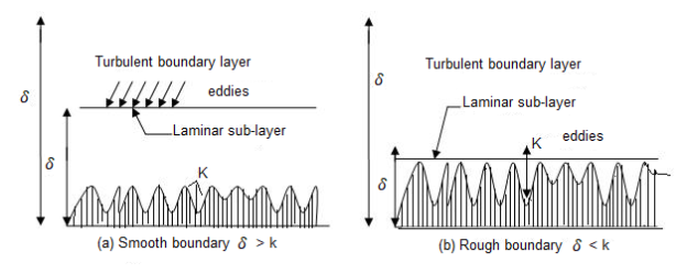
(a) Smooth Boundary input picture description here (b) Rough Boundary Let the common top of the irregularities projecting from the floor of boundary be denoted as ‘K’. Now, if the fee of ‘K’ is big for a boundary then the boundary is known as as Rough boundary.
This is the type of difficult and easy limitations primarily based totally on boundary traits. But for correct type waft and fluid traits also are considered. Hydro-dynamically easy boundary
1) For a turbulent waft analysis, the waft is split into elements or portions.
2) The first component includes a skinny layer of fluid with inside the on the spot neighborhood of the boundary, wherein the viscous shear strain is more potent while the shear strain because of turbulent is negligible. This is called laminar sub layer.
3) The 2d part of waft is the only wherein shear strain because of turbulence is better or big compared to the viscous shear and this region is known as as Turbulent region.
4) The region up to which or the peak up to which the impact of viscosity predominates is denoted through δ′.
5) So, we are able to say that if the common pace top ‘K’ is much less than ‘δ′’, then the boundary is known as Smooth boundary.
6) This occurs because, out of doors the laminar sub-layer the waft is turbulent and eddies of diverse sizes gift with inside the turbulent waft try and penetrate through the laminar sub-layer, however because of the top notch thickness of laminar sub-layer the eddies are not able to attain the floor irregularities and so the boundary behaves as easy boundary.
Hydro-dynamically difficult boundary
1) If the Reynolds range of the waft increases, the thickness of laminar sub-layer decreases.
2) If this occurs, then the common top ‘K’ of irregularities is above the laminar sub-layer and as a consequence the eddies gift will are available in touch with irregularities of the floor and lot of electricity might be lost.
3) Such a boundary is called Hydro-dynamically difficult boundary.
Frictional resistance to flow of fluid in smooth and rough pipes
The time period friction loss (or frictional loss) has some of unique meanings, relying on its context. In fluid go with the drift it's miles the top loss that takes place in a containment which includes a pipe or duct because of the impact of the fluid's viscosity close to the floor of the containment. In mechanical structures which includes inner combustion engines, the time period refers back to the strength misplaced in overcoming the friction among shifting surfaces. In economics, frictional loss is herbal and irrecoverable loss in a transaction or the cost(s) of doing enterprise too small to account for.
Contrast with treat in shipping, which made a widespread allowance for in any other case unaccounted for factors. Friction loss is a large engineering situation anywhere fluids are made to go with the drift, whether or not absolutely enclosed in a pipe or duct, or with a floor open to the air. Historically, it's miles a situation in aqueducts of all kinds, at some stage in human history. It is likewise applicable to sewer lines. Systematic have a look at strains lower back to Henry Darcy, an aqueduct engineer. Natural flows in river beds are essential to human activity; friction loss in a movement mattress has an impact on the peak of the go with the drift, specifically large at some point of flooding. The economies of pipelines for petrochemical transport are fantastically suffering from friction loss.
The Yamal–Europe pipeline consists of methane at a extent go with the drift charge of 32.3 × 10⁹ m3 of fuelling according to year, at Reynolds numbers more than 50 × 106 In hydropower applications, the power misplaced to pores and skin friction in flume and penstock isn't always to be had for beneficial work, say producing electricity. In refrigeration applications, power is expended pumping the coolant fluid through pipes or through the condenser. In cut up structures, the pipes wearing the coolant take the area of the air ducts in HVAC structures.
The loss of head, due to friction in pipes is given by,

In this equation, the value of coefficient of friction (f), should be known accurately for predicting the loss of head due to friction in pipes.
On the basis of dimensional analysis, it can be shown that the pressure loss in a straight pipe of diameter (D), length (L), roughness (K), average velocity (V¯), viscosity (‘μ’) and density of fluid (‘ρ’) is


Experimentally it was found that pressure drop is a function of L/D to the first power.


Key Takeaways:
- The eddy which shaped out of doors of the laminar sub layer penetrates into the laminar sub-layer.
- In economics, frictional loss is herbal and irrecoverable loss in a transaction or the cost(s) of doing enterprise too small to account for.
Nikuradze’s paintings achieved circa 1940 remains the gold general for the impact of roughness at the inner of a pipe. He used water and sand roughened pipes. He labeled round debris into slim particle length levels and fixed them onto the inner of diverse pipes of various diameters.
He then flowed water via the pipes at various waft fees and measured the strain differential throughout the ends of the pipe. By various the inner diameter of the pipes he became capable of create a vast variety of Reynolds variety waft. His effects have been exquisite for the roughened pipes however he additionally made a big mistake via way of means of seeking to healthy easy walled waft and roughened wall waft. This mistake nevertheless permeates the presently general idea of fluid dynamics inflicting a actual mess.
Johann Nikuradse (November 20, 1894 – July 18, 1979) became a Georgia-born German engineer and physicist. His brother, Alexander Nikuradse, became additionally a Germany-primarily based totally physicist and geopolitician recognized for his ties with Alfred Rosenberg and for his function in saving many Georgians at some stage in World War II.
He became born in Samtredia, Georgia (then a part of the Kutais Governorate, Imperial Russia) and studied at Kutaisi. In 1919, via the guidelines of the conspicuous Georgian student Petre Melikishvili, he went overseas for similarly studies. The 1921 Sovietization of Georgia precluded his go back to place of birth and Nikuradse naturalized as a German citizen.
He succeeded in placing himself in Prandtl's favour and as a consequence superior to the location of branch head. In spite of his near ties with the Nazi Party, Nikuradse came, withinside the early 1930s, beneathneath hearthplace of the institute's National Socialist Factory Cell Organization whose individuals accused him of spying for the Soviet Union and of stealing books from the institute. Prandtl to begin with defended Nikuradse, however became in the end pressured to brush aside him in 1934.
He then served as a professor on the University of Breslau (1934–1945), and an honorary professor on the Aachen Technical University due to the fact 1945. Nikuradse lived ordinarily in Göttingen and engaged in hydrodynamics. His quality recognized test became posted in Germany in 1933. Nikuradse cautiously measured the friction that a turbulent fluid reviews because it flows via a hard pipe. He used grains of sand with various roughnesses and observed that, the rougher the floor the extra the friction, and therefore a extra strain loss.
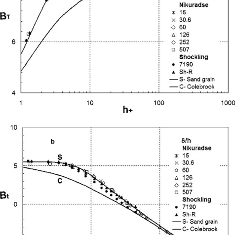
Moody’s chart
The Moody chart or Moody diagram is a graph in non-dimensional plot that relates the Darcy Weisbach friction factor (f), Reynolds number(Re) and Relative Roughness parameter(ϵ/d) for fully developed flows in a circular pipe.
It can be used to calculate the Head loss (hf)(hf) through pipes for a given flow rate or the flow rate through a pipe for a given head loss.
Head loss can be calculated using the Darcy Weisbach equation,

Where,
Density of the fluid
f Friction factor from the Moody chart
l Length of the pipe
V Average fluid velocity in the pipe
d Pipe diameter
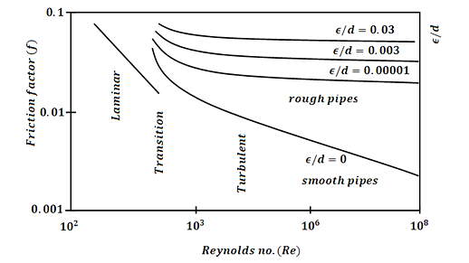
It may be visible from the discern that the graph includes three fluid go with the drift regimes: Laminar Flow (Re≤2300) Transition Flow (2300may be visible that the friction element for laminar go with the drift is a characteristic of Reynolds quantity by myself and is unbiased of relative roughness of the pipe. While the friction element for turbulent go with the drift is a characteristic of each Reynolds quantity and relative roughness of the pipe.
The friction element for transition go with the drift can normally be interpolated among the laminar price at Re = 2300 and the turbulent price at Re = 4000. The Relative Roughness parameter is the ratio of the imply top of roughness of the pipe to the pipe diameter (ϵ/d).
For hard pipes the fiction element will become unbiased of the Reynolds quantity and relies upon simplest at the relative roughness this occurs for the reason that thickness of the laminar sub layer reduces, absolutely exposing the floor roughness.
Darcy-Weisbach & Hazen- William’s equation for frictional head loss
Pressure Loss
The pressure loss (or major loss) in a pipe, tube or duct can be calculated with the Darcy-Weisbach equation
Δpmajor_loss = λ (l / dh) (ρf v2 / 2) (1)
Where
Δpmajor_loss = major (friction) pressure loss in fluid flow (Pa (N/m2), psf (lb/ft2))
λ = Darcy-Weisbach friction coefficient
l = length of duct or pipe (m, ft)
v = velocity of fluid (m/s, ft/s)
dh = hydraulic diameter (m, ft)
ρf = density of fluid (kg/m3, slugs/ft3)
Darcy-Weisbach Friction Loss Equation:

For square pipes (ducts), D=4A/P is called the hydraulic diameter. More statistics approximately hydraulic diameter may be discovered on our non-round to round pipe conversion page.
g = acceleration because of gravity = 32.174 ft/s2 = 9.806 m/s2.
The Hazen–Williams equation is an empirical dating which relates the go with the drift of water in a pipe with the bodily homes of the pipe and the stress drop due to friction. It is used with inside the layout of water pipe systems consisting of hearth place sprinkler systems, water deliver networks, and irrigation systems. It is known as after Allen Hazen and Gardner Stewart Williams.
The Hazen–Williams equation has the gain that the coefficient C isn't a characteristic of the Reynolds number, however it has the downside that it's miles most effective legitimate for water. Also, it does now no longer account for the temperature or viscosity of the water, and consequently is most effective legitimate at room temperature and traditional velocities.
Major loss (hf) is the strength (or head) loss (expressed in period units - consider it as strength in keeping with unit weight of fluid) because of friction among the shifting fluid and the duct. It is likewise called friction loss. The Darcy-Weisbach technique is normally taken into consideration greater correct than the Hazen-Williams technique. Additionally, the Darcy-Weisbach technique is legitimate for any liquid or gas; Hazen-Williams is handiest legitimate for water at regular temperatures (forty to seventy five oF).
Hazen-Williams is less difficult than Darcy-Weisbach for calculations in which you're fixing for flowrate, speed, or diameter. More Discussion and References. The Darcy-Weisbach calculation does now no longer test for unreasonable inputs along with poor values. All values need to be entered as positive.
Hydraulic gradient and energy gradient
In the pages at the float of a fluid via pipes, it's miles visible that there may be a lack of head. Whilst a number of that is because of the impact of unexpected contraction or expansions with inside the pipe diameter, pipe fittings including bends and valves and access and go out losses, a lack of capability head (i.e. The enter of the pipe is better than the outflow) a big element is because of the friction with inside the pipe (The Darcy Equation).
However in a pipe of uniform move section, there can be no lack of pace head and so the lack of Total Energy can be the end result of a loss in Pressure Head. Soil water capability is the using pressure at the back of water movement. The fundamental gain of the "capability" idea is that it presents a unified degree through which the water country may be evaluated at anytime and anywhere in the soil-plant-ecosystem continuum (Hillel, 1980).
Soil water is situation to some of forces. These forces encompass gravity, hydraulic pressure, the enchantment of the soil matrix for water, the presence of solutes, and the movement of outside fuelling pressure (Hillel, 1980). At any factor with inside the soil, general soil water capability is the sum of all the contributing forces.
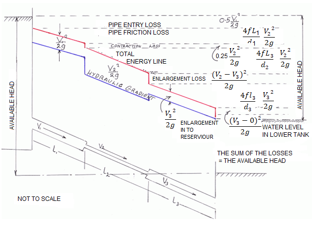
Energy Gradient:
The term 'Energy grade line (EGL) (electricity line, electricity gradient)' because it applies to the location of reclamation may be described as ' The line displaying the overall electricity at any factor in a pipe. The general electricity with inside the glide of the phase as regards to a datum line is the sum of the elevation of the pipe centerline, the piezometric height (or stress head), and the speed head.
The electricity grade line will slope (drop) with inside the course of glide besides in which electricity is introduced with the aid of using mechanical devices. The line representing the elevation of the overall head of glide is the electricity line. The slope of the road is called the electricity gradient. A line that represents the elevation of electricity head (in toes or meters) of water flowing in a pipe, conduit, or channel. The line is drawn above the hydraulic grade line (gradient) a distance identical to the speed head (V2/2g) of the water flowing at every phase or factor alongside the pipe or channel.
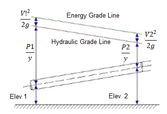
Pipes in series and parallel
Pipe in Series:
Pipes are said to be in series if they are connected end to end (in continuation with each other) so that the fluid flows in a continuous line without any branching. The volume rate of flow through the pipes in series is the same throughout.
Suppose a pipe line consists of a number of pipes of different sizes and lengths.

Fig. Pipe in series
Let d1, d2, d3 be the diameters of the component pipes.
Let l1, l2, l3 be the lengths of these component pipes.
Let v1, v2, v3 be the velocities in these pipes.
Pipes connected in continuation as in this case are said to be connected in series. In this arrangement the rate of discharge Q is the same in all the pipes. Ignoring secondary losses the total loss of head is equal to the sum of the friction losses in the individual pipes.
If hf1, hf2, hf3 be the losses of head in the individual pipes the total loss of head hf is given by,
hf = hf1 + hf2 + hf3 = 4fl1/d1 . v12/2g + 4fl2/d2 . v22/2g + 4fl3/d3 . v32/2g
= fl1Q2/3.0257 d15 + fl2Q2/3.0257 d25+ fl3Q2/3.0257 d35
If the pipe coefficient of the pipes are different the above equation can be re arranged as
Fl/d5 = f1l1/d15 + f2l2/d25 + f3l3/d35 + ……
Equivalent Pipe Corresponding to a Given Set of Pipes in Series:
Let d1, d2, d3 be the diameters, and l1, l2, l3 be the lengths of the various pipes in a series connection. Let Q be the discharge. Let hf be the total loss of head.
Let d be the diameter of an equivalent pipe of length l to replace the compound pipe to pass the same discharge at the same loss of head.
hf = fl1Q2/3.0257 d15 + fl2Q2/3.0257 d25+ fl3Q2/3.0257 d35 = flQ2/3.0257 d5
l/d5 = l1/d15+ l2/d25 + l3/d35
The above relation is called Dupuit’s equation.
Equivalent Length of a Pipe with Intermediate Fittings:
Suppose a pipe of length I is provided with an intermediate fitting due to which the loss of head = k(v2/2g). Let Ie be the length of pipe, the friction loss due to which is equal to k(v2/2g).
4fle/d . v2/2g = k v2/2g le = kd/4f
This length may be added to the actual length of the pipe to determine the overall loss of head. Similarly if le1, le2, le3 . . . Etc. are the equivalent lengths of pipe corresponding to various fittings.
overall loss of head = 4f 
Pipes Connected in Parallel:
Pipes are said to be in parallel when they are so connected that the flow from a pipe branches or divides into two or more separate pipes and then reunite into a single pipe.
Suppose a main pipe branched at section 1-1 into two pipes of lengths l1 and l2 and diameters d1 and d2 and unite again at a section 2-2 to form a single pipe.
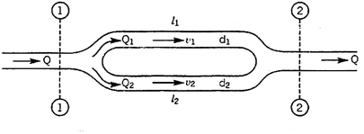
Then the two branch pipes are said to be connected in parallel.
In this arrangement the total discharge Q divides into components Q1 and Q2 along the branch pipes such that –
Q = Q1 + Q2
In this arrangement the loss of head from section 1-1 to section 2-2 is equal to the loss of head in any one of the branch pipes.
hf = hf1 = hf2


Hence the total discharge Q divides into components Q1 and Q2 satisfying the above equation.
Similarly when a number of pipes be connected in parallel, then also, the total loss of head in the system is equal to the loss of head in any one of the pipes.
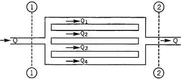
For example in the arrangement shown in Fig, the total loss of head in the system
= Loss of head from section
1 – 1 to section 2 – 2
hf = hf1 = hf2 = hf3 = hf4
The total discharge Q = Q1 + Q2 + Q3 + Q4

Branched pipes
Flow through branched pipes can be described because the fluid glide through a piping machine wherein 3 or greater than 3 reservoirs can be linked with every different with the assist of pipes and could have one or a couple of junctions. Now we are able to see right here one parent as displayed right here.
Three reservoirs are linked right here with the assist of piping machine and this piping machine and reservoirs are linked with one unmarried junction i.e. junction D. In numerous branched pipe glide problems, we are able to have a few specs of branched piping machine and generally we are able to need to decide the glide of fluid through every pipe. Let us anticipate that we've got data approximately the statistics for period of pipes, diameter of pipes and coefficient if friction for every pipe and we want to locate the statistics for glide of water through every pipe.
Principle and equations used for solving such problems
We will have to recall the following principles and we will have to use following equations for securing the desired data for such problems.
- Continuity equation
- Bernoulli’s equation
- Darcy-Weisbach equation
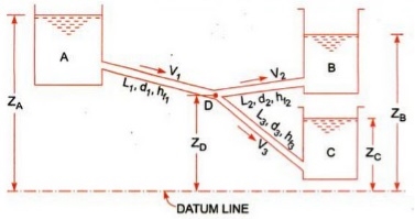
Let us consider that three reservoirs are A, B and C and piping system will have pipe 1, pipe 2 and pipe 3 and a single junction D as displayed above in figure.
Flow of water from reservoir A will take place to junction D and flow of water from junction D will be towards reservoir C.
Flow of water from junction D to reservoir B will only possible if piezometric head at D will be more than the piezometric head at B.
Let us consider the following terms from above figure.
ZA, ZB and ZC = Datum head at reservoir A, B and C respectively
V1, V2 and V3= Velocity of flow of water through pipe 1, 2 and 3 respectively
L1, L2 and L3 = length of pipe 1, 2 and 3 respectively
hf1, hf2 and hf3 = loss of head for pipe 1, 2 and 3 respectively
Let us now use the concept of Bernoulli’s equation for flow from A to D and we will have following equation as mentioned here.
ZA = ZD + PD/g + hf1
Let us now use the concept of Bernoulli’s equation for flow from D to B and we will have following equation as mentioned here.
ZD + PD/g = ZB + hf2
Let us now use the concept of Bernoulli’s equation for flow from D to C and we will have following equation as mentioned here.
ZD + PD/g = ZC + hf3
Now we will use the concept of continuity equation and we will have following equation as mentioned here.
Discharge through AD = Discharge through DB + Discharge through DC
Now as we can see that we are having with above four equations and we have to secure the value of V1, V2 and V3.
We will use above four equations to secure the value of flow of water through each pipe.
Further we will go ahead to find out the basic concept of power transmission through pipes, in the subject of fluid mechanics, with the help of our next post.
Siphon
There are main theories approximately how siphons motive liquid to glide uphill, towards gravity, without being pumped, and powered simplest with the aid of using gravity.
The conventional concept for hundreds of years became that gravity pulling the liquid down at the go out facet of the siphon ended in decreased strain on the pinnacle of the siphon. Then atmospheric strain became capable of push the liquid from the higher reservoir, up into the decreased strain on the pinnacle of the siphon, like in a barometer or ingesting straw, after which over. However, it's been verified that siphons can function in a vacuum and to heights exceeding the barometric top of the liquid.
Consequently, the concord anxiety concept of siphon operation has been advocated, wherein the liquid is pulled over the siphon in a manner much like the chain fountain. It want now no longer be one concept or the opposite this is accurate, however alternatively each theories can be accurate in unique occasions of ambient strain.
The atmospheric strain with gravity concept glaringly cannot give an explanation for siphons in vacuum, wherein there may be no giant atmospheric strain. But the concord anxiety with gravity concept cannot give an explanation for CO2 fuelling siphons, siphons operating no matter bubbles, and the flying droplet siphon, wherein gases do now no longer exert giant pulling forces, and beverages now no longer in touch cannot exert a cohesive anxiety force.
The chain version is a beneficial however now no longer absolutely correct conceptual version of a siphon. The chain version allows to apprehend how a siphon can purpose liquid to go with the drift uphill, powered most effective with the aid of using the downward pressure of gravity. A siphon can every now and then be concept of like a sequence striking over a pulley, with one stop of the chain piled on a better floor than the other. Since the duration of chain at the shorter aspect is lighter than the duration of chain at the taller aspect, the heavier chain at the taller aspect will pass down and pull up the chain at the lighter aspect.
Similar to a siphon, the chain version is glaringly simply powered with the aid of using gravity performing at the heavier aspect, and there's genuinely no violation of conservation of energy, due to the fact the chain is in the end simply shifting from a better to a decrease location, because the liquid does in a Even the falling lighter decrease leg from C to D can purpose the liquid of the heavier higher leg to go with the drift up and over into the decrease reservoir There are some of troubles with the chain version of a siphon, and information those variations allows to give an explanation for the real workings of siphons.
First, not like with inside the chain version of the siphon, it isn't always in reality the burden at the taller aspect in comparison to the shorter aspect that matters. Rather it's miles the distinction in peak from the reservoir surfaces to the pinnacle of the siphon, that determines the stability of pressure. For example, if the tube from the higher reservoir to the pinnacle of the siphon has a far large diameter than the taller segment of tube from the decrease reservoir to the pinnacle of the siphon, the shorter higher segment of the siphon might also additionally have a far large weight of liquid in it, and but the lighter extent of liquid with inside the down tube can pull liquid up the fatter up tube, and the siphon can feature
Transmission of power through pipes
Power is transmitted via pipes through flowing water or different drinks flowing via them. Power transmitted via pipes could be established over the subsequent elements as noted right here.
• Weight of the liquid flowing via the pipe
• Total head to be had on the give up of the pipe
Now we are able to don't forget a tank with which a pipe AB is connected. Let us don't forget the subsequent phrases from figure.
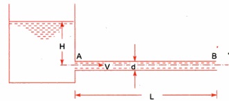
L = Length of the pipe
D = Diameter of the pipe
H = Total head available at the inlet of the pipe
V= Velocity of flow in pipe
hf = Loss of head due to friction
f = Co-efficient of friction
Power transmitted at the outlet of the pipe will be determined with the help of following formula as mentioned here.
P = g/1000 π/4. d2 V(H –  ) kW
) kW
Efficiency of power transmission
Efficiency of electricity transmission could be decided with the assist of following method as noted right here.


Condition for maximum transmission of power
Now we are able to locate right here the circumstance for max transmission of electricity and it may be secured through differentiating the equation of electricity transmitted at the hole of the pipe.


Above expression is the circumstance of most transmission of electricity. We can finish from above equation that electricity transmitted via a pipe could be most whilst the top loss because of friction could be one-0.33 of the full head at inlet.
Key Takeaways:
- The general electricity with inside the glide of the phase as regards to a datum line is the sum of the elevation of the pipe centerline, the piezometric height (or stress head), and the speed head.
- We will have to recall the following principles and we will have to use following equations for securing the desired data for such problems.
- There are main theories approximately how siphons motive liquid to glide uphill, towards gravity, without being pumped, and powered simplest with the aid of using gravity.
Hardy-Cross method of pipe networks
The technique became first posted in November 1936 via way of means of its namesake, Hardy Cross, a structural engineering professor on the University of Illinois at Urbana–Champaign. The Hardy Cross technique is an version of the Moment distribution technique, which became additionally advanced via way of means of Hardy Cross as a manner to decide the forces in statically indeterminate structures.
The advent of the Hardy Cross technique for reading pipe float networks revolutionized municipal water deliver design. Before the technique became introduced, fixing complicated pipe structures for distribution became extraordinarily tough because of the nonlinear courting among head loss and float. The technique became later made out of date via way of means of laptop fixing algorithms using the Newton–Raphson technique or different numerical strategies that get rid of the want to remedy nonlinear structures of equations via way of means of hand. The Hardy Cross technique is an utility of continuity of float and continuity of capacity to iteratively remedy for flows in a pipe community
In the case of pipe float, conservation of float method that the float in is same to the float out at every junction with inside the pipe. Conservation of capacity method that the whole directional head loss alongside any loop with inside the gadget is zero (assuming that a head loss counted towards the float is truly a head gain). Hardy Cross advanced strategies for fixing float networks. Each technique begins off evolved via way of means of preserving both continuity of float or capacity, after which iteratively solves for the different.
Piping networks have pretty a extensive variety of sensible applications, from water and fuel line distribution structures to aircon installations. Although easy issues, together with for instance, a unmarried department connecting reservoirs, can be solved analytically, greater complicated community issues want an iterative approach, ordinary to a virtual computer.
The maximum famous approach for fixing this sort of issues is the Hardy-Cross approach. Also, the pipe length, diameter, roughness and different key traits ought to be known. Before the approach became introduced, fixing complicated pipe structures for distribution became extraordinarily hard because of the nonlinear courting among head loss and glide.
Water distribution gadget fashions have grow to be very essential and sensible device for civil engineers. Models are frequently used to optimize the layout of latest distribution structures or examine fundamental extensions or changes to present distribution structures. The advent of the Hardy Cross approach for studying pipe glide networks revolutionized municipal water deliver layout (Pdhengineer.com, 2014). The Hardy Cross approach is commonly used because the pipe community evaluation with the aid of using maximum engineers.
The Hardy-Cross analysis is based on the principles that
- At each junction, the total inflow must be equal to total outflow.

2. Head balance criterion: algebraic sum of the head losses around any closed-loop is zero.

For a given pipe system, with known junction outflows, the Hardy-Cross method is an iterative procedure based on initially estimated flows in pipes. Estimated pipe flows are corrected with iteration until head losses in the clockwise direction and in the anticlockwise direction are equal within each loop.
- A trial distribution is made arbitrarily but in such a way that continuity equation is satisfied at each junction.
2. With the assumed value of Q, the head loss in each pipe is calculated according to the equation
hf = r Qn
Where
hf : head loss
r : head loss per unit flow
n : flow exponent
3. The net head loss around each loop is calculated.
4. If the net head loss due to assumed values of Q round the loop is zero, then the assumed values of Q in that loop are correct. If this is not the case, then the assumed values of Q are corrected by including a correction ï„Q for the flows till the circuit is balanced.
5. The correction factor ï„Q is obtained by

6. For turbulent flow, the value of n=2 and hence the correction factor becomes

7. If the value of ï„Q is positive, then it is added to the flow in the clockwise direction and subtracted from the flows in the anticlockwise direction.
8. After the correction have been applied to each pipe in a loop and to all loops, a second trial calculation is made for all loops. This procedure is repeated till ï„Q becomes negligible.
Water-hammer
Water hammer is a phenomenon which can arise in any piping gadget wherein valves are used to manipulate the float of beverages or steam. Water hammer is the end result of a stress surge, or high-stress shockwave that propagates via a piping gadget whilst a fluid in movement is pressured to extrude route or prevent abruptly.
This shockwave is likewise generally called a hydraulic surprise or hydraulic surge, and can be characterized through a marked banging or knocking sound at the pipes right now after shutoff. Water hammer can arise whilst an open valve unexpectedly closes, inflicting the water to slam into it, or whilst a pump unexpectedly shuts down and the float reverses route lower back to the pump. Since water is incompressible, the effect of the water consequences in a surprise wave that propagates at the velocity of sound among the valve and the following elbow with inside the piping gadget or in the column of water after the pump.
These unexpected stoppages of float and the ensuing will increase in stress from the surprise waves can motive full-size harm to the general piping gadget both because of a unique occasion or be cumulative harm happening over time. Ignoring water hammer can in the long run bring about the catastrophic failure of your float gadget.
The long-time period consequences of water hammer can include: Pump and Flow System Damage Repeated water hammer may motive full-size harm to pumps, present valves, and instruments, result in the catastrophic failure of casketed joints and growth joints, and have an effect on the integrity of pipe partitions and welded joints.
Pressure head due to sudden closure of valve.
The pressure rise due to water hammer depends upon
- The velocity of the flow in the water pipe
- The length of pipe
- Time to taken close the valve
- Elastic properties of the material of the pipe
In the following cases water hammer is been considered
- Gradual closure of the valve
- Sudden closure of valve when the pipe is rigid,
- Sudden closure of valve when the pipe is elastic
The time required for the pressure wave to travel from the valve to the reservoir and back to the valve is:
t = 2L/C
Where :
L = Length of the pipe (m), C = Speed of pressure wave (m/s)
If the valve time of closure is tc, then
- If tc > 2L/C the closure is considered gradual.
- If tc ≤ 2L/C the closure is considered Sudden.
When the water flowing in a protracted pipe line is all at once delivered to relaxation through the closure of a valve on the decrease give up or through any comparable cause, a surprising upward push in strain will arise because of the destruction of the momentum of the transferring frame of water. This will result in a strain wave or a surprise wave that's transmitted alongside the pipe. The speed of this strain wave is identical to speed of sound in water. The strain wave and the related pulsations or fluctuations in strain produce noise referred to as knocking or water hammer.
Such surprising strain rises have a knocking or hammering impact at the pipe wall. Pen shares of hydro-electric powered plants, water mains etc. are subjected to water hammer consequences because of surprising valve closures on the decrease ends. Such surprising strain rises produce sizeable hoop stresses with inside the pipe partitions and might from time to time result in pipe burst. Hence valves, on the decrease ends of such pipes need to be closed gradually.
The strain upward push produced because of surprising closure of valve relies upon on the rate of water with inside the pipe, the duration of the pipe, the c programming language of time taken to shut the valve and the pliability or stress of the pipe material. At the graduation of degree 1, the valve is closed and the layer of water near the valve is delivered to relaxation. This layer of water is compressed and therefore the strain will upward push through h and the pipe wall gets stretched. Successive layers are delivered to relaxation in succession and the strain rises for extra duration of pipe.
The hatched element represents water at relaxation. At the opposite give up of the pipe, is the reservoir R. Now the excessive strain wave actions with inside the upstream direction (i.e., in the direction of the reservoir) with a speed c, bringing the layers of water to relaxation, with inside the path of its passage.
Key takeaways:
- The Hardy Cross technique is a utility of continuity of float and continuity of capacity to iteratively remedy for flows in a pipe community
- The Hardy Cross approach is commonly used because the pipe community evaluation with the aid of using maximum engineers.
References:
1. Hydraulics & Fluid Mechanics- Dr.Modi& Dr. Seth
2. Fluid Mechanics-Streeter & Wylie
3. Fluid Mechanics- Dr. A.K.Jain
4. Fluid Mechanics through problems- Garde
5. Theory and applications of Fluid Mechanics- K. Subramanya
6. Foundation of Fluid Mechanics-Yuan