Unit - 1
Steel as a structural material
Firstly it’s useful to recognize what structural metal absolutely is and the way it's miles formed. Structural metal shapes are comprised of this type of metal that is formatted from a specific move section. Yet, on the identical time it follows exact requirements for mechanical homes and chemical composition. Structural metal is available in numerous shapes like L-beam, Z shape, HSS shape, L shape (angle), structural channel (C-beam, move section), T shaped, rail profile, bar, rod, plate and an open joist of internet metal.
Standard structural metallic varies in one-of-a-kind international locations with numerous specifications. For example, European I-beam is Euronorm 19-57, while structural metallic within side the USA is available in carbon, low alloy, corrosion resistant excessive power low alloy, quenched and tempered alloy metallic etc. Structural metallic is versatile, sturdy and durable, so it is infrequently sudden that it is able to be morphed into nearly any form primarily based totally on the development task at hand; it is able to be built nearly straight away the instant it's miles obtained at the constructing site. Structural metallic is hearth place-resistant in itself however hearth place safety strategies must be installed vicinity in case there may be a opportunity of it getting heated up to some extent wherein it begins off evolved to lose its sturdiness and power.
Corrosion must be avoided in terms of structural metallic, however tall homes are regarded to have withstood diverse types of adversities while constructed the usage of structural metallic. Steel creation is growing in reputation everywhere in the world, with each area benefitting from metallic for the duration of the years. Many of the quality architectural wonders were built through the usage of metallic, be it structural, carbon or rebar, together with The Empire State Building and the Sydney Harbor Bridge. More importantly, using metallic is useful in phrases of eco friendliness than different modes of creation, and because of this aspect alone, it's far given extra preference. Taking into attention the charge of marvelous constructions, metallic has proved favorable. With using metallic growing within side the creation industry, there may be absolute confidence that it's going to take over the whole creation discipline quickly within side the future.
Types of steel structures
1. Tower:
Towers may be self-supporting or cable-stayed. Towers are made of steel angles or tubes, bolted at site. Towers are of different types such as telephone tower, windmill tower, observation towers, lighting towers, power transmission towers etc. The function of tower is to provide support.
2. Roof truss:
A truss is a framed structure consisting of different members like tie, principal rafter, strut and slings; forming triangles i.e. a perfect frame. The steel roof trusses are used when
(1) Span is very large and the beam construction is not economical
(2) The building is in area of heavy rainfall.
Various types of trusses are
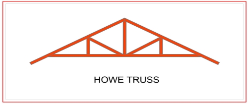
(i) Howe truss
(ii) Simple fink truss
(iii)Compound French truss
(vi) Simple tan truss
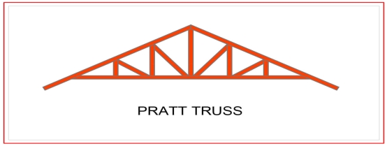
(v) Pratt truss
(vi) Compound fink truss
(vii) North-light truss etc.
3. Water tank:
They may be circular, rectangular or spherical. They may rest on the ground or be elevated. The function of water tank is to contain material.
4. Bridges:
The truss and plate-girder bridges are commonly used for small to moderate spans, cable-stayed and suspension bridges for long spans. Sometimes arch bridge and cantilever bridge are also used. Foot Bridge is very common in a railway station. The function of bridge is to provide runway.
5. Gantry girder:
The travelling overhead cranes are commonly used in workshops and factories. The function and gantry girder is to lift and move the heavy materials and machinery from one place to other.
6. Column:
These are the members that resist compressive components of loads in a truss, and bridge piers. In building structure loads and moments are transmitted to column through beams. Generally a compound column is used consisting of channels placed face to face or back to back. The two components must be tied together with the help of lacing or battening. The function of column is to give support.
Key takeaways:
- Towers may be self-supporting or cable-stayed. Towers are made of steel angles or tubes, bolted at site.
- These are the members that resist compressive components of loads in a truss, and bridge piers.
GRADES OF STRUCUTURAL STEEL-
The most common is Hot Rolled Medium and High Tensile Structural Steel conforming to IS: 2062.
This is used in steel structures in India.
You get these steels with varying chemical composition and mechanical properties and they are designated further by Grades.
The available grades are Grade 250 up to Grade 650.
The yield strengths start from 250MPa going up to 650 MPa.
The most commonly used grade is 250.
But for steel used as reinforcement in RCC construction the material grades are
IS 432 for mild steel medium tensile bars and
IS: 1786 for High strength deformed bars
Structural steel other than those specified under mild steel and high tensile steel conforming to wieldable quality may also be used provided that the permissible stresses and other design provisions are suitably modified and the steel is suitable for the type of fabrication adopted.
In this unit mild steel and high tensile steel are considered for the design.
The chemical composition of structural steel
Types of steel | Designation | IS Codes | C (Max) | Mn (Max) | S (max) | P (Max) | Si (Max) | Carbon equivalent |
Standard | Fe 410 A | 2062 | 0.23 | 1.5 | 0.050 | 0.050 | 0.4 | SK 0.42 |
Structure | Fe 410 B | 2062 | 0.22 | 1.5 | 0.045 | 0.045 | 0.4 | SK 0.41 |
Steel(IS 2062) | Fe 410 C | 2062 | 0.20 | 1.5 | 0.040 | 0.040 | 0.4 | K 0.39 |
Micro alloyed medium high strength steel | Fe 440 | 8500 | 0.20 | 1.5 | 0.050 | 0.050 | 0.45 | 0.40 |
Fe540 | 8500 | 0.20 | 1.5 | 0.045 | 0.045 | 0.45 | 0.44 | |
Fe 590 | 8500 | 0.20 | 1.5 | 0.045 | 0.045 | 0.45 | 0.48 |
Where,
Fe Stands for steel and the number after Fe is the tensile strength in N/mm^2 or MPa
K: killed steel
SK: Semi killed steel
C= Carbon
Mn = Manganese
S= Sulphur
P= phosphorus
Si= silicon
Structural Steel has been classified based on its ultimate or yield strength
e.g. Fe 410 Steel means minimum tensile strength of 410 N/mm^2. The mechanical properties of steel is largely depends on its chemical composition given below
Types of steel | Designation | UTS | Yield strength (MPa) Thickness (mm)/(<20 20-40>40) | Min. Percentage elongation gauge length = 5.65(A0)^2 | Charpy V notch impact energy (min) | ||
Standard | Fe 410 A | 410 | 250 | 240 | 230 | 23 | - |
Structure | Fe 410 B | 410 | 250 | 240 | 230 | 23 | 27 |
Steel (IS2062) | Fe 410 c | 410 | 250 | 240 | 230 | 23 | 27 |
Micro alloyed | Fe 440 B | 440 | 300 | 290 | 280 | 22 | 30 |
Medium/High | Fe 540 B | 540 | 410 | 390 | 380 | 20 | 25 |
Standard Steel | Fe 490 B | 490 | 350 | 330 | 320 | 22 | 25
|
Key takeaways:
Structural steel other than those specified under mild steel and high tensile steel conforming to weld able quality may also be used provided that the permissible stresses
There are various types of rolled steel sections which are listed below-
1- Rolled steel beam sections
2- Rolled steel channel sections
3- Rolled steel angle sections
4- Rolled steel Tee sections
5- Rolled steel bar
6- Rolled steel plates
7- Rolled steel flats
1- Rolled steel beam sections- they are various types which has various properties such as weight dimensions are given in steel table –
- Indian standard junior beams(ISJB)
- Indian standard light beams(ISLB)
- Indian standard medium beams(ISMB)
- Indian standard wide flange beams(ISWB)
- Indian standard heavy beams(ISHB)
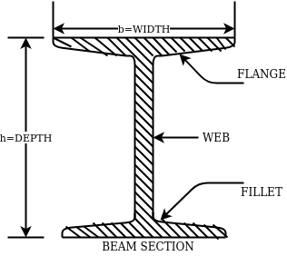
The above fig shows a typical beam, section. These section are designated by depth in mm and weight per metre run for example
ISMB500@0.852kg/m where 500 represents its depth in mm and 0.852 show uniformly distributed load per metre run.
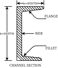
2- Rolled steel channel sections-
They are classified into 4 groups-
- Indian standard junior channel (ISJC)
- Indian standard light channel (ISLC)
- Indian standard medium weight channel(ISMC)
- Indian standard special channel(ISSC)
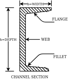
They are also designated by depth and weight for example ISMC250@0.450kN/m.
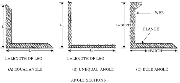
3- Rolled steel angle sections-
They are classified into 2 series-
- Indian standard equal angle (ISA)
- Indian standard unequal angle (ISA)
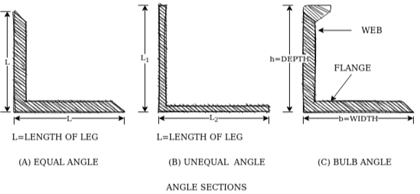
For equal angle section-
ISA150*150*12mm
For unequal angle section-
ISA90*75*8mm
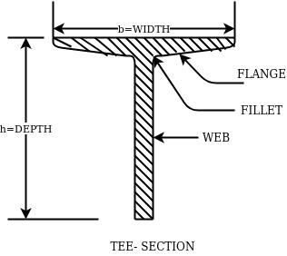
4- Rolled steel Tee sections-
They are categorized into 5 series-
- Indian standard normal Tee bars (ISNT)
- Indian standard heavy flanged tee bars (ISHT)
- Indian standard light tee bars(ISLT)
- Indian standard junior tee bars (ISJT)
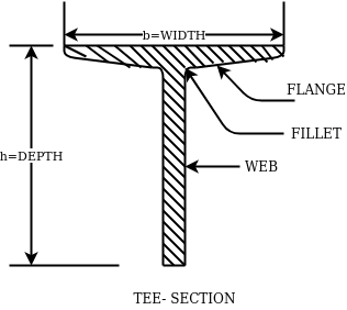
The rolled steel sections are designated by the series to which they belong followed by depth and weight per metre length.
Ex. ISNT60@53N/m
5- Rolled steel bars-
They are 2 types-
- Indian standard round bars (ISRO)
- Indian standard square bars (ISSQ)
Rolled steel bars are designated by ISRO followed by diameter in case of round bars and ISSQ followed by side width in case of square bars.
Example-ISRO10
ISSQ20
6- Rolled steel plates-
Rolled steel plates of following thicknesses are available such as 5,6,8,10,12,14,16,20,22,25,28,32,36,40,45,50,56,63,71, 80mm.they are rolled in widths 160,180,220,280,320 etc.
These plates are designated by ISPL followed by length,width, thickness. For example-ISPL2000*1000*6
7- Rolled steel flats-
They are designed by width followed by letters ISF and thickness.
For example- 80ISF 10 means 80mm wide flat for thickness 10mm.
Key takeaways:
Rolled steel bars are designated by ISRO followed by diameter in case of round bars and ISSQ followed by side width in case of square bars.
The latest version of the Code of Practice for general construction in steel IS: 800-2007 is based on Limit State Method of design. The design concept is totally changed in comparison to earlier code IS 800:1984 which is based on Elastic method.
IS: 800: 2007 – Code of Practice for general construction in Steel
This standard applies to general construction using hot rolled steel sections joined using riveting, bolting and welding. Specific provisions for bridges, chimneys, cranes, tanks, transmission line towers, bulk storage structures, tubular structures, cold formed light gauge steel sections, etc, are covered in separate standards.
This standard gives only general guidance as regards the various loads to be considered in design. For the actual loads and load combinations to be used, reference may be made to IS 875 for dead, live, snow and wind loads and to IS 1893 (Part 1) for earthquake loads.
IS: 808: 1989 – Dimensions for Hot Rolled Steel Beam, Column, Channel and Angle Sections.
IS:875 PART-I- DEAD LOADS - UNIT WEIGHTS OF BUILDING MATERIALS AND STORED MATERIALS.
IS:875 PART-II- code of practice for design loads (other than earthquake loads) for building and structures part 2 imposed loads
IS:875 PART-III- code of practice for design loads (other than earthquake loads) for building and structures part 3 wind loads.
IS 816–1969
Butt weld
This sort of weld is used while the contributors are in identical plane. Butt weld is likewise termed as groove weld. The butt weld is used to sign up for structural contributors wearing direct compression or tension. It is used to make tee-joint and butt-joint. The following forms of butt welds are in practice. These are named relying upon form of the grove made for welding.
Key takeaways:
The latest version of the Code of Practice for general construction in steel IS: 800-2007 is based on Limit State Method of design.
1. Plastic Analysis
Plastic layout is a way via way of means of which structural factors are decided on thinking about the system's ordinary final capacity. For safety, the implemented masses are in- creased via way of means of load elements dictated via way of means of suitable codes. This layout is primarily based totally at the yield belongings of the steel.
Plastic layout of metallic systems might also additionally count on distinctive ranges of complexity and sophistication. In this bankruptcy, techniques of evaluation and structural fashions primarily based totally on beam concept are presented. Plastic evaluation of systems may be performed with distinctive tiers of sophistication. The techniques of plastic evaluation may be primarily based totally at the static theorem or most principle, and the kinematic theorem or minimal principle. Plastic layout of metallic systems is frequently used withinside the layout of pitched-roof portal frames. The bankruptcy describes the verification techniques for contributors and additives that comprise capacity plastic hinges, being an crucial function of plastic layout. General standards for the verification of the stableness of contributors with plastic hinges, in addition to policies for bracings, are presented. Because of the complexity of such verifications and capacity lack of resistance and consequently economy, a not unusual place system is to save you out-of-aircraft buckling via way of means of the usage of good enough bracings.
The major distinction among elastic and plastic deign is the idea of the conduct of the shape. In elastic layout we anticipate that shape will fail if it reaches elastic restrict however in plastic evaluation we keep in mind that shape will fail while it reaches decrease yield point. In plastic layout we should keep in mind the deformed form of the shape and examine the secondary masses evolved because of the deformation. Here we additionally speak approximately the Shape Factors (S= Plastic Moment/ Yield Moment) for one of a kind form of sections like it is able to be one of a kind for square phase, I-Section, Circular Section etc. The essential situations of plastic evaluation are a) Equilibrium Condition: b) Yield Condition: At crumble, bending second at any phase ought to now no longer exceed the plastic second capability of the beam cross- phase. (Mp) c) Mechanism Condition: At the crumble condition, enough no of plastic hinges need to be evolved in order that a element or whole shape need to rework right into a mechanism, main to crumble. Theorem of Plastic Analysis: A) Static Theorem (Lower Bound Theorem) Static Theorem satisfies equilibrium and yield situations. It states that the crumble load observed on the premise of crumble B.M.D (wherein B.M at any phase is much less than or identical to Mp) will constantly be much less than or identical to crumble load. (P£ Pu). Static technique represents the decrease restrict of actual final load and has most aspect of safety. B) Kinematic Theorem (Upper Bound Theorem): Here equilibrium and mechanism situations are satisfied. It states that the crumble load observed via way of means of assuming the mechanism will constantly be more than or identical to the crumble load (P³ Pu). Where, P= Calculated crumble load, Pu = True crumble load
2. Plastic hinge formation
1. Plastic Theory
Plastic analysis will be introduced that behavior of steel beams & frames in the plastic range.
2. Terminology
Plasticity – It is defined as the state of permanent deformation without fracture in a material caused by the stresses which are greater than the yield stresses.
Plastic -Hinge – when the entire c/s of the beam becomes fully plastic on infinitely small increased in applied moment would cause large increases in curvature this effect is plastic hinge.
Plastic moment – The bending moment required to develop of plastic hinge is known as plastic moment. Denoted by Mp
Plastic collapse – It is also called collapse mechanism it is a condition of which the indefinite deflection occurs of construction load
Plastic collapse level – The load at which plastic collapse occurs is the plastic load it denoted by wu.
Load factor – It is the ratio of the collapse load to the working load.
It is assumption of plastic theory.
- The material is ductile of elastic plastic
- Strain hardening is neglected
- The deformations are small
- The beam is initially straight
- The beam is bending by pure bending the influence of axial force & shear on the plastic moment is neglected.
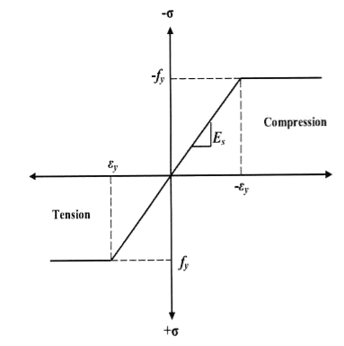
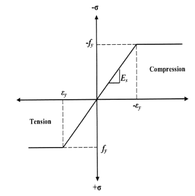
- The stress strain relation is ideal as bilinear in tension as well as company
- The loading is proportional.
Diagram
Consider a rectangular beam width of b and depth d subjected to steadily increasing load w over a simply supported span l
Stress stain diagrams shows elastic stress distribution for working and service load hence 
Where f= working stress
Further increases in load caused stress level fy at extreme fiber as shown in fig. This is the limit of elasticity
Therefore elasticity moment of resistance 

For rectangular section 
Further increases in load a does not produce increase in stress as fy remains constant as per idealize stress strain curve but strains increases thus stress is in the fiber immediately below the extreme fiber now reaches to fy
Yielding penetrated inside the fiber this is called elasto plastic range
Further increase in load causes yielding inside the cross section over the depth and the stress distribution is rectangular in both compression as well as tension this stage is known as fully plastic range and the moment at this stage is called plastic range
Moment at fully plastic stage is given by


For rectangular section C = total compressive force
= 
T= total tensile force= 
a = lever arm (y1+y2)
For rectangular section


Where Zp= plastic sectional modulus = 
Concurrently yielding also penetrated is adjoining cross section on either side
Here section
EE fully elastic range/stage
DD elasto plastic range /stage
CC fully plastic range/stage
When yielding of section takes place over entire depth
Section CC behaves similar to mechanical hinge called plastic hinge but at this plastic hinge moment is constant and it is denoted by Mp
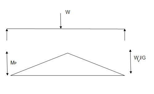
Excessive rotation at C due to deformation of plastic hinge transform structure in to mechanism called as collapse mechanism. At this stage load w reaches to wp is called plastic collapse load


Now,
It is seen that rectangular section using equation

Thus the plastic stage rectangular section has 50% more strength compare to that of elastic stage.
Example
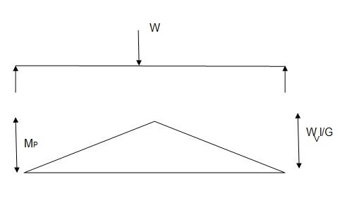
A S.S. Beam is determinate she. Formation of one hinge in the beam created collapse mechanism since, the maximum moment under the load the hinge will form at the place.

3. Shape factor
Shape factor:
It is ratio of plastic moment carrying capacity (Mp) to the yield moment (Me) of a section.
S = 
Shape factor –
It is defined as the of plastic moment of a section to the yield moment of the section
S = =  =
= 
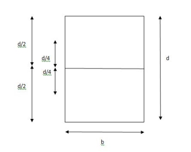
Shape factor for Rectangular section.
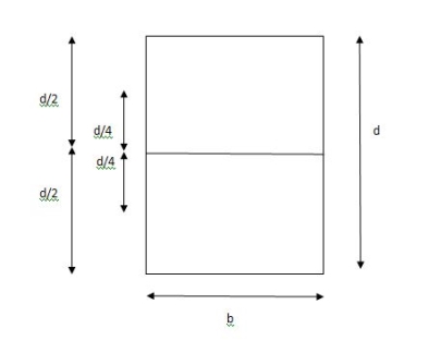
S = 
Zp = A/2 (y1 + y2)
= 
= bd2/4
Z = bd2/6
S = bd2/4 6/bd2 = 1.5
Shape factor of 1.5 Rectangular
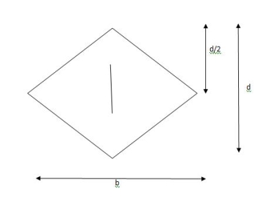
Shape factor of Diamond section
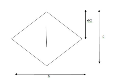
S = 
Zp = A/2 (y1 + y2)
= 
= bd2/6
Shape factor= 2 for Diamond
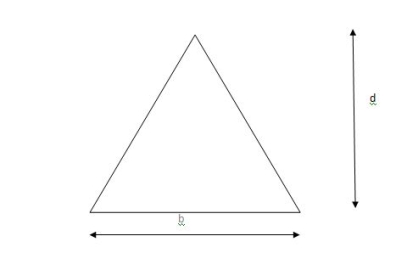
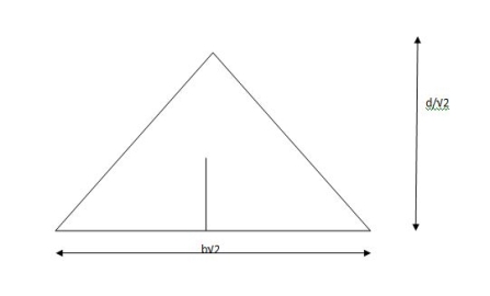
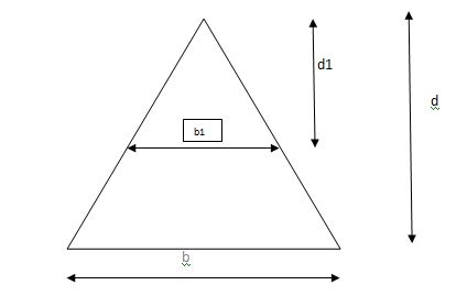
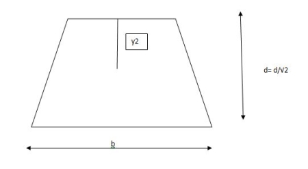
Shape factor for Triangle
Z = 
Diagram
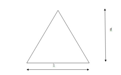
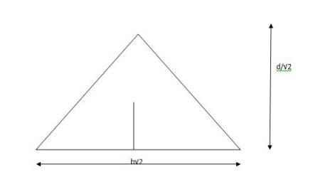
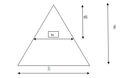
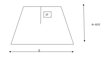
y2 = 
y2 = 0.1553
Zp = A/2 ( y1 + y2)
= 
Zp = 0.09775 bd2
S = Zp/Z = 2.346
Shape factor of triangle = 2.346
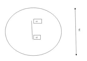
Shape factor for circular section
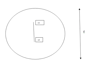
S = Zp/Z
Z= 1/Y = πD2/2 2/D = πD3/32
ZP = π/4 D2/2 [4r/3π + 4r/3π]
= π/4 D2/2 [2/3 D/3π + 2D/3π]
π/4 D2/2 [4D/3π] = D3/6
Collapse mechanism for beams
In the mechanism or kinematic approach of plastic analysis, numerous plastic failure mechanisms are evaluated. The plastic fall apart hundreds similar to numerous failure mechanisms are acquired with the aid of using equating the inner paintings on the plastic hinges to the 10W 10 W 6W 2T 3T 5T outside paintings with the aid of using hundreds in the course of the digital displacement. This calls for assessment of displacements and plastic hinge rotations. For gabled frames and different such frames, the kinematics of fall apart is somewhat complex. It is handy to apply the immediate centres of rotation of the inflexible elements of the body to assess displacements similar to one of a kind mechanisms. In this, homes of rotations of a inflexible frame in the course of an infinitesimally small perspective T
Fall apart*L/4. Then (0.50Mp+Mp)+ Pp*L/4, 2 will go together with 2, Mp=(1/6)*Pp*L. The Plastic Load or the fall apart load Pp=6*Mp/L.
Plastic analysis of determinate beam:
Examples
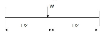
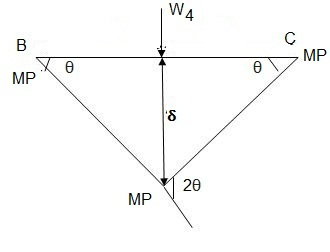
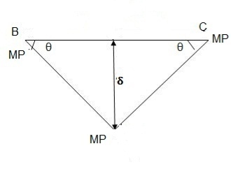
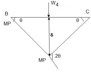
1. Determine load (Wu) using mechanism method of a simply supported beam subjected to point load at centre.

Solution:
- Number of plastic hinges required to collapse n= r+1 =1
- N=1
- n= N-r= 1
- Using virtual work principle


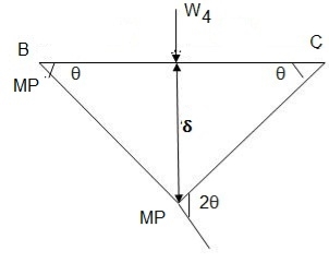
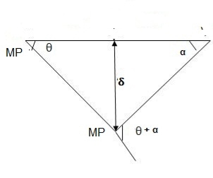
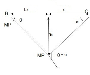
2. Determine collapse load (Wu) of a simply supported beam subjected to eccentric load.

Solution:
- Number of plastic hinge required to collapse n= r+1=1
- N=1
- N=n
- Using virtual work principle


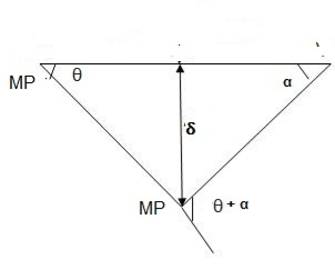
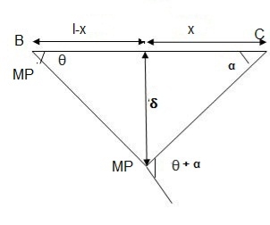
Using virtual work principle


3. Determine collapse load of a simply supported beam subjected to udl over span.

Solution:
- n= r+1=1
- N= 1
- N=n
- Virtual work principle

Average deformation
But 


B. Plastic analysis of indeterminate beams
Examples:
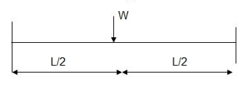
1. Determine true collapse load of a propped cantilever beam subjected to load at centre.
Solution:
- n=r+1 =2
- N=2
- N=n
- Using virtual work principle

But

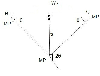
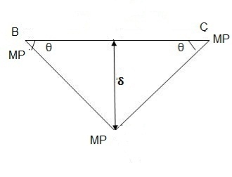
2. Determine true collapse load of a fixed beam subjected to udl

Solution:
- n=r+1= 3
- N=3
- N=n
- Using virtual work principle


Where Wu= W.L = total UDL
(a) Tension members
Design strength due to gross section yielding (IS800-2007, Cl.6.2)
Steel members (plates, angles, etc) without bolt holes an sustain loads up to ultimate load without failure. However, the members will elongate considerably (10to15% of its original length) at this load and hence make the structure unserviceable. Hence the design strength Tdg is limited to the yielding of gross section which is given by,

Where
 = yield strength of the material in MPa
 = gross area of cross section in mm^2
 = 1.10= partial safety factor for failure at yielding
Design strength due to net section rupture
This occurs when the tension member is connected to the main or other members by bolts or weld. The holes made in members for bolt will reduce the cross section and hence net area will govern the failure in this case.
Design strength in tension of a plate

Step1-find the required gross area to carry the factored load considering strength in yielding –
Ag= 1.1 Tu/fy
Tu= factored tensile force
Step2-select suitable shape of the section depending upon the type of structure and the location of the member such that gross area is 25 to 40% more than Ag calculated.
Step3- determine the no. Of bolts or welding required.
Step4-find the strength considering –
1- Strength in yielding
2- Strength in rupture of critical section
3- Strength of block shear
If design is safe if Ag provided < Ag required
Step5- the strength obtained should be more than that factored tension
Step6- IS800:2007 also recommends the check for slenderness ratio of tension member as shown in table below-
Sr no. | Member | Max. Ur |
1. | A tension member in which a reversal of direct stress occurs due to load other than wind or seismic forces | 180 |
2. | A member normally acting as a tie in a roof truss or a bracing system not considered effective when subject to possible reversal of stress into compression resulting from the action of wind and earthquake forces. | 350 |
3. | Members always under tensions other than pretensioned members | 400 |
4. | Tension members, such as bracing, pretensioned to avoid sag , need not satisfy the maximum slenderness ratio limit | No limit |
Examples:
Q.1 Design bolted connection for single angle ISA 90 x 90x 6 mm @ 8.2 kg/m carrying factored axial tension 115 KN with 8 mm thick gusset plate. Use M16 bolt of property class 4.6
Solution:
Given
- Properties of cross section
ISA 90x90x6 mm @ 8.2 kg/m
Ultimate strength of bolt fub= 400 MPa
Ultimate strength of steel fu= 410 MPa


d = 16mm
d0= 18 mm
2. Design of bolted connection
- Shear strength of bolt


b. Bearing strength of bolt
a) 
b) 


Bolt value = least of V dsb and V dpb= 28.97 kN
Number of bolt required = 115/28.97 = 3.96 = 4 bolts
Q.2 A tie member of a truss 2ISA 65x65x6 @ 5.8 kg/m back to back on either side is welded to gusset plate. Design a weld to transmit a load equal to the full strength of the member.
Solution:
- Design tensile strength due to yielding of gross cross section

2. Design of welded connection
From tableIS 800-2007
Assume size of weld= 6 mm
By equating,


But

Taking moment about C.G


By using equation


b. Compression Member
Strength of compression member
The power of a compression member is described as its secure load sporting potential. The power of a centrally loaded immediately metal column relies upon at the powerful cross-sectional place, radius of gyration (viz., form of the cross-phase), the powerful duration, the importance and distribution of residual stresses, annealing, out of straightness and bloodless straightening.
The powerful cross-sectional place and the slenderness ratio of the compression contributors are the primary features, which have an effect on its power.
In case, the allowable stress is thought to differ parabolic ally with the slenderness ratio, it could be proved that the performance of a form of a compression member is associated with A/r2.
The performance of a form is described because the ratio of the allowable load for a given slenderness ratio to that for slenderness ratio identical to zero. The secure load sporting potential of compression member of recognized sectional place can be decided as follows:
Step1]
From the actual duration of the compression member and the guide situations of the member, that are recognized, the powerful duration of the member is computed.
Step 2]
From the radius of gyration approximately diverse axes of the phase given in phase tables, the minimum radius of gyration (rmin) is taken. rmin for a constructed-upphase is calculated.
Step 3]
The most slenderness ratio (l/ rmin) is decided for the compression member.
Step 4]
The allowable running stress (σac) within side the route of compression is found similar to the most slenderness ratio of the column from IS:800-1984.
Step 5]
The powerful sectional place (A) of the member is stated from structural metal phase tables. For the constructed-up contributors it could be calculated.
Step 6]
The secure load sporting potential of the member is decided as P= (σac. A), where P=secure load
Q.1 A single angle discontinuous strut ISA 150 mm x 150 mm x 12 mm (ISA 150 150, @0.272 kN/m) with single riveted connection is 3.5 m long. Calculate safe load carrying capacity of the section.
Solution:
Step 1: Properties of angle section
ISA 150 mm x 150 mm x 12 mm (ISA 150 150, @0.272 kN/m) is used as discontinuous strut. From the steel tables, the geometrical properties of the section are as follows:
Sectional area A = 3459 mm2
Radius of gyration rxx= ryy=149.3 mm
Radius of gyration ruu= 58.3 mm, rvv=29.3 mm
Step 2: Slenderness ratio,
Minimum radius of gyration rmin= 29.3 mm
Effective length of strut l= 3.5 m
Slenderness ratio of the strut
Step 3: Safe load
From IS:800-1984 for l/r=119.5 and the steel having yield stress, fy=260 N/mm2, allowable working stress in compression σac =64.45 N/mm2 (MPa)
For single angle discontinuous strut with single riveted connection, allowable working stress
0.80 σac = (0.80 x 64.45) = 51.56 N/mm2.
The safe load carrying capacity

Q.2 In case in Example 1, a discontinuous strut 150 x 150 x 15 angle section is used, calculate the safe load carrying capacity of the section.
Solution:
Step 1: Properties of angle section
Angle section 150 mm x 150 mm x 15 mm is used as discontinuous strut. From the steel tables, the geometrical properties of the section are as follows:
Sectional area A = 4300 mm2
Radius of gyration rxx= ryy=45.7 mm
Radius of gyration ruu= 57.6 mm, rvv=29.3 mm
Step 2: Slenderness ratio,
Minimum radius of gyration rmin= 29.3 mm
Effective length of strut l= 3.5 m
Slenderness ratio of the strut

Step 3: Safe load
From IS: 800-1984 for l/r=119.5 and the steel having yield stress, fy=260 N/mm2, allowable working stress in compression σac =64.45 N/mm2 (MPa)
For single angle discontinuous strut with single riveted connection, allowable working stress
0.80 σac = (0.80 x 64.45) = 51.56 N/mm2.
The safe load carrying capacity

Q.3 In Example 1, if single angle discontinuous strut is connected with more than two rivets in line along the angle at each end, calculate the safe load carrying capacity of the section.
Solution:
Step 1: Properties of angle section
Discontinuous strut ISA 150 mm x 150 mm x 12 mm (ISA 150 150, @0.272 kN/m) is used with double riveted connections. From the steel tables, the geometrical properties of the section are as follows:
Sectional area A = 3459 mm2
Radius of gyration rxx= ryy=149.3 mm
Radius of gyration ruu= 58.3 mm, rvv=29.3 mm
Length of strut between center to center of intersection L=3.50 m
Step 2: Slenderness ratio,
Minimum radius of gyration rmin= 29.3 mm
Effective length of discontinuous strut double riveted 0.85 x L= 0.85 x 3.5 = 2.975 m
Slenderness ratio of the strut

Step 3: Safe load
From IS:800-1984 for l/r=101.5 and the steel having yield stress, fy=260 N/mm2, allowable working stress in compression σac =71.65 N/mm2 (MPa)
Allowable working stress for discontinuous strut double riveted is not reduced.
The safe load carrying capacity 
Q.4 A double angle discontinuous strut ISA 125 mm x 95 mm x 10 mm (ISA 125 95, @0.165 kN/m) long legs back-to-back is connected to both the sides of a gusset plate 10 mm thick with 2 rivets. The length of strut between center to center of intersections is 4 m. Determine the safe load carrying capacity of the section.
Solution:
Step 1: Properties of angle section
The double angle discontinuous strut 2 ISA 125 mm x 95 mm x 10 mm (ISA 125 95, @0.165 kN/m) is shown in Fig. 11.4. Assume the tacking rivets are used along the length. From the steel tables, the geometrical properties of (two angle back-to-back) the sections are as follows:
Sectional area A = 4204 mm2
Radius of gyration rxx= 39.4 mm
Angles are 10 mm apart
Radius of gyration ryy= 40.1 mm
Length of strut between center to center of intersection L=4 m
Step 2: Slenderness ratio,
Minimum radius of gyration rmin= 39.4 mm
Effective length of discontinuous strut 0.85 x L= 0.85 x 4.0 = 3.40 m
Slenderness ratio of the strut

Step 3: Safe load
From IS:800-1984 for l/r=86.3 and the steel having yield stress, fy=260 N/mm2, allowable working stress in compression σac =95.96 N/mm2 (MPa)
The safe load carrying capacity

ROOF TRUSS-
The function of a truss is to transfer load from point of application to the supports as directly as possible. Thus for a concentrated load at the centerline of a span, a simple “A” frame is the most efficient. Like-wise, if only two equal and symmetrically placed concentrated loads are involved, a truss similar to the queen-post type is the most efficient. In both trusses, the load is transferred to the support directly through the sloping top-chord members without the need for web members.
[1] WALL PLATE / BEARIG
The first timber to be placed, it’s always horizontal and it’s placed at top of the external walls. Structural support of trusses (usually walls) normally with a timber wall plate.
[2] TYE BEAM / BOTTOM CHORD
Almost same as wall plate, but it’s not place on the wall it’s most time 1.2m apart, purposely use for the placement of ceiling. Horizontal along the spacing of the building. The tye beam is place after the wall plate.
[3] RAFTER / TOP CHORD
The rafter is in slant form always from one edge of the wall plate to another all meeting at the top of the key post. It’s also most time 1.2m apart.
[4] WEBS
Members that join the top and bottom chords to form a triangular pattern.
[5] PURLINS / BATTENS
It’s always been the last. It is put horizontally across the rafter. Which is most time 0.9m apart.
[6] APEX
Highest point where the sloping top chords meet.
[7] CANTILEVER
Part of structural member that extends beyond its support.
ROOF TRUSS TYPES-
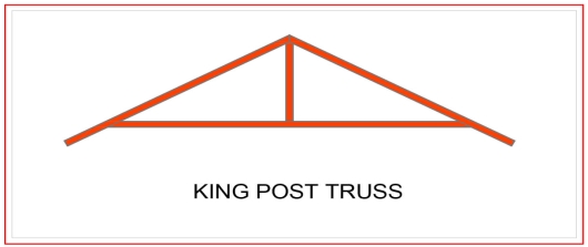
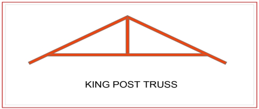
King Post Truss
Central vertical post used in architectural, working in tension to support a beam below from a truss apex. This truss usually spans up to 8 meters, which makes it perfect for multiple types of houses, especially the smaller ones.
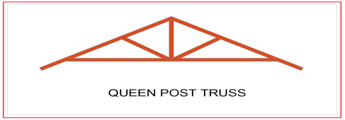
Queen Post Truss
A very reliable, simple and versatile type of roof truss where you can use at any given time. This kind of truss offers a span of around 10 meters, and has a simple design which makes it perfect for a wide range of establishments.
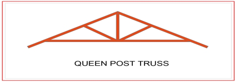
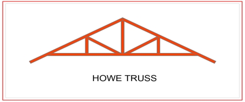
Howe Truss
A kind of truss having upper and lower members, a combination of steel and wood or both. One thing that makes this truss extraordinary is that it has a very wide span, as it can cover anything from 6-30 meters. This is very useful for a wide range of project types.
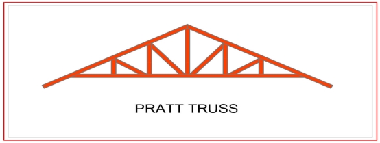
Pratt Truss
The prat truss is the most popular steel truss since it is very economical. It includes vertical and diagonal members that slope down towards the center (opposite of Howe Truss). Pratt truss can cover lengths ranging between 6-10 meters.
1. DEAD LOADS-
It includes the weight of sheeting purlins bracings, self weight and other loads suspended from trusses.
The unit weight of various material are given in IS875 part is. The following values may be noted-
GI sheets 85N/m2
AC sheets 130N/m2
In general the roof covering weight including lap, connectors etc may be taken as
1- 100-150 N/m2 for GI sheeting
2- 170-200N/m2 for A C sheeting
Weight of purlin should be added after designing purlin. Generally it works out 100-200N/m2 of plan area.
There are various formulae suggested to assume the self weight of the truss. These formulae economically used for a truss of span L
1- W=20+6.6L N/m2 for a LL of 2KN/m2
2- W=10(L/3 +5) s/4 N/m2 if LL is more than above value
Where s= spacing of truss
2. LIVE LOAD (IMPOSED LOAD)
IS875 part II makes the following provisions for live loads for the design of sheets and purlins.
Upto 10 degree slope -0.75kN/m2
For more than 10 degree slope -0.75-0.02(α-10)
Where α is the slope of sheeting
However a minimum of 0.4 Kn/m2 live load should be considered in any case.
For the design of truss the above live load may be reduced to 2/3 radians
The purlins and sheets should be checked to support a concentrated load of 0.9 kN at the worst position.
3. WIND LOAD-
IS875 part III gives the guidelines to determine wind forces on different components of buildings . It consists of the following steps
a- Determine basic wind speed
b- Obtain design wind speed
c- Calculate design wind pressure
d- Calculate wind pressure on roof
The steps are explained below-
a- Determine basic wind speed-(Vb)
For finding basic wind pressure in any place of india IS 875 par III divides the country into six zones as shown in fig. it is based on peak gust velocity averaged over a short time interval of about 3 seocnds studied over a period of 50 years . The value correspond to the speed at 10m height above ground level and in open terrain. For imp cities the basic wind pressure are given in the code. It may be observed that highest basic wind speed is 55m/s and lowest is 33 m/sec
b- Design wind speed (Vt)
The design wind speed of any site may be
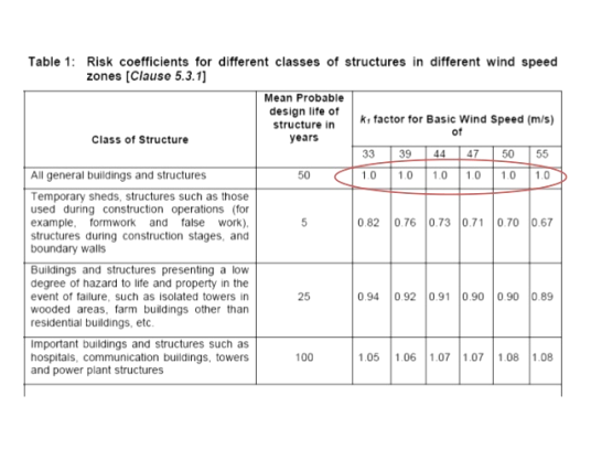
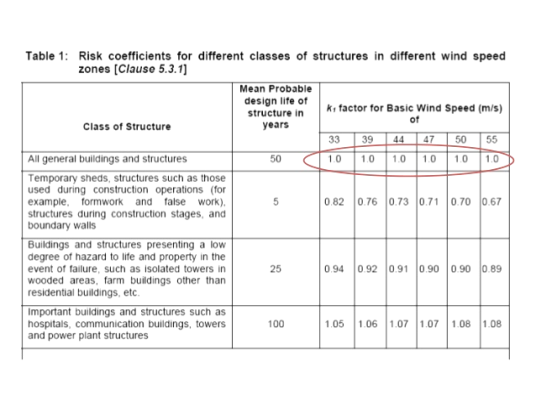
Vt=k1 k2 k3 Vb
Where k1= risk coefficient
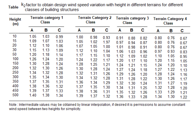
K2= terrain, height and structure
K3=topography factor
Risk coefficient (k1)-depending upon the importance of the building and basic wind speed IS875 has developed an equation to determine risk coefficient k1 for different types of buildings. These values shown in the table-
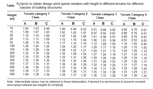
Terrain, height and structure size factor (k2)-
This coefficient depends upon terrain of the building site , height of the building and site of the building and class of building.
Buildings are classified into various classes-
Class A-buildings having maximum dimension less than 20m
Class B-Building having maximum dimension between 20 to 50m
Class C- building having maximum dimension greater than 50m
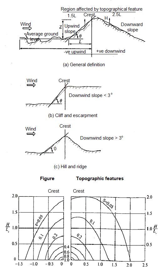
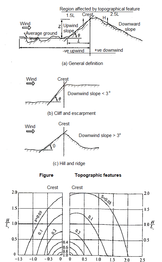
Topography factor (k3)-this factor is to account for the topographic features which influence design wind speed . Topographic features such as hills , valleys , cliffs etc
c- wind pressure-
The design wind pressure at any height above means ground level shall be calculated by following equation-
Pz=0.6 Vz2
Where
Pz=design wind pressure in N/m2at height z
Vz= design wind velocity in m/sec at height z
d- wind pressure on roof-
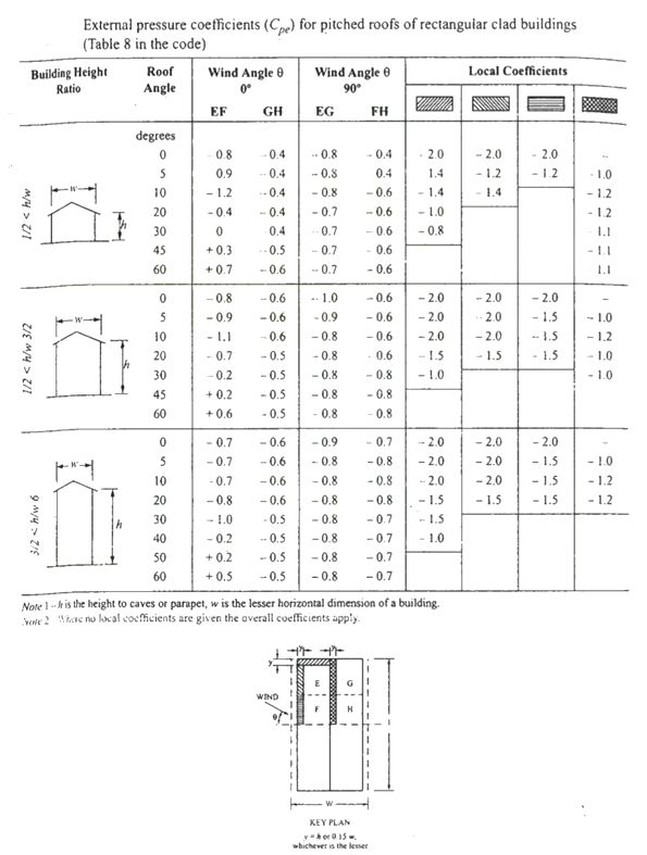
For calculating the wind load on individual structural elements it is essential to take into account of pressure difference between opposite faces of such elements. If internal as well as external pressure are found then wind load acting in a direction normal to the individual structural element is-
F=(Cpe - Cpi) A pd
Where Cpe= external pressure coefficient
Cpi= internal pressure coefficient
A= surface area
Pd=design wind pressure (N/m2)
Buildings with Cpi
Low permeability (less than 5% openings in wall area) ± 0.2
Medium permeability (5 – 20 % opening in wall) ± 0.5
Large openings (openings > 20% in wall) ±0.7

Key takeaways:
For the design of truss the above live load may be reduced to 2/3 radians
The purlins and sheets should be checked to support a concentrated load of 0.9 kN at the worst position.
References:
1. Design of Steel Structure, N Subramanian, Oxford University Press, New Delhi
2. Limit State Design in Structural Steel, M. R. Shiyekar, PHI, Delhi
3. Fundamentals of structural steel design, M L Gambhir, Tata McGraw Hill Education Private limited, New Delhi.
4. Structural Design in Steel, Sarwar Alam Raz, New Age International Publisher
5. Limit State Design of Steel Structure, V L Shah & Gore, Structures Publication, Pune
Unit - 1
Steel as a structural material
Firstly it’s useful to recognize what structural metal absolutely is and the way it's miles formed. Structural metal shapes are comprised of this type of metal that is formatted from a specific move section. Yet, on the identical time it follows exact requirements for mechanical homes and chemical composition. Structural metal is available in numerous shapes like L-beam, Z shape, HSS shape, L shape (angle), structural channel (C-beam, move section), T shaped, rail profile, bar, rod, plate and an open joist of internet metal.
Standard structural metallic varies in one-of-a-kind international locations with numerous specifications. For example, European I-beam is Euronorm 19-57, while structural metallic within side the USA is available in carbon, low alloy, corrosion resistant excessive power low alloy, quenched and tempered alloy metallic etc. Structural metallic is versatile, sturdy and durable, so it is infrequently sudden that it is able to be morphed into nearly any form primarily based totally on the development task at hand; it is able to be built nearly straight away the instant it's miles obtained at the constructing site. Structural metallic is hearth place-resistant in itself however hearth place safety strategies must be installed vicinity in case there may be a opportunity of it getting heated up to some extent wherein it begins off evolved to lose its sturdiness and power.
Corrosion must be avoided in terms of structural metallic, however tall homes are regarded to have withstood diverse types of adversities while constructed the usage of structural metallic. Steel creation is growing in reputation everywhere in the world, with each area benefitting from metallic for the duration of the years. Many of the quality architectural wonders were built through the usage of metallic, be it structural, carbon or rebar, together with The Empire State Building and the Sydney Harbor Bridge. More importantly, using metallic is useful in phrases of eco friendliness than different modes of creation, and because of this aspect alone, it's far given extra preference. Taking into attention the charge of marvelous constructions, metallic has proved favorable. With using metallic growing within side the creation industry, there may be absolute confidence that it's going to take over the whole creation discipline quickly within side the future.
Types of steel structures
1. Tower:
Towers may be self-supporting or cable-stayed. Towers are made of steel angles or tubes, bolted at site. Towers are of different types such as telephone tower, windmill tower, observation towers, lighting towers, power transmission towers etc. The function of tower is to provide support.
2. Roof truss:
A truss is a framed structure consisting of different members like tie, principal rafter, strut and slings; forming triangles i.e. a perfect frame. The steel roof trusses are used when
(1) Span is very large and the beam construction is not economical
(2) The building is in area of heavy rainfall.
Various types of trusses are
(i) Howe truss
(ii) Simple fink truss
(iii)Compound French truss
(vi) Simple tan truss
(v) Pratt truss
(vi) Compound fink truss
(vii) North-light truss etc.
3. Water tank:
They may be circular, rectangular or spherical. They may rest on the ground or be elevated. The function of water tank is to contain material.
4. Bridges:
The truss and plate-girder bridges are commonly used for small to moderate spans, cable-stayed and suspension bridges for long spans. Sometimes arch bridge and cantilever bridge are also used. Foot Bridge is very common in a railway station. The function of bridge is to provide runway.
5. Gantry girder:
The travelling overhead cranes are commonly used in workshops and factories. The function and gantry girder is to lift and move the heavy materials and machinery from one place to other.
6. Column:
These are the members that resist compressive components of loads in a truss, and bridge piers. In building structure loads and moments are transmitted to column through beams. Generally a compound column is used consisting of channels placed face to face or back to back. The two components must be tied together with the help of lacing or battening. The function of column is to give support.
Key takeaways:
- Towers may be self-supporting or cable-stayed. Towers are made of steel angles or tubes, bolted at site.
- These are the members that resist compressive components of loads in a truss, and bridge piers.
GRADES OF STRUCUTURAL STEEL-
The most common is Hot Rolled Medium and High Tensile Structural Steel conforming to IS: 2062.
This is used in steel structures in India.
You get these steels with varying chemical composition and mechanical properties and they are designated further by Grades.
The available grades are Grade 250 up to Grade 650.
The yield strengths start from 250MPa going up to 650 MPa.
The most commonly used grade is 250.
But for steel used as reinforcement in RCC construction the material grades are
IS 432 for mild steel medium tensile bars and
IS: 1786 for High strength deformed bars
Structural steel other than those specified under mild steel and high tensile steel conforming to wieldable quality may also be used provided that the permissible stresses and other design provisions are suitably modified and the steel is suitable for the type of fabrication adopted.
In this unit mild steel and high tensile steel are considered for the design.
The chemical composition of structural steel
Types of steel | Designation | IS Codes | C (Max) | Mn (Max) | S (max) | P (Max) | Si (Max) | Carbon equivalent |
Standard | Fe 410 A | 2062 | 0.23 | 1.5 | 0.050 | 0.050 | 0.4 | SK 0.42 |
Structure | Fe 410 B | 2062 | 0.22 | 1.5 | 0.045 | 0.045 | 0.4 | SK 0.41 |
Steel(IS 2062) | Fe 410 C | 2062 | 0.20 | 1.5 | 0.040 | 0.040 | 0.4 | K 0.39 |
Micro alloyed medium high strength steel | Fe 440 | 8500 | 0.20 | 1.5 | 0.050 | 0.050 | 0.45 | 0.40 |
Fe540 | 8500 | 0.20 | 1.5 | 0.045 | 0.045 | 0.45 | 0.44 | |
Fe 590 | 8500 | 0.20 | 1.5 | 0.045 | 0.045 | 0.45 | 0.48 |
Where,
Fe Stands for steel and the number after Fe is the tensile strength in N/mm^2 or MPa
K: killed steel
SK: Semi killed steel
C= Carbon
Mn = Manganese
S= Sulphur
P= phosphorus
Si= silicon
Structural Steel has been classified based on its ultimate or yield strength
e.g. Fe 410 Steel means minimum tensile strength of 410 N/mm^2. The mechanical properties of steel is largely depends on its chemical composition given below
Types of steel | Designation | UTS | Yield strength (MPa) Thickness (mm)/(<20 20-40>40) | Min. Percentage elongation gauge length = 5.65(A0)^2 | Charpy V notch impact energy (min) | ||
Standard | Fe 410 A | 410 | 250 | 240 | 230 | 23 | - |
Structure | Fe 410 B | 410 | 250 | 240 | 230 | 23 | 27 |
Steel (IS2062) | Fe 410 c | 410 | 250 | 240 | 230 | 23 | 27 |
Micro alloyed | Fe 440 B | 440 | 300 | 290 | 280 | 22 | 30 |
Medium/High | Fe 540 B | 540 | 410 | 390 | 380 | 20 | 25 |
Standard Steel | Fe 490 B | 490 | 350 | 330 | 320 | 22 | 25
|
Key takeaways:
Structural steel other than those specified under mild steel and high tensile steel conforming to weld able quality may also be used provided that the permissible stresses
There are various types of rolled steel sections which are listed below-
1- Rolled steel beam sections
2- Rolled steel channel sections
3- Rolled steel angle sections
4- Rolled steel Tee sections
5- Rolled steel bar
6- Rolled steel plates
7- Rolled steel flats
1- Rolled steel beam sections- they are various types which has various properties such as weight dimensions are given in steel table –
- Indian standard junior beams(ISJB)
- Indian standard light beams(ISLB)
- Indian standard medium beams(ISMB)
- Indian standard wide flange beams(ISWB)
- Indian standard heavy beams(ISHB)
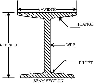
The above fig shows a typical beam, section. These section are designated by depth in mm and weight per metre run for example
ISMB500@0.852kg/m where 500 represents its depth in mm and 0.852 show uniformly distributed load per metre run.
2- Rolled steel channel sections-
They are classified into 4 groups-
- Indian standard junior channel (ISJC)
- Indian standard light channel (ISLC)
- Indian standard medium weight channel(ISMC)
- Indian standard special channel(ISSC)
They are also designated by depth and weight for example ISMC250@0.450kN/m.
3- Rolled steel angle sections-
They are classified into 2 series-
- Indian standard equal angle (ISA)
- Indian standard unequal angle (ISA)
For equal angle section-
ISA150*150*12mm
For unequal angle section-
ISA90*75*8mm
4- Rolled steel Tee sections-
They are categorized into 5 series-
- Indian standard normal Tee bars (ISNT)
- Indian standard heavy flanged tee bars (ISHT)
- Indian standard light tee bars(ISLT)
- Indian standard junior tee bars (ISJT)
The rolled steel sections are designated by the series to which they belong followed by depth and weight per metre length.
Ex. ISNT60@53N/m
5- Rolled steel bars-
They are 2 types-
- Indian standard round bars (ISRO)
- Indian standard square bars (ISSQ)
Rolled steel bars are designated by ISRO followed by diameter in case of round bars and ISSQ followed by side width in case of square bars.
Example-ISRO10
ISSQ20
6- Rolled steel plates-
Rolled steel plates of following thicknesses are available such as 5,6,8,10,12,14,16,20,22,25,28,32,36,40,45,50,56,63,71, 80mm.they are rolled in widths 160,180,220,280,320 etc.
These plates are designated by ISPL followed by length,width, thickness. For example-ISPL2000*1000*6
7- Rolled steel flats-
They are designed by width followed by letters ISF and thickness.
For example- 80ISF 10 means 80mm wide flat for thickness 10mm.
Key takeaways:
Rolled steel bars are designated by ISRO followed by diameter in case of round bars and ISSQ followed by side width in case of square bars.
The latest version of the Code of Practice for general construction in steel IS: 800-2007 is based on Limit State Method of design. The design concept is totally changed in comparison to earlier code IS 800:1984 which is based on Elastic method.
IS: 800: 2007 – Code of Practice for general construction in Steel
This standard applies to general construction using hot rolled steel sections joined using riveting, bolting and welding. Specific provisions for bridges, chimneys, cranes, tanks, transmission line towers, bulk storage structures, tubular structures, cold formed light gauge steel sections, etc, are covered in separate standards.
This standard gives only general guidance as regards the various loads to be considered in design. For the actual loads and load combinations to be used, reference may be made to IS 875 for dead, live, snow and wind loads and to IS 1893 (Part 1) for earthquake loads.
IS: 808: 1989 – Dimensions for Hot Rolled Steel Beam, Column, Channel and Angle Sections.
IS:875 PART-I- DEAD LOADS - UNIT WEIGHTS OF BUILDING MATERIALS AND STORED MATERIALS.
IS:875 PART-II- code of practice for design loads (other than earthquake loads) for building and structures part 2 imposed loads
IS:875 PART-III- code of practice for design loads (other than earthquake loads) for building and structures part 3 wind loads.
IS 816–1969
Butt weld
This sort of weld is used while the contributors are in identical plane. Butt weld is likewise termed as groove weld. The butt weld is used to sign up for structural contributors wearing direct compression or tension. It is used to make tee-joint and butt-joint. The following forms of butt welds are in practice. These are named relying upon form of the grove made for welding.
Key takeaways:
The latest version of the Code of Practice for general construction in steel IS: 800-2007 is based on Limit State Method of design.
1. Plastic Analysis
Plastic layout is a way via way of means of which structural factors are decided on thinking about the system's ordinary final capacity. For safety, the implemented masses are in- creased via way of means of load elements dictated via way of means of suitable codes. This layout is primarily based totally at the yield belongings of the steel.
Plastic layout of metallic systems might also additionally count on distinctive ranges of complexity and sophistication. In this bankruptcy, techniques of evaluation and structural fashions primarily based totally on beam concept are presented. Plastic evaluation of systems may be performed with distinctive tiers of sophistication. The techniques of plastic evaluation may be primarily based totally at the static theorem or most principle, and the kinematic theorem or minimal principle. Plastic layout of metallic systems is frequently used withinside the layout of pitched-roof portal frames. The bankruptcy describes the verification techniques for contributors and additives that comprise capacity plastic hinges, being an crucial function of plastic layout. General standards for the verification of the stableness of contributors with plastic hinges, in addition to policies for bracings, are presented. Because of the complexity of such verifications and capacity lack of resistance and consequently economy, a not unusual place system is to save you out-of-aircraft buckling via way of means of the usage of good enough bracings.
The major distinction among elastic and plastic deign is the idea of the conduct of the shape. In elastic layout we anticipate that shape will fail if it reaches elastic restrict however in plastic evaluation we keep in mind that shape will fail while it reaches decrease yield point. In plastic layout we should keep in mind the deformed form of the shape and examine the secondary masses evolved because of the deformation. Here we additionally speak approximately the Shape Factors (S= Plastic Moment/ Yield Moment) for one of a kind form of sections like it is able to be one of a kind for square phase, I-Section, Circular Section etc. The essential situations of plastic evaluation are a) Equilibrium Condition: b) Yield Condition: At crumble, bending second at any phase ought to now no longer exceed the plastic second capability of the beam cross- phase. (Mp) c) Mechanism Condition: At the crumble condition, enough no of plastic hinges need to be evolved in order that a element or whole shape need to rework right into a mechanism, main to crumble. Theorem of Plastic Analysis: A) Static Theorem (Lower Bound Theorem) Static Theorem satisfies equilibrium and yield situations. It states that the crumble load observed on the premise of crumble B.M.D (wherein B.M at any phase is much less than or identical to Mp) will constantly be much less than or identical to crumble load. (P£ Pu). Static technique represents the decrease restrict of actual final load and has most aspect of safety. B) Kinematic Theorem (Upper Bound Theorem): Here equilibrium and mechanism situations are satisfied. It states that the crumble load observed via way of means of assuming the mechanism will constantly be more than or identical to the crumble load (P³ Pu). Where, P= Calculated crumble load, Pu = True crumble load
2. Plastic hinge formation
1. Plastic Theory
Plastic analysis will be introduced that behavior of steel beams & frames in the plastic range.
2. Terminology
Plasticity – It is defined as the state of permanent deformation without fracture in a material caused by the stresses which are greater than the yield stresses.
Plastic -Hinge – when the entire c/s of the beam becomes fully plastic on infinitely small increased in applied moment would cause large increases in curvature this effect is plastic hinge.
Plastic moment – The bending moment required to develop of plastic hinge is known as plastic moment. Denoted by Mp
Plastic collapse – It is also called collapse mechanism it is a condition of which the indefinite deflection occurs of construction load
Plastic collapse level – The load at which plastic collapse occurs is the plastic load it denoted by wu.
Load factor – It is the ratio of the collapse load to the working load.
It is assumption of plastic theory.
- The material is ductile of elastic plastic
- Strain hardening is neglected
- The deformations are small
- The beam is initially straight
- The beam is bending by pure bending the influence of axial force & shear on the plastic moment is neglected.
- The stress strain relation is ideal as bilinear in tension as well as company
- The loading is proportional.
Diagram
Consider a rectangular beam width of b and depth d subjected to steadily increasing load w over a simply supported span l
Stress stain diagrams shows elastic stress distribution for working and service load hence 
Where f= working stress
Further increases in load caused stress level fy at extreme fiber as shown in fig. This is the limit of elasticity
Therefore elasticity moment of resistance 

For rectangular section 
Further increases in load a does not produce increase in stress as fy remains constant as per idealize stress strain curve but strains increases thus stress is in the fiber immediately below the extreme fiber now reaches to fy
Yielding penetrated inside the fiber this is called elasto plastic range
Further increase in load causes yielding inside the cross section over the depth and the stress distribution is rectangular in both compression as well as tension this stage is known as fully plastic range and the moment at this stage is called plastic range
Moment at fully plastic stage is given by


For rectangular section C = total compressive force
= 
T= total tensile force= 
a = lever arm (y1+y2)
For rectangular section


Where Zp= plastic sectional modulus = 
Concurrently yielding also penetrated is adjoining cross section on either side
Here section
EE fully elastic range/stage
DD elasto plastic range /stage
CC fully plastic range/stage
When yielding of section takes place over entire depth
Section CC behaves similar to mechanical hinge called plastic hinge but at this plastic hinge moment is constant and it is denoted by Mp
Excessive rotation at C due to deformation of plastic hinge transform structure in to mechanism called as collapse mechanism. At this stage load w reaches to wp is called plastic collapse load


Now,
It is seen that rectangular section using equation

Thus the plastic stage rectangular section has 50% more strength compare to that of elastic stage.
Example
A S.S. Beam is determinate she. Formation of one hinge in the beam created collapse mechanism since, the maximum moment under the load the hinge will form at the place.

3. Shape factor
Shape factor:
It is ratio of plastic moment carrying capacity (Mp) to the yield moment (Me) of a section.
S = 
Shape factor –
It is defined as the of plastic moment of a section to the yield moment of the section
S = =  =
= 
Shape factor for Rectangular section.
S = 
Zp = A/2 (y1 + y2)
= 
= bd2/4
Z = bd2/6
S = bd2/4 6/bd2 = 1.5
Shape factor of 1.5 Rectangular
Shape factor of Diamond section
S = 
Zp = A/2 (y1 + y2)
= 
= bd2/6
Shape factor= 2 for Diamond
Shape factor for Triangle
Z = 
Diagram
y2 = 
y2 = 0.1553
Zp = A/2 ( y1 + y2)
= 
Zp = 0.09775 bd2
S = Zp/Z = 2.346
Shape factor of triangle = 2.346
Shape factor for circular section
S = Zp/Z
Z= 1/Y = πD2/2 2/D = πD3/32
ZP = π/4 D2/2 [4r/3π + 4r/3π]
= π/4 D2/2 [2/3 D/3π + 2D/3π]
π/4 D2/2 [4D/3π] = D3/6
Collapse mechanism for beams
In the mechanism or kinematic approach of plastic analysis, numerous plastic failure mechanisms are evaluated. The plastic fall apart hundreds similar to numerous failure mechanisms are acquired with the aid of using equating the inner paintings on the plastic hinges to the 10W 10 W 6W 2T 3T 5T outside paintings with the aid of using hundreds in the course of the digital displacement. This calls for assessment of displacements and plastic hinge rotations. For gabled frames and different such frames, the kinematics of fall apart is somewhat complex. It is handy to apply the immediate centres of rotation of the inflexible elements of the body to assess displacements similar to one of a kind mechanisms. In this, homes of rotations of a inflexible frame in the course of an infinitesimally small perspective T
Fall apart*L/4. Then (0.50Mp+Mp)+ Pp*L/4, 2 will go together with 2, Mp=(1/6)*Pp*L. The Plastic Load or the fall apart load Pp=6*Mp/L.
Plastic analysis of determinate beam:
Examples
1. Determine load (Wu) using mechanism method of a simply supported beam subjected to point load at centre.

Solution:
- Number of plastic hinges required to collapse n= r+1 =1
- N=1
- n= N-r= 1
- Using virtual work principle


2. Determine collapse load (Wu) of a simply supported beam subjected to eccentric load.

Solution:
- Number of plastic hinge required to collapse n= r+1=1
- N=1
- N=n
- Using virtual work principle


Using virtual work principle


3. Determine collapse load of a simply supported beam subjected to udl over span.

Solution:
- n= r+1=1
- N= 1
- N=n
- Virtual work principle

Average deformation
But 


B. Plastic analysis of indeterminate beams
Examples:
1. Determine true collapse load of a propped cantilever beam subjected to load at centre.
Solution:
- n=r+1 =2
- N=2
- N=n
- Using virtual work principle

But

2. Determine true collapse load of a fixed beam subjected to udl

Solution:
- n=r+1= 3
- N=3
- N=n
- Using virtual work principle


Where Wu= W.L = total UDL
(a) Tension members
Design strength due to gross section yielding (IS800-2007, Cl.6.2)
Steel members (plates, angles, etc) without bolt holes an sustain loads up to ultimate load without failure. However, the members will elongate considerably (10to15% of its original length) at this load and hence make the structure unserviceable. Hence the design strength Tdg is limited to the yielding of gross section which is given by,

Where
 = yield strength of the material in MPa
 = gross area of cross section in mm^2
 = 1.10= partial safety factor for failure at yielding
Design strength due to net section rupture
This occurs when the tension member is connected to the main or other members by bolts or weld. The holes made in members for bolt will reduce the cross section and hence net area will govern the failure in this case.
Design strength in tension of a plate

Step1-find the required gross area to carry the factored load considering strength in yielding –
Ag= 1.1 Tu/fy
Tu= factored tensile force
Step2-select suitable shape of the section depending upon the type of structure and the location of the member such that gross area is 25 to 40% more than Ag calculated.
Step3- determine the no. Of bolts or welding required.
Step4-find the strength considering –
1- Strength in yielding
2- Strength in rupture of critical section
3- Strength of block shear
If design is safe if Ag provided < Ag required
Step5- the strength obtained should be more than that factored tension
Step6- IS800:2007 also recommends the check for slenderness ratio of tension member as shown in table below-
Sr no. | Member | Max. Ur |
1. | A tension member in which a reversal of direct stress occurs due to load other than wind or seismic forces | 180 |
2. | A member normally acting as a tie in a roof truss or a bracing system not considered effective when subject to possible reversal of stress into compression resulting from the action of wind and earthquake forces. | 350 |
3. | Members always under tensions other than pretensioned members | 400 |
4. | Tension members, such as bracing, pretensioned to avoid sag , need not satisfy the maximum slenderness ratio limit | No limit |
Examples:
Q.1 Design bolted connection for single angle ISA 90 x 90x 6 mm @ 8.2 kg/m carrying factored axial tension 115 KN with 8 mm thick gusset plate. Use M16 bolt of property class 4.6
Solution:
Given
- Properties of cross section
ISA 90x90x6 mm @ 8.2 kg/m
Ultimate strength of bolt fub= 400 MPa
Ultimate strength of steel fu= 410 MPa


d = 16mm
d0= 18 mm
2. Design of bolted connection
- Shear strength of bolt


b. Bearing strength of bolt
a) 
b) 


Bolt value = least of V dsb and V dpb= 28.97 kN
Number of bolt required = 115/28.97 = 3.96 = 4 bolts
Q.2 A tie member of a truss 2ISA 65x65x6 @ 5.8 kg/m back to back on either side is welded to gusset plate. Design a weld to transmit a load equal to the full strength of the member.
Solution:
- Design tensile strength due to yielding of gross cross section

2. Design of welded connection
From tableIS 800-2007
Assume size of weld= 6 mm
By equating,


But

Taking moment about C.G


By using equation


b. Compression Member
Strength of compression member
The power of a compression member is described as its secure load sporting potential. The power of a centrally loaded immediately metal column relies upon at the powerful cross-sectional place, radius of gyration (viz., form of the cross-phase), the powerful duration, the importance and distribution of residual stresses, annealing, out of straightness and bloodless straightening.
The powerful cross-sectional place and the slenderness ratio of the compression contributors are the primary features, which have an effect on its power.
In case, the allowable stress is thought to differ parabolic ally with the slenderness ratio, it could be proved that the performance of a form of a compression member is associated with A/r2.
The performance of a form is described because the ratio of the allowable load for a given slenderness ratio to that for slenderness ratio identical to zero. The secure load sporting potential of compression member of recognized sectional place can be decided as follows:
Step1]
From the actual duration of the compression member and the guide situations of the member, that are recognized, the powerful duration of the member is computed.
Step 2]
From the radius of gyration approximately diverse axes of the phase given in phase tables, the minimum radius of gyration (rmin) is taken. rmin for a constructed-upphase is calculated.
Step 3]
The most slenderness ratio (l/ rmin) is decided for the compression member.
Step 4]
The allowable running stress (σac) within side the route of compression is found similar to the most slenderness ratio of the column from IS:800-1984.
Step 5]
The powerful sectional place (A) of the member is stated from structural metal phase tables. For the constructed-up contributors it could be calculated.
Step 6]
The secure load sporting potential of the member is decided as P= (σac. A), where P=secure load
Q.1 A single angle discontinuous strut ISA 150 mm x 150 mm x 12 mm (ISA 150 150, @0.272 kN/m) with single riveted connection is 3.5 m long. Calculate safe load carrying capacity of the section.
Solution:
Step 1: Properties of angle section
ISA 150 mm x 150 mm x 12 mm (ISA 150 150, @0.272 kN/m) is used as discontinuous strut. From the steel tables, the geometrical properties of the section are as follows:
Sectional area A = 3459 mm2
Radius of gyration rxx= ryy=149.3 mm
Radius of gyration ruu= 58.3 mm, rvv=29.3 mm
Step 2: Slenderness ratio,
Minimum radius of gyration rmin= 29.3 mm
Effective length of strut l= 3.5 m
Slenderness ratio of the strut
Step 3: Safe load
From IS:800-1984 for l/r=119.5 and the steel having yield stress, fy=260 N/mm2, allowable working stress in compression σac =64.45 N/mm2 (MPa)
For single angle discontinuous strut with single riveted connection, allowable working stress
0.80 σac = (0.80 x 64.45) = 51.56 N/mm2.
The safe load carrying capacity

Q.2 In case in Example 1, a discontinuous strut 150 x 150 x 15 angle section is used, calculate the safe load carrying capacity of the section.
Solution:
Step 1: Properties of angle section
Angle section 150 mm x 150 mm x 15 mm is used as discontinuous strut. From the steel tables, the geometrical properties of the section are as follows:
Sectional area A = 4300 mm2
Radius of gyration rxx= ryy=45.7 mm
Radius of gyration ruu= 57.6 mm, rvv=29.3 mm
Step 2: Slenderness ratio,
Minimum radius of gyration rmin= 29.3 mm
Effective length of strut l= 3.5 m
Slenderness ratio of the strut

Step 3: Safe load
From IS: 800-1984 for l/r=119.5 and the steel having yield stress, fy=260 N/mm2, allowable working stress in compression σac =64.45 N/mm2 (MPa)
For single angle discontinuous strut with single riveted connection, allowable working stress
0.80 σac = (0.80 x 64.45) = 51.56 N/mm2.
The safe load carrying capacity

Q.3 In Example 1, if single angle discontinuous strut is connected with more than two rivets in line along the angle at each end, calculate the safe load carrying capacity of the section.
Solution:
Step 1: Properties of angle section
Discontinuous strut ISA 150 mm x 150 mm x 12 mm (ISA 150 150, @0.272 kN/m) is used with double riveted connections. From the steel tables, the geometrical properties of the section are as follows:
Sectional area A = 3459 mm2
Radius of gyration rxx= ryy=149.3 mm
Radius of gyration ruu= 58.3 mm, rvv=29.3 mm
Length of strut between center to center of intersection L=3.50 m
Step 2: Slenderness ratio,
Minimum radius of gyration rmin= 29.3 mm
Effective length of discontinuous strut double riveted 0.85 x L= 0.85 x 3.5 = 2.975 m
Slenderness ratio of the strut

Step 3: Safe load
From IS:800-1984 for l/r=101.5 and the steel having yield stress, fy=260 N/mm2, allowable working stress in compression σac =71.65 N/mm2 (MPa)
Allowable working stress for discontinuous strut double riveted is not reduced.
The safe load carrying capacity 
Q.4 A double angle discontinuous strut ISA 125 mm x 95 mm x 10 mm (ISA 125 95, @0.165 kN/m) long legs back-to-back is connected to both the sides of a gusset plate 10 mm thick with 2 rivets. The length of strut between center to center of intersections is 4 m. Determine the safe load carrying capacity of the section.
Solution:
Step 1: Properties of angle section
The double angle discontinuous strut 2 ISA 125 mm x 95 mm x 10 mm (ISA 125 95, @0.165 kN/m) is shown in Fig. 11.4. Assume the tacking rivets are used along the length. From the steel tables, the geometrical properties of (two angle back-to-back) the sections are as follows:
Sectional area A = 4204 mm2
Radius of gyration rxx= 39.4 mm
Angles are 10 mm apart
Radius of gyration ryy= 40.1 mm
Length of strut between center to center of intersection L=4 m
Step 2: Slenderness ratio,
Minimum radius of gyration rmin= 39.4 mm
Effective length of discontinuous strut 0.85 x L= 0.85 x 4.0 = 3.40 m
Slenderness ratio of the strut

Step 3: Safe load
From IS:800-1984 for l/r=86.3 and the steel having yield stress, fy=260 N/mm2, allowable working stress in compression σac =95.96 N/mm2 (MPa)
The safe load carrying capacity

ROOF TRUSS-
The function of a truss is to transfer load from point of application to the supports as directly as possible. Thus for a concentrated load at the centerline of a span, a simple “A” frame is the most efficient. Like-wise, if only two equal and symmetrically placed concentrated loads are involved, a truss similar to the queen-post type is the most efficient. In both trusses, the load is transferred to the support directly through the sloping top-chord members without the need for web members.
[1] WALL PLATE / BEARIG
The first timber to be placed, it’s always horizontal and it’s placed at top of the external walls. Structural support of trusses (usually walls) normally with a timber wall plate.
[2] TYE BEAM / BOTTOM CHORD
Almost same as wall plate, but it’s not place on the wall it’s most time 1.2m apart, purposely use for the placement of ceiling. Horizontal along the spacing of the building. The tye beam is place after the wall plate.
[3] RAFTER / TOP CHORD
The rafter is in slant form always from one edge of the wall plate to another all meeting at the top of the key post. It’s also most time 1.2m apart.
[4] WEBS
Members that join the top and bottom chords to form a triangular pattern.
[5] PURLINS / BATTENS
It’s always been the last. It is put horizontally across the rafter. Which is most time 0.9m apart.
[6] APEX
Highest point where the sloping top chords meet.
[7] CANTILEVER
Part of structural member that extends beyond its support.
ROOF TRUSS TYPES-
King Post Truss
Central vertical post used in architectural, working in tension to support a beam below from a truss apex. This truss usually spans up to 8 meters, which makes it perfect for multiple types of houses, especially the smaller ones.
Queen Post Truss
A very reliable, simple and versatile type of roof truss where you can use at any given time. This kind of truss offers a span of around 10 meters, and has a simple design which makes it perfect for a wide range of establishments.
Howe Truss
A kind of truss having upper and lower members, a combination of steel and wood or both. One thing that makes this truss extraordinary is that it has a very wide span, as it can cover anything from 6-30 meters. This is very useful for a wide range of project types.
Pratt Truss
The prat truss is the most popular steel truss since it is very economical. It includes vertical and diagonal members that slope down towards the center (opposite of Howe Truss). Pratt truss can cover lengths ranging between 6-10 meters.
1. DEAD LOADS-
It includes the weight of sheeting purlins bracings, self weight and other loads suspended from trusses.
The unit weight of various material are given in IS875 part is. The following values may be noted-
GI sheets 85N/m2
AC sheets 130N/m2
In general the roof covering weight including lap, connectors etc may be taken as
1- 100-150 N/m2 for GI sheeting
2- 170-200N/m2 for A C sheeting
Weight of purlin should be added after designing purlin. Generally it works out 100-200N/m2 of plan area.
There are various formulae suggested to assume the self weight of the truss. These formulae economically used for a truss of span L
1- W=20+6.6L N/m2 for a LL of 2KN/m2
2- W=10(L/3 +5) s/4 N/m2 if LL is more than above value
Where s= spacing of truss
2. LIVE LOAD (IMPOSED LOAD)
IS875 part II makes the following provisions for live loads for the design of sheets and purlins.
Upto 10 degree slope -0.75kN/m2
For more than 10 degree slope -0.75-0.02(α-10)
Where α is the slope of sheeting
However a minimum of 0.4 Kn/m2 live load should be considered in any case.
For the design of truss the above live load may be reduced to 2/3 radians
The purlins and sheets should be checked to support a concentrated load of 0.9 kN at the worst position.
3. WIND LOAD-
IS875 part III gives the guidelines to determine wind forces on different components of buildings . It consists of the following steps
a- Determine basic wind speed
b- Obtain design wind speed
c- Calculate design wind pressure
d- Calculate wind pressure on roof
The steps are explained below-
a- Determine basic wind speed-(Vb)
For finding basic wind pressure in any place of india IS 875 par III divides the country into six zones as shown in fig. it is based on peak gust velocity averaged over a short time interval of about 3 seocnds studied over a period of 50 years . The value correspond to the speed at 10m height above ground level and in open terrain. For imp cities the basic wind pressure are given in the code. It may be observed that highest basic wind speed is 55m/s and lowest is 33 m/sec
b- Design wind speed (Vt)
The design wind speed of any site may be
Vt=k1 k2 k3 Vb
Where k1= risk coefficient
K2= terrain, height and structure
K3=topography factor
Risk coefficient (k1)-depending upon the importance of the building and basic wind speed IS875 has developed an equation to determine risk coefficient k1 for different types of buildings. These values shown in the table-
Terrain, height and structure size factor (k2)-
This coefficient depends upon terrain of the building site , height of the building and site of the building and class of building.
Buildings are classified into various classes-
Class A-buildings having maximum dimension less than 20m
Class B-Building having maximum dimension between 20 to 50m
Class C- building having maximum dimension greater than 50m
Topography factor (k3)-this factor is to account for the topographic features which influence design wind speed . Topographic features such as hills , valleys , cliffs etc
c- wind pressure-
The design wind pressure at any height above means ground level shall be calculated by following equation-
Pz=0.6 Vz2
Where
Pz=design wind pressure in N/m2at height z
Vz= design wind velocity in m/sec at height z
d- wind pressure on roof-
For calculating the wind load on individual structural elements it is essential to take into account of pressure difference between opposite faces of such elements. If internal as well as external pressure are found then wind load acting in a direction normal to the individual structural element is-
F=(Cpe - Cpi) A pd
Where Cpe= external pressure coefficient
Cpi= internal pressure coefficient
A= surface area
Pd=design wind pressure (N/m2)
Buildings with Cpi
Low permeability (less than 5% openings in wall area) ± 0.2
Medium permeability (5 – 20 % opening in wall) ± 0.5
Large openings (openings > 20% in wall) ±0.7
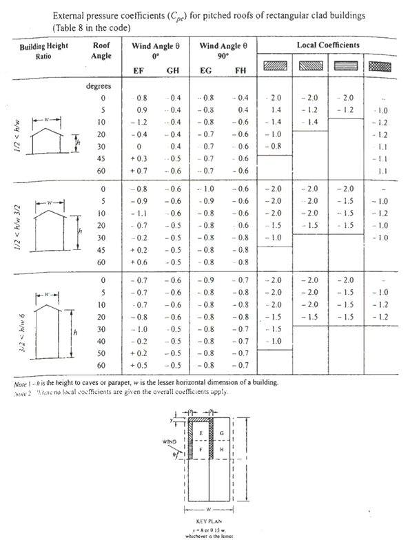

Key takeaways:
For the design of truss the above live load may be reduced to 2/3 radians
The purlins and sheets should be checked to support a concentrated load of 0.9 kN at the worst position.
References:
1. Design of Steel Structure, N Subramanian, Oxford University Press, New Delhi
2. Limit State Design in Structural Steel, M. R. Shiyekar, PHI, Delhi
3. Fundamentals of structural steel design, M L Gambhir, Tata McGraw Hill Education Private limited, New Delhi.
4. Structural Design in Steel, Sarwar Alam Raz, New Age International Publisher
5. Limit State Design of Steel Structure, V L Shah & Gore, Structures Publication, Pune
Unit - 1
Steel as a structural material
Firstly it’s useful to recognize what structural metal absolutely is and the way it's miles formed. Structural metal shapes are comprised of this type of metal that is formatted from a specific move section. Yet, on the identical time it follows exact requirements for mechanical homes and chemical composition. Structural metal is available in numerous shapes like L-beam, Z shape, HSS shape, L shape (angle), structural channel (C-beam, move section), T shaped, rail profile, bar, rod, plate and an open joist of internet metal.
Standard structural metallic varies in one-of-a-kind international locations with numerous specifications. For example, European I-beam is Euronorm 19-57, while structural metallic within side the USA is available in carbon, low alloy, corrosion resistant excessive power low alloy, quenched and tempered alloy metallic etc. Structural metallic is versatile, sturdy and durable, so it is infrequently sudden that it is able to be morphed into nearly any form primarily based totally on the development task at hand; it is able to be built nearly straight away the instant it's miles obtained at the constructing site. Structural metallic is hearth place-resistant in itself however hearth place safety strategies must be installed vicinity in case there may be a opportunity of it getting heated up to some extent wherein it begins off evolved to lose its sturdiness and power.
Corrosion must be avoided in terms of structural metallic, however tall homes are regarded to have withstood diverse types of adversities while constructed the usage of structural metallic. Steel creation is growing in reputation everywhere in the world, with each area benefitting from metallic for the duration of the years. Many of the quality architectural wonders were built through the usage of metallic, be it structural, carbon or rebar, together with The Empire State Building and the Sydney Harbor Bridge. More importantly, using metallic is useful in phrases of eco friendliness than different modes of creation, and because of this aspect alone, it's far given extra preference. Taking into attention the charge of marvelous constructions, metallic has proved favorable. With using metallic growing within side the creation industry, there may be absolute confidence that it's going to take over the whole creation discipline quickly within side the future.
Types of steel structures
1. Tower:
Towers may be self-supporting or cable-stayed. Towers are made of steel angles or tubes, bolted at site. Towers are of different types such as telephone tower, windmill tower, observation towers, lighting towers, power transmission towers etc. The function of tower is to provide support.
2. Roof truss:
A truss is a framed structure consisting of different members like tie, principal rafter, strut and slings; forming triangles i.e. a perfect frame. The steel roof trusses are used when
(1) Span is very large and the beam construction is not economical
(2) The building is in area of heavy rainfall.
Various types of trusses are
(i) Howe truss
(ii) Simple fink truss
(iii)Compound French truss
(vi) Simple tan truss
(v) Pratt truss
(vi) Compound fink truss
(vii) North-light truss etc.
3. Water tank:
They may be circular, rectangular or spherical. They may rest on the ground or be elevated. The function of water tank is to contain material.
4. Bridges:
The truss and plate-girder bridges are commonly used for small to moderate spans, cable-stayed and suspension bridges for long spans. Sometimes arch bridge and cantilever bridge are also used. Foot Bridge is very common in a railway station. The function of bridge is to provide runway.
5. Gantry girder:
The travelling overhead cranes are commonly used in workshops and factories. The function and gantry girder is to lift and move the heavy materials and machinery from one place to other.
6. Column:
These are the members that resist compressive components of loads in a truss, and bridge piers. In building structure loads and moments are transmitted to column through beams. Generally a compound column is used consisting of channels placed face to face or back to back. The two components must be tied together with the help of lacing or battening. The function of column is to give support.
Key takeaways:
- Towers may be self-supporting or cable-stayed. Towers are made of steel angles or tubes, bolted at site.
- These are the members that resist compressive components of loads in a truss, and bridge piers.
GRADES OF STRUCUTURAL STEEL-
The most common is Hot Rolled Medium and High Tensile Structural Steel conforming to IS: 2062.
This is used in steel structures in India.
You get these steels with varying chemical composition and mechanical properties and they are designated further by Grades.
The available grades are Grade 250 up to Grade 650.
The yield strengths start from 250MPa going up to 650 MPa.
The most commonly used grade is 250.
But for steel used as reinforcement in RCC construction the material grades are
IS 432 for mild steel medium tensile bars and
IS: 1786 for High strength deformed bars
Structural steel other than those specified under mild steel and high tensile steel conforming to wieldable quality may also be used provided that the permissible stresses and other design provisions are suitably modified and the steel is suitable for the type of fabrication adopted.
In this unit mild steel and high tensile steel are considered for the design.
The chemical composition of structural steel
Types of steel | Designation | IS Codes | C (Max) | Mn (Max) | S (max) | P (Max) | Si (Max) | Carbon equivalent |
Standard | Fe 410 A | 2062 | 0.23 | 1.5 | 0.050 | 0.050 | 0.4 | SK 0.42 |
Structure | Fe 410 B | 2062 | 0.22 | 1.5 | 0.045 | 0.045 | 0.4 | SK 0.41 |
Steel(IS 2062) | Fe 410 C | 2062 | 0.20 | 1.5 | 0.040 | 0.040 | 0.4 | K 0.39 |
Micro alloyed medium high strength steel | Fe 440 | 8500 | 0.20 | 1.5 | 0.050 | 0.050 | 0.45 | 0.40 |
Fe540 | 8500 | 0.20 | 1.5 | 0.045 | 0.045 | 0.45 | 0.44 | |
Fe 590 | 8500 | 0.20 | 1.5 | 0.045 | 0.045 | 0.45 | 0.48 |
Where,
Fe Stands for steel and the number after Fe is the tensile strength in N/mm^2 or MPa
K: killed steel
SK: Semi killed steel
C= Carbon
Mn = Manganese
S= Sulphur
P= phosphorus
Si= silicon
Structural Steel has been classified based on its ultimate or yield strength
e.g. Fe 410 Steel means minimum tensile strength of 410 N/mm^2. The mechanical properties of steel is largely depends on its chemical composition given below
Types of steel | Designation | UTS | Yield strength (MPa) Thickness (mm)/(<20 20-40>40) | Min. Percentage elongation gauge length = 5.65(A0)^2 | Charpy V notch impact energy (min) | ||
Standard | Fe 410 A | 410 | 250 | 240 | 230 | 23 | - |
Structure | Fe 410 B | 410 | 250 | 240 | 230 | 23 | 27 |
Steel (IS2062) | Fe 410 c | 410 | 250 | 240 | 230 | 23 | 27 |
Micro alloyed | Fe 440 B | 440 | 300 | 290 | 280 | 22 | 30 |
Medium/High | Fe 540 B | 540 | 410 | 390 | 380 | 20 | 25 |
Standard Steel | Fe 490 B | 490 | 350 | 330 | 320 | 22 | 25
|
Key takeaways:
Structural steel other than those specified under mild steel and high tensile steel conforming to weld able quality may also be used provided that the permissible stresses
There are various types of rolled steel sections which are listed below-
1- Rolled steel beam sections
2- Rolled steel channel sections
3- Rolled steel angle sections
4- Rolled steel Tee sections
5- Rolled steel bar
6- Rolled steel plates
7- Rolled steel flats
1- Rolled steel beam sections- they are various types which has various properties such as weight dimensions are given in steel table –
- Indian standard junior beams(ISJB)
- Indian standard light beams(ISLB)
- Indian standard medium beams(ISMB)
- Indian standard wide flange beams(ISWB)
- Indian standard heavy beams(ISHB)
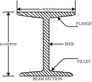
The above fig shows a typical beam, section. These section are designated by depth in mm and weight per metre run for example
ISMB500@0.852kg/m where 500 represents its depth in mm and 0.852 show uniformly distributed load per metre run.
2- Rolled steel channel sections-
They are classified into 4 groups-
- Indian standard junior channel (ISJC)
- Indian standard light channel (ISLC)
- Indian standard medium weight channel(ISMC)
- Indian standard special channel(ISSC)
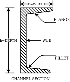
They are also designated by depth and weight for example ISMC250@0.450kN/m.
3- Rolled steel angle sections-
They are classified into 2 series-
- Indian standard equal angle (ISA)
- Indian standard unequal angle (ISA)
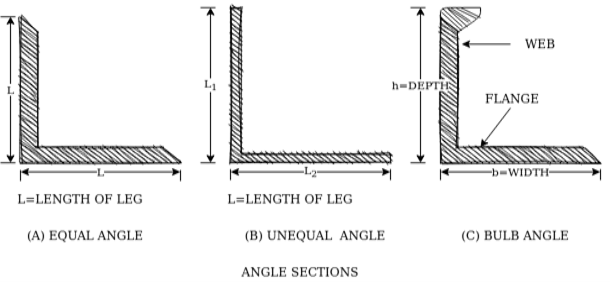
For equal angle section-
ISA150*150*12mm
For unequal angle section-
ISA90*75*8mm
4- Rolled steel Tee sections-
They are categorized into 5 series-
- Indian standard normal Tee bars (ISNT)
- Indian standard heavy flanged tee bars (ISHT)
- Indian standard light tee bars(ISLT)
- Indian standard junior tee bars (ISJT)
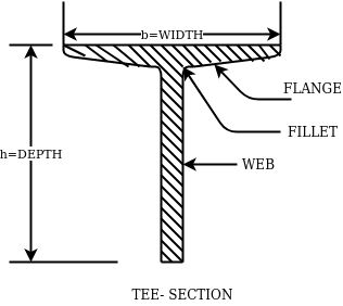
The rolled steel sections are designated by the series to which they belong followed by depth and weight per metre length.
Ex. ISNT60@53N/m
5- Rolled steel bars-
They are 2 types-
- Indian standard round bars (ISRO)
- Indian standard square bars (ISSQ)
Rolled steel bars are designated by ISRO followed by diameter in case of round bars and ISSQ followed by side width in case of square bars.
Example-ISRO10
ISSQ20
6- Rolled steel plates-
Rolled steel plates of following thicknesses are available such as 5,6,8,10,12,14,16,20,22,25,28,32,36,40,45,50,56,63,71, 80mm.they are rolled in widths 160,180,220,280,320 etc.
These plates are designated by ISPL followed by length,width, thickness. For example-ISPL2000*1000*6
7- Rolled steel flats-
They are designed by width followed by letters ISF and thickness.
For example- 80ISF 10 means 80mm wide flat for thickness 10mm.
Key takeaways:
Rolled steel bars are designated by ISRO followed by diameter in case of round bars and ISSQ followed by side width in case of square bars.
The latest version of the Code of Practice for general construction in steel IS: 800-2007 is based on Limit State Method of design. The design concept is totally changed in comparison to earlier code IS 800:1984 which is based on Elastic method.
IS: 800: 2007 – Code of Practice for general construction in Steel
This standard applies to general construction using hot rolled steel sections joined using riveting, bolting and welding. Specific provisions for bridges, chimneys, cranes, tanks, transmission line towers, bulk storage structures, tubular structures, cold formed light gauge steel sections, etc, are covered in separate standards.
This standard gives only general guidance as regards the various loads to be considered in design. For the actual loads and load combinations to be used, reference may be made to IS 875 for dead, live, snow and wind loads and to IS 1893 (Part 1) for earthquake loads.
IS: 808: 1989 – Dimensions for Hot Rolled Steel Beam, Column, Channel and Angle Sections.
IS:875 PART-I- DEAD LOADS - UNIT WEIGHTS OF BUILDING MATERIALS AND STORED MATERIALS.
IS:875 PART-II- code of practice for design loads (other than earthquake loads) for building and structures part 2 imposed loads
IS:875 PART-III- code of practice for design loads (other than earthquake loads) for building and structures part 3 wind loads.
IS 816–1969
Butt weld
This sort of weld is used while the contributors are in identical plane. Butt weld is likewise termed as groove weld. The butt weld is used to sign up for structural contributors wearing direct compression or tension. It is used to make tee-joint and butt-joint. The following forms of butt welds are in practice. These are named relying upon form of the grove made for welding.
Key takeaways:
The latest version of the Code of Practice for general construction in steel IS: 800-2007 is based on Limit State Method of design.
1. Plastic Analysis
Plastic layout is a way via way of means of which structural factors are decided on thinking about the system's ordinary final capacity. For safety, the implemented masses are in- creased via way of means of load elements dictated via way of means of suitable codes. This layout is primarily based totally at the yield belongings of the steel.
Plastic layout of metallic systems might also additionally count on distinctive ranges of complexity and sophistication. In this bankruptcy, techniques of evaluation and structural fashions primarily based totally on beam concept are presented. Plastic evaluation of systems may be performed with distinctive tiers of sophistication. The techniques of plastic evaluation may be primarily based totally at the static theorem or most principle, and the kinematic theorem or minimal principle. Plastic layout of metallic systems is frequently used withinside the layout of pitched-roof portal frames. The bankruptcy describes the verification techniques for contributors and additives that comprise capacity plastic hinges, being an crucial function of plastic layout. General standards for the verification of the stableness of contributors with plastic hinges, in addition to policies for bracings, are presented. Because of the complexity of such verifications and capacity lack of resistance and consequently economy, a not unusual place system is to save you out-of-aircraft buckling via way of means of the usage of good enough bracings.
The major distinction among elastic and plastic deign is the idea of the conduct of the shape. In elastic layout we anticipate that shape will fail if it reaches elastic restrict however in plastic evaluation we keep in mind that shape will fail while it reaches decrease yield point. In plastic layout we should keep in mind the deformed form of the shape and examine the secondary masses evolved because of the deformation. Here we additionally speak approximately the Shape Factors (S= Plastic Moment/ Yield Moment) for one of a kind form of sections like it is able to be one of a kind for square phase, I-Section, Circular Section etc. The essential situations of plastic evaluation are a) Equilibrium Condition: b) Yield Condition: At crumble, bending second at any phase ought to now no longer exceed the plastic second capability of the beam cross- phase. (Mp) c) Mechanism Condition: At the crumble condition, enough no of plastic hinges need to be evolved in order that a element or whole shape need to rework right into a mechanism, main to crumble. Theorem of Plastic Analysis: A) Static Theorem (Lower Bound Theorem) Static Theorem satisfies equilibrium and yield situations. It states that the crumble load observed on the premise of crumble B.M.D (wherein B.M at any phase is much less than or identical to Mp) will constantly be much less than or identical to crumble load. (P£ Pu). Static technique represents the decrease restrict of actual final load and has most aspect of safety. B) Kinematic Theorem (Upper Bound Theorem): Here equilibrium and mechanism situations are satisfied. It states that the crumble load observed via way of means of assuming the mechanism will constantly be more than or identical to the crumble load (P³ Pu). Where, P= Calculated crumble load, Pu = True crumble load
2. Plastic hinge formation
1. Plastic Theory
Plastic analysis will be introduced that behavior of steel beams & frames in the plastic range.
2. Terminology
Plasticity – It is defined as the state of permanent deformation without fracture in a material caused by the stresses which are greater than the yield stresses.
Plastic -Hinge – when the entire c/s of the beam becomes fully plastic on infinitely small increased in applied moment would cause large increases in curvature this effect is plastic hinge.
Plastic moment – The bending moment required to develop of plastic hinge is known as plastic moment. Denoted by Mp
Plastic collapse – It is also called collapse mechanism it is a condition of which the indefinite deflection occurs of construction load
Plastic collapse level – The load at which plastic collapse occurs is the plastic load it denoted by wu.
Load factor – It is the ratio of the collapse load to the working load.
It is assumption of plastic theory.
- The material is ductile of elastic plastic
- Strain hardening is neglected
- The deformations are small
- The beam is initially straight
- The beam is bending by pure bending the influence of axial force & shear on the plastic moment is neglected.
- The stress strain relation is ideal as bilinear in tension as well as company
- The loading is proportional.
Diagram
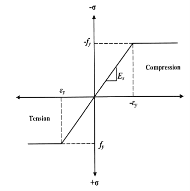
Consider a rectangular beam width of b and depth d subjected to steadily increasing load w over a simply supported span l
Stress stain diagrams shows elastic stress distribution for working and service load hence 
Where f= working stress
Further increases in load caused stress level fy at extreme fiber as shown in fig. This is the limit of elasticity
Therefore elasticity moment of resistance 

For rectangular section 
Further increases in load a does not produce increase in stress as fy remains constant as per idealize stress strain curve but strains increases thus stress is in the fiber immediately below the extreme fiber now reaches to fy
Yielding penetrated inside the fiber this is called elasto plastic range
Further increase in load causes yielding inside the cross section over the depth and the stress distribution is rectangular in both compression as well as tension this stage is known as fully plastic range and the moment at this stage is called plastic range
Moment at fully plastic stage is given by


For rectangular section C = total compressive force
= 
T= total tensile force= 
a = lever arm (y1+y2)
For rectangular section


Where Zp= plastic sectional modulus = 
Concurrently yielding also penetrated is adjoining cross section on either side
Here section
EE fully elastic range/stage
DD elasto plastic range /stage
CC fully plastic range/stage
When yielding of section takes place over entire depth
Section CC behaves similar to mechanical hinge called plastic hinge but at this plastic hinge moment is constant and it is denoted by Mp
Excessive rotation at C due to deformation of plastic hinge transform structure in to mechanism called as collapse mechanism. At this stage load w reaches to wp is called plastic collapse load


Now,
It is seen that rectangular section using equation

Thus the plastic stage rectangular section has 50% more strength compare to that of elastic stage.
Example
A S.S. Beam is determinate she. Formation of one hinge in the beam created collapse mechanism since, the maximum moment under the load the hinge will form at the place.
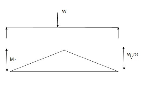

3. Shape factor
Shape factor:
It is ratio of plastic moment carrying capacity (Mp) to the yield moment (Me) of a section.
S = 
Shape factor –
It is defined as the of plastic moment of a section to the yield moment of the section
S = =  =
= 
Shape factor for Rectangular section.
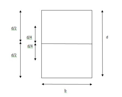
S = 
Zp = A/2 (y1 + y2)
= 
= bd2/4
Z = bd2/6
S = bd2/4 6/bd2 = 1.5
Shape factor of 1.5 Rectangular
Shape factor of Diamond section
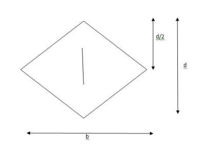
S = 
Zp = A/2 (y1 + y2)
= 
= bd2/6
Shape factor= 2 for Diamond
Shape factor for Triangle
Z = 
Diagram
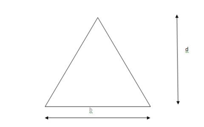
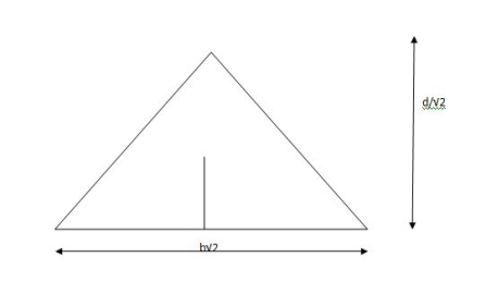
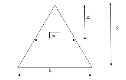
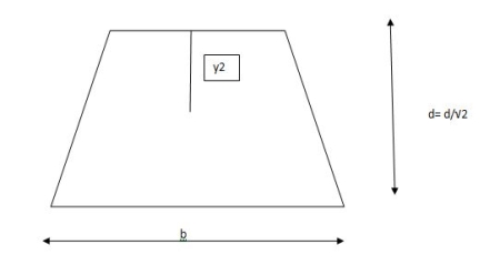
y2 = 
y2 = 0.1553
Zp = A/2 ( y1 + y2)
= 
Zp = 0.09775 bd2
S = Zp/Z = 2.346
Shape factor of triangle = 2.346
Shape factor for circular section
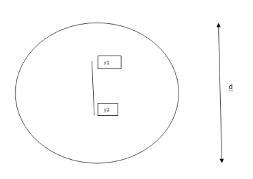
S = Zp/Z
Z= 1/Y = πD2/2 2/D = πD3/32
ZP = π/4 D2/2 [4r/3π + 4r/3π]
= π/4 D2/2 [2/3 D/3π + 2D/3π]
π/4 D2/2 [4D/3π] = D3/6
Collapse mechanism for beams
In the mechanism or kinematic approach of plastic analysis, numerous plastic failure mechanisms are evaluated. The plastic fall apart hundreds similar to numerous failure mechanisms are acquired with the aid of using equating the inner paintings on the plastic hinges to the 10W 10 W 6W 2T 3T 5T outside paintings with the aid of using hundreds in the course of the digital displacement. This calls for assessment of displacements and plastic hinge rotations. For gabled frames and different such frames, the kinematics of fall apart is somewhat complex. It is handy to apply the immediate centres of rotation of the inflexible elements of the body to assess displacements similar to one of a kind mechanisms. In this, homes of rotations of a inflexible frame in the course of an infinitesimally small perspective T
Fall apart*L/4. Then (0.50Mp+Mp)+ Pp*L/4, 2 will go together with 2, Mp=(1/6)*Pp*L. The Plastic Load or the fall apart load Pp=6*Mp/L.
Plastic analysis of determinate beam:
Examples
1. Determine load (Wu) using mechanism method of a simply supported beam subjected to point load at centre.

Solution:
- Number of plastic hinges required to collapse n= r+1 =1
- N=1
- n= N-r= 1
- Using virtual work principle


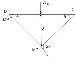
2. Determine collapse load (Wu) of a simply supported beam subjected to eccentric load.

Solution:
- Number of plastic hinge required to collapse n= r+1=1
- N=1
- N=n
- Using virtual work principle


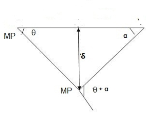
Using virtual work principle


3. Determine collapse load of a simply supported beam subjected to udl over span.

Solution:
- n= r+1=1
- N= 1
- N=n
- Virtual work principle

Average deformation
But 


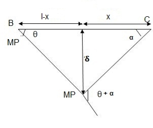
B. Plastic analysis of indeterminate beams
Examples:
1. Determine true collapse load of a propped cantilever beam subjected to load at centre.
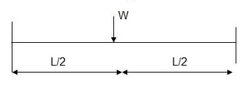
Solution:
- n=r+1 =2
- N=2
- N=n
- Using virtual work principle

But

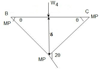
2. Determine true collapse load of a fixed beam subjected to udl

Solution:
- n=r+1= 3
- N=3
- N=n
- Using virtual work principle


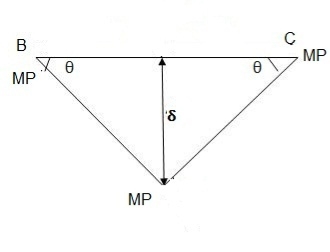
Where Wu= W.L = total UDL
(a) Tension members
Design strength due to gross section yielding (IS800-2007, Cl.6.2)
Steel members (plates, angles, etc) without bolt holes an sustain loads up to ultimate load without failure. However, the members will elongate considerably (10to15% of its original length) at this load and hence make the structure unserviceable. Hence the design strength Tdg is limited to the yielding of gross section which is given by,

Where
 = yield strength of the material in MPa
 = gross area of cross section in mm^2
 = 1.10= partial safety factor for failure at yielding
Design strength due to net section rupture
This occurs when the tension member is connected to the main or other members by bolts or weld. The holes made in members for bolt will reduce the cross section and hence net area will govern the failure in this case.
Design strength in tension of a plate

Step1-find the required gross area to carry the factored load considering strength in yielding –
Ag= 1.1 Tu/fy
Tu= factored tensile force
Step2-select suitable shape of the section depending upon the type of structure and the location of the member such that gross area is 25 to 40% more than Ag calculated.
Step3- determine the no. Of bolts or welding required.
Step4-find the strength considering –
1- Strength in yielding
2- Strength in rupture of critical section
3- Strength of block shear
If design is safe if Ag provided < Ag required
Step5- the strength obtained should be more than that factored tension
Step6- IS800:2007 also recommends the check for slenderness ratio of tension member as shown in table below-
Sr no. | Member | Max. Ur |
1. | A tension member in which a reversal of direct stress occurs due to load other than wind or seismic forces | 180 |
2. | A member normally acting as a tie in a roof truss or a bracing system not considered effective when subject to possible reversal of stress into compression resulting from the action of wind and earthquake forces. | 350 |
3. | Members always under tensions other than pretensioned members | 400 |
4. | Tension members, such as bracing, pretensioned to avoid sag , need not satisfy the maximum slenderness ratio limit | No limit |
Examples:
Q.1 Design bolted connection for single angle ISA 90 x 90x 6 mm @ 8.2 kg/m carrying factored axial tension 115 KN with 8 mm thick gusset plate. Use M16 bolt of property class 4.6
Solution:
Given
- Properties of cross section
ISA 90x90x6 mm @ 8.2 kg/m
Ultimate strength of bolt fub= 400 MPa
Ultimate strength of steel fu= 410 MPa


d = 16mm
d0= 18 mm
2. Design of bolted connection
- Shear strength of bolt


b. Bearing strength of bolt
a) 
b) 


Bolt value = least of V dsb and V dpb= 28.97 kN
Number of bolt required = 115/28.97 = 3.96 = 4 bolts
Q.2 A tie member of a truss 2ISA 65x65x6 @ 5.8 kg/m back to back on either side is welded to gusset plate. Design a weld to transmit a load equal to the full strength of the member.
Solution:
- Design tensile strength due to yielding of gross cross section

2. Design of welded connection
From tableIS 800-2007
Assume size of weld= 6 mm
By equating,


But

Taking moment about C.G


By using equation


b. Compression Member
Strength of compression member
The power of a compression member is described as its secure load sporting potential. The power of a centrally loaded immediately metal column relies upon at the powerful cross-sectional place, radius of gyration (viz., form of the cross-phase), the powerful duration, the importance and distribution of residual stresses, annealing, out of straightness and bloodless straightening.
The powerful cross-sectional place and the slenderness ratio of the compression contributors are the primary features, which have an effect on its power.
In case, the allowable stress is thought to differ parabolic ally with the slenderness ratio, it could be proved that the performance of a form of a compression member is associated with A/r2.
The performance of a form is described because the ratio of the allowable load for a given slenderness ratio to that for slenderness ratio identical to zero. The secure load sporting potential of compression member of recognized sectional place can be decided as follows:
Step1]
From the actual duration of the compression member and the guide situations of the member, that are recognized, the powerful duration of the member is computed.
Step 2]
From the radius of gyration approximately diverse axes of the phase given in phase tables, the minimum radius of gyration (rmin) is taken. rmin for a constructed-upphase is calculated.
Step 3]
The most slenderness ratio (l/ rmin) is decided for the compression member.
Step 4]
The allowable running stress (σac) within side the route of compression is found similar to the most slenderness ratio of the column from IS:800-1984.
Step 5]
The powerful sectional place (A) of the member is stated from structural metal phase tables. For the constructed-up contributors it could be calculated.
Step 6]
The secure load sporting potential of the member is decided as P= (σac. A), where P=secure load
Q.1 A single angle discontinuous strut ISA 150 mm x 150 mm x 12 mm (ISA 150 150, @0.272 kN/m) with single riveted connection is 3.5 m long. Calculate safe load carrying capacity of the section.
Solution:
Step 1: Properties of angle section
ISA 150 mm x 150 mm x 12 mm (ISA 150 150, @0.272 kN/m) is used as discontinuous strut. From the steel tables, the geometrical properties of the section are as follows:
Sectional area A = 3459 mm2
Radius of gyration rxx= ryy=149.3 mm
Radius of gyration ruu= 58.3 mm, rvv=29.3 mm
Step 2: Slenderness ratio,
Minimum radius of gyration rmin= 29.3 mm
Effective length of strut l= 3.5 m
Slenderness ratio of the strut
Step 3: Safe load
From IS:800-1984 for l/r=119.5 and the steel having yield stress, fy=260 N/mm2, allowable working stress in compression σac =64.45 N/mm2 (MPa)
For single angle discontinuous strut with single riveted connection, allowable working stress
0.80 σac = (0.80 x 64.45) = 51.56 N/mm2.
The safe load carrying capacity

Q.2 In case in Example 1, a discontinuous strut 150 x 150 x 15 angle section is used, calculate the safe load carrying capacity of the section.
Solution:
Step 1: Properties of angle section
Angle section 150 mm x 150 mm x 15 mm is used as discontinuous strut. From the steel tables, the geometrical properties of the section are as follows:
Sectional area A = 4300 mm2
Radius of gyration rxx= ryy=45.7 mm
Radius of gyration ruu= 57.6 mm, rvv=29.3 mm
Step 2: Slenderness ratio,
Minimum radius of gyration rmin= 29.3 mm
Effective length of strut l= 3.5 m
Slenderness ratio of the strut

Step 3: Safe load
From IS: 800-1984 for l/r=119.5 and the steel having yield stress, fy=260 N/mm2, allowable working stress in compression σac =64.45 N/mm2 (MPa)
For single angle discontinuous strut with single riveted connection, allowable working stress
0.80 σac = (0.80 x 64.45) = 51.56 N/mm2.
The safe load carrying capacity

Q.3 In Example 1, if single angle discontinuous strut is connected with more than two rivets in line along the angle at each end, calculate the safe load carrying capacity of the section.
Solution:
Step 1: Properties of angle section
Discontinuous strut ISA 150 mm x 150 mm x 12 mm (ISA 150 150, @0.272 kN/m) is used with double riveted connections. From the steel tables, the geometrical properties of the section are as follows:
Sectional area A = 3459 mm2
Radius of gyration rxx= ryy=149.3 mm
Radius of gyration ruu= 58.3 mm, rvv=29.3 mm
Length of strut between center to center of intersection L=3.50 m
Step 2: Slenderness ratio,
Minimum radius of gyration rmin= 29.3 mm
Effective length of discontinuous strut double riveted 0.85 x L= 0.85 x 3.5 = 2.975 m
Slenderness ratio of the strut

Step 3: Safe load
From IS:800-1984 for l/r=101.5 and the steel having yield stress, fy=260 N/mm2, allowable working stress in compression σac =71.65 N/mm2 (MPa)
Allowable working stress for discontinuous strut double riveted is not reduced.
The safe load carrying capacity 
Q.4 A double angle discontinuous strut ISA 125 mm x 95 mm x 10 mm (ISA 125 95, @0.165 kN/m) long legs back-to-back is connected to both the sides of a gusset plate 10 mm thick with 2 rivets. The length of strut between center to center of intersections is 4 m. Determine the safe load carrying capacity of the section.
Solution:
Step 1: Properties of angle section
The double angle discontinuous strut 2 ISA 125 mm x 95 mm x 10 mm (ISA 125 95, @0.165 kN/m) is shown in Fig. 11.4. Assume the tacking rivets are used along the length. From the steel tables, the geometrical properties of (two angle back-to-back) the sections are as follows:
Sectional area A = 4204 mm2
Radius of gyration rxx= 39.4 mm
Angles are 10 mm apart
Radius of gyration ryy= 40.1 mm
Length of strut between center to center of intersection L=4 m
Step 2: Slenderness ratio,
Minimum radius of gyration rmin= 39.4 mm
Effective length of discontinuous strut 0.85 x L= 0.85 x 4.0 = 3.40 m
Slenderness ratio of the strut

Step 3: Safe load
From IS:800-1984 for l/r=86.3 and the steel having yield stress, fy=260 N/mm2, allowable working stress in compression σac =95.96 N/mm2 (MPa)
The safe load carrying capacity

ROOF TRUSS-
The function of a truss is to transfer load from point of application to the supports as directly as possible. Thus for a concentrated load at the centerline of a span, a simple “A” frame is the most efficient. Like-wise, if only two equal and symmetrically placed concentrated loads are involved, a truss similar to the queen-post type is the most efficient. In both trusses, the load is transferred to the support directly through the sloping top-chord members without the need for web members.
[1] WALL PLATE / BEARIG
The first timber to be placed, it’s always horizontal and it’s placed at top of the external walls. Structural support of trusses (usually walls) normally with a timber wall plate.
[2] TYE BEAM / BOTTOM CHORD
Almost same as wall plate, but it’s not place on the wall it’s most time 1.2m apart, purposely use for the placement of ceiling. Horizontal along the spacing of the building. The tye beam is place after the wall plate.
[3] RAFTER / TOP CHORD
The rafter is in slant form always from one edge of the wall plate to another all meeting at the top of the key post. It’s also most time 1.2m apart.
[4] WEBS
Members that join the top and bottom chords to form a triangular pattern.
[5] PURLINS / BATTENS
It’s always been the last. It is put horizontally across the rafter. Which is most time 0.9m apart.
[6] APEX
Highest point where the sloping top chords meet.
[7] CANTILEVER
Part of structural member that extends beyond its support.
ROOF TRUSS TYPES-
King Post Truss
Central vertical post used in architectural, working in tension to support a beam below from a truss apex. This truss usually spans up to 8 meters, which makes it perfect for multiple types of houses, especially the smaller ones.
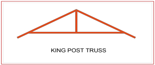
Queen Post Truss
A very reliable, simple and versatile type of roof truss where you can use at any given time. This kind of truss offers a span of around 10 meters, and has a simple design which makes it perfect for a wide range of establishments.
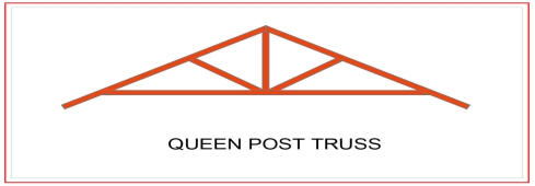
Howe Truss
A kind of truss having upper and lower members, a combination of steel and wood or both. One thing that makes this truss extraordinary is that it has a very wide span, as it can cover anything from 6-30 meters. This is very useful for a wide range of project types.
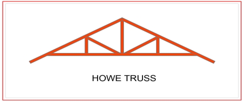
Pratt Truss
The prat truss is the most popular steel truss since it is very economical. It includes vertical and diagonal members that slope down towards the center (opposite of Howe Truss). Pratt truss can cover lengths ranging between 6-10 meters.
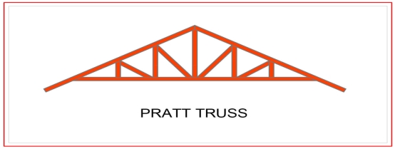
1. DEAD LOADS-
It includes the weight of sheeting purlins bracings, self weight and other loads suspended from trusses.
The unit weight of various material are given in IS875 part is. The following values may be noted-
GI sheets 85N/m2
AC sheets 130N/m2
In general the roof covering weight including lap, connectors etc may be taken as
1- 100-150 N/m2 for GI sheeting
2- 170-200N/m2 for A C sheeting
Weight of purlin should be added after designing purlin. Generally it works out 100-200N/m2 of plan area.
There are various formulae suggested to assume the self weight of the truss. These formulae economically used for a truss of span L
1- W=20+6.6L N/m2 for a LL of 2KN/m2
2- W=10(L/3 +5) s/4 N/m2 if LL is more than above value
Where s= spacing of truss
2. LIVE LOAD (IMPOSED LOAD)
IS875 part II makes the following provisions for live loads for the design of sheets and purlins.
Upto 10 degree slope -0.75kN/m2
For more than 10 degree slope -0.75-0.02(α-10)
Where α is the slope of sheeting
However a minimum of 0.4 Kn/m2 live load should be considered in any case.
For the design of truss the above live load may be reduced to 2/3 radians
The purlins and sheets should be checked to support a concentrated load of 0.9 kN at the worst position.
3. WIND LOAD-
IS875 part III gives the guidelines to determine wind forces on different components of buildings . It consists of the following steps
a- Determine basic wind speed
b- Obtain design wind speed
c- Calculate design wind pressure
d- Calculate wind pressure on roof
The steps are explained below-
a- Determine basic wind speed-(Vb)
For finding basic wind pressure in any place of india IS 875 par III divides the country into six zones as shown in fig. it is based on peak gust velocity averaged over a short time interval of about 3 seocnds studied over a period of 50 years . The value correspond to the speed at 10m height above ground level and in open terrain. For imp cities the basic wind pressure are given in the code. It may be observed that highest basic wind speed is 55m/s and lowest is 33 m/sec
b- Design wind speed (Vt)
The design wind speed of any site may be
Vt=k1 k2 k3 Vb
Where k1= risk coefficient
K2= terrain, height and structure
K3=topography factor
Risk coefficient (k1)-depending upon the importance of the building and basic wind speed IS875 has developed an equation to determine risk coefficient k1 for different types of buildings. These values shown in the table-
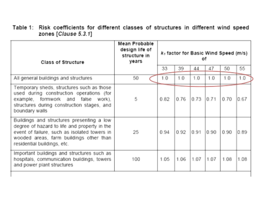
Terrain, height and structure size factor (k2)-
This coefficient depends upon terrain of the building site , height of the building and site of the building and class of building.
Buildings are classified into various classes-
Class A-buildings having maximum dimension less than 20m
Class B-Building having maximum dimension between 20 to 50m
Class C- building having maximum dimension greater than 50m
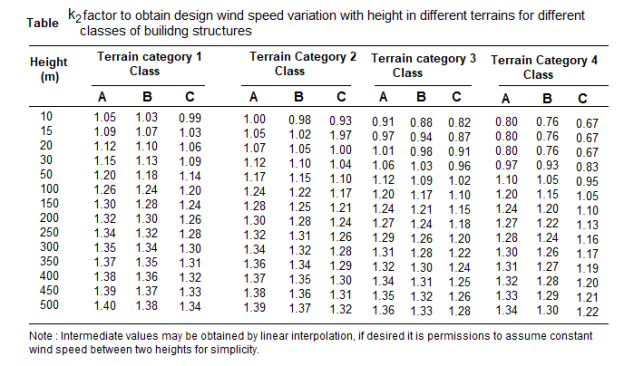
Topography factor (k3)-this factor is to account for the topographic features which influence design wind speed . Topographic features such as hills , valleys , cliffs etc
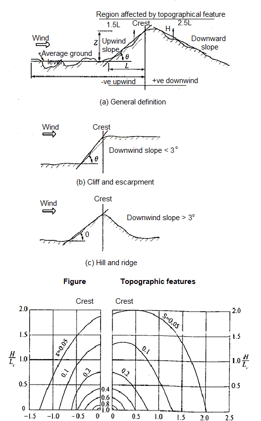
c- wind pressure-
The design wind pressure at any height above means ground level shall be calculated by following equation-
Pz=0.6 Vz2
Where
Pz=design wind pressure in N/m2at height z
Vz= design wind velocity in m/sec at height z
d- wind pressure on roof-
For calculating the wind load on individual structural elements it is essential to take into account of pressure difference between opposite faces of such elements. If internal as well as external pressure are found then wind load acting in a direction normal to the individual structural element is-
F=(Cpe - Cpi) A pd
Where Cpe= external pressure coefficient
Cpi= internal pressure coefficient
A= surface area
Pd=design wind pressure (N/m2)
Buildings with Cpi
Low permeability (less than 5% openings in wall area) ± 0.2
Medium permeability (5 – 20 % opening in wall) ± 0.5
Large openings (openings > 20% in wall) ±0.7
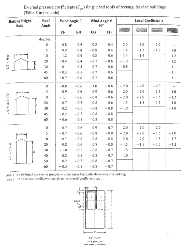

Key takeaways:
For the design of truss the above live load may be reduced to 2/3 radians
The purlins and sheets should be checked to support a concentrated load of 0.9 kN at the worst position.
References:
1. Design of Steel Structure, N Subramanian, Oxford University Press, New Delhi
2. Limit State Design in Structural Steel, M. R. Shiyekar, PHI, Delhi
3. Fundamentals of structural steel design, M L Gambhir, Tata McGraw Hill Education Private limited, New Delhi.
4. Structural Design in Steel, Sarwar Alam Raz, New Age International Publisher
5. Limit State Design of Steel Structure, V L Shah & Gore, Structures Publication, Pune
Unit - 1
Steel as a structural material
Firstly it’s useful to recognize what structural metal absolutely is and the way it's miles formed. Structural metal shapes are comprised of this type of metal that is formatted from a specific move section. Yet, on the identical time it follows exact requirements for mechanical homes and chemical composition. Structural metal is available in numerous shapes like L-beam, Z shape, HSS shape, L shape (angle), structural channel (C-beam, move section), T shaped, rail profile, bar, rod, plate and an open joist of internet metal.
Standard structural metallic varies in one-of-a-kind international locations with numerous specifications. For example, European I-beam is Euronorm 19-57, while structural metallic within side the USA is available in carbon, low alloy, corrosion resistant excessive power low alloy, quenched and tempered alloy metallic etc. Structural metallic is versatile, sturdy and durable, so it is infrequently sudden that it is able to be morphed into nearly any form primarily based totally on the development task at hand; it is able to be built nearly straight away the instant it's miles obtained at the constructing site. Structural metallic is hearth place-resistant in itself however hearth place safety strategies must be installed vicinity in case there may be a opportunity of it getting heated up to some extent wherein it begins off evolved to lose its sturdiness and power.
Corrosion must be avoided in terms of structural metallic, however tall homes are regarded to have withstood diverse types of adversities while constructed the usage of structural metallic. Steel creation is growing in reputation everywhere in the world, with each area benefitting from metallic for the duration of the years. Many of the quality architectural wonders were built through the usage of metallic, be it structural, carbon or rebar, together with The Empire State Building and the Sydney Harbor Bridge. More importantly, using metallic is useful in phrases of eco friendliness than different modes of creation, and because of this aspect alone, it's far given extra preference. Taking into attention the charge of marvelous constructions, metallic has proved favorable. With using metallic growing within side the creation industry, there may be absolute confidence that it's going to take over the whole creation discipline quickly within side the future.
Types of steel structures
1. Tower:
Towers may be self-supporting or cable-stayed. Towers are made of steel angles or tubes, bolted at site. Towers are of different types such as telephone tower, windmill tower, observation towers, lighting towers, power transmission towers etc. The function of tower is to provide support.
2. Roof truss:
A truss is a framed structure consisting of different members like tie, principal rafter, strut and slings; forming triangles i.e. a perfect frame. The steel roof trusses are used when
(1) Span is very large and the beam construction is not economical
(2) The building is in area of heavy rainfall.
Various types of trusses are
(i) Howe truss
(ii) Simple fink truss
(iii)Compound French truss
(vi) Simple tan truss
(v) Pratt truss
(vi) Compound fink truss
(vii) North-light truss etc.
3. Water tank:
They may be circular, rectangular or spherical. They may rest on the ground or be elevated. The function of water tank is to contain material.
4. Bridges:
The truss and plate-girder bridges are commonly used for small to moderate spans, cable-stayed and suspension bridges for long spans. Sometimes arch bridge and cantilever bridge are also used. Foot Bridge is very common in a railway station. The function of bridge is to provide runway.
5. Gantry girder:
The travelling overhead cranes are commonly used in workshops and factories. The function and gantry girder is to lift and move the heavy materials and machinery from one place to other.
6. Column:
These are the members that resist compressive components of loads in a truss, and bridge piers. In building structure loads and moments are transmitted to column through beams. Generally a compound column is used consisting of channels placed face to face or back to back. The two components must be tied together with the help of lacing or battening. The function of column is to give support.
Key takeaways:
- Towers may be self-supporting or cable-stayed. Towers are made of steel angles or tubes, bolted at site.
- These are the members that resist compressive components of loads in a truss, and bridge piers.
GRADES OF STRUCUTURAL STEEL-
The most common is Hot Rolled Medium and High Tensile Structural Steel conforming to IS: 2062.
This is used in steel structures in India.
You get these steels with varying chemical composition and mechanical properties and they are designated further by Grades.
The available grades are Grade 250 up to Grade 650.
The yield strengths start from 250MPa going up to 650 MPa.
The most commonly used grade is 250.
But for steel used as reinforcement in RCC construction the material grades are
IS 432 for mild steel medium tensile bars and
IS: 1786 for High strength deformed bars
Structural steel other than those specified under mild steel and high tensile steel conforming to wieldable quality may also be used provided that the permissible stresses and other design provisions are suitably modified and the steel is suitable for the type of fabrication adopted.
In this unit mild steel and high tensile steel are considered for the design.
The chemical composition of structural steel
Types of steel | Designation | IS Codes | C (Max) | Mn (Max) | S (max) | P (Max) | Si (Max) | Carbon equivalent |
Standard | Fe 410 A | 2062 | 0.23 | 1.5 | 0.050 | 0.050 | 0.4 | SK 0.42 |
Structure | Fe 410 B | 2062 | 0.22 | 1.5 | 0.045 | 0.045 | 0.4 | SK 0.41 |
Steel(IS 2062) | Fe 410 C | 2062 | 0.20 | 1.5 | 0.040 | 0.040 | 0.4 | K 0.39 |
Micro alloyed medium high strength steel | Fe 440 | 8500 | 0.20 | 1.5 | 0.050 | 0.050 | 0.45 | 0.40 |
Fe540 | 8500 | 0.20 | 1.5 | 0.045 | 0.045 | 0.45 | 0.44 | |
Fe 590 | 8500 | 0.20 | 1.5 | 0.045 | 0.045 | 0.45 | 0.48 |
Where,
Fe Stands for steel and the number after Fe is the tensile strength in N/mm^2 or MPa
K: killed steel
SK: Semi killed steel
C= Carbon
Mn = Manganese
S= Sulphur
P= phosphorus
Si= silicon
Structural Steel has been classified based on its ultimate or yield strength
e.g. Fe 410 Steel means minimum tensile strength of 410 N/mm^2. The mechanical properties of steel is largely depends on its chemical composition given below
Types of steel | Designation | UTS | Yield strength (MPa) Thickness (mm)/(<20 20-40>40) | Min. Percentage elongation gauge length = 5.65(A0)^2 | Charpy V notch impact energy (min) | ||
Standard | Fe 410 A | 410 | 250 | 240 | 230 | 23 | - |
Structure | Fe 410 B | 410 | 250 | 240 | 230 | 23 | 27 |
Steel (IS2062) | Fe 410 c | 410 | 250 | 240 | 230 | 23 | 27 |
Micro alloyed | Fe 440 B | 440 | 300 | 290 | 280 | 22 | 30 |
Medium/High | Fe 540 B | 540 | 410 | 390 | 380 | 20 | 25 |
Standard Steel | Fe 490 B | 490 | 350 | 330 | 320 | 22 | 25
|
Key takeaways:
Structural steel other than those specified under mild steel and high tensile steel conforming to weld able quality may also be used provided that the permissible stresses
There are various types of rolled steel sections which are listed below-
1- Rolled steel beam sections
2- Rolled steel channel sections
3- Rolled steel angle sections
4- Rolled steel Tee sections
5- Rolled steel bar
6- Rolled steel plates
7- Rolled steel flats
1- Rolled steel beam sections- they are various types which has various properties such as weight dimensions are given in steel table –
- Indian standard junior beams(ISJB)
- Indian standard light beams(ISLB)
- Indian standard medium beams(ISMB)
- Indian standard wide flange beams(ISWB)
- Indian standard heavy beams(ISHB)
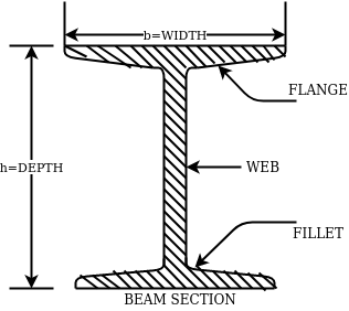
The above fig shows a typical beam, section. These section are designated by depth in mm and weight per metre run for example
ISMB500@0.852kg/m where 500 represents its depth in mm and 0.852 show uniformly distributed load per metre run.
2- Rolled steel channel sections-
They are classified into 4 groups-
- Indian standard junior channel (ISJC)
- Indian standard light channel (ISLC)
- Indian standard medium weight channel(ISMC)
- Indian standard special channel(ISSC)
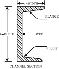
They are also designated by depth and weight for example ISMC250@0.450kN/m.
3- Rolled steel angle sections-
They are classified into 2 series-
- Indian standard equal angle (ISA)
- Indian standard unequal angle (ISA)
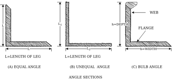
For equal angle section-
ISA150*150*12mm
For unequal angle section-
ISA90*75*8mm
4- Rolled steel Tee sections-
They are categorized into 5 series-
- Indian standard normal Tee bars (ISNT)
- Indian standard heavy flanged tee bars (ISHT)
- Indian standard light tee bars(ISLT)
- Indian standard junior tee bars (ISJT)
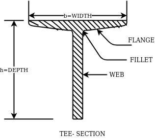
The rolled steel sections are designated by the series to which they belong followed by depth and weight per metre length.
Ex. ISNT60@53N/m
5- Rolled steel bars-
They are 2 types-
- Indian standard round bars (ISRO)
- Indian standard square bars (ISSQ)
Rolled steel bars are designated by ISRO followed by diameter in case of round bars and ISSQ followed by side width in case of square bars.
Example-ISRO10
ISSQ20
6- Rolled steel plates-
Rolled steel plates of following thicknesses are available such as 5,6,8,10,12,14,16,20,22,25,28,32,36,40,45,50,56,63,71, 80mm.they are rolled in widths 160,180,220,280,320 etc.
These plates are designated by ISPL followed by length,width, thickness. For example-ISPL2000*1000*6
7- Rolled steel flats-
They are designed by width followed by letters ISF and thickness.
For example- 80ISF 10 means 80mm wide flat for thickness 10mm.
Key takeaways:
Rolled steel bars are designated by ISRO followed by diameter in case of round bars and ISSQ followed by side width in case of square bars.
The latest version of the Code of Practice for general construction in steel IS: 800-2007 is based on Limit State Method of design. The design concept is totally changed in comparison to earlier code IS 800:1984 which is based on Elastic method.
IS: 800: 2007 – Code of Practice for general construction in Steel
This standard applies to general construction using hot rolled steel sections joined using riveting, bolting and welding. Specific provisions for bridges, chimneys, cranes, tanks, transmission line towers, bulk storage structures, tubular structures, cold formed light gauge steel sections, etc, are covered in separate standards.
This standard gives only general guidance as regards the various loads to be considered in design. For the actual loads and load combinations to be used, reference may be made to IS 875 for dead, live, snow and wind loads and to IS 1893 (Part 1) for earthquake loads.
IS: 808: 1989 – Dimensions for Hot Rolled Steel Beam, Column, Channel and Angle Sections.
IS:875 PART-I- DEAD LOADS - UNIT WEIGHTS OF BUILDING MATERIALS AND STORED MATERIALS.
IS:875 PART-II- code of practice for design loads (other than earthquake loads) for building and structures part 2 imposed loads
IS:875 PART-III- code of practice for design loads (other than earthquake loads) for building and structures part 3 wind loads.
IS 816–1969
Butt weld
This sort of weld is used while the contributors are in identical plane. Butt weld is likewise termed as groove weld. The butt weld is used to sign up for structural contributors wearing direct compression or tension. It is used to make tee-joint and butt-joint. The following forms of butt welds are in practice. These are named relying upon form of the grove made for welding.
Key takeaways:
The latest version of the Code of Practice for general construction in steel IS: 800-2007 is based on Limit State Method of design.
1. Plastic Analysis
Plastic layout is a way via way of means of which structural factors are decided on thinking about the system's ordinary final capacity. For safety, the implemented masses are in- creased via way of means of load elements dictated via way of means of suitable codes. This layout is primarily based totally at the yield belongings of the steel.
Plastic layout of metallic systems might also additionally count on distinctive ranges of complexity and sophistication. In this bankruptcy, techniques of evaluation and structural fashions primarily based totally on beam concept are presented. Plastic evaluation of systems may be performed with distinctive tiers of sophistication. The techniques of plastic evaluation may be primarily based totally at the static theorem or most principle, and the kinematic theorem or minimal principle. Plastic layout of metallic systems is frequently used withinside the layout of pitched-roof portal frames. The bankruptcy describes the verification techniques for contributors and additives that comprise capacity plastic hinges, being an crucial function of plastic layout. General standards for the verification of the stableness of contributors with plastic hinges, in addition to policies for bracings, are presented. Because of the complexity of such verifications and capacity lack of resistance and consequently economy, a not unusual place system is to save you out-of-aircraft buckling via way of means of the usage of good enough bracings.
The major distinction among elastic and plastic deign is the idea of the conduct of the shape. In elastic layout we anticipate that shape will fail if it reaches elastic restrict however in plastic evaluation we keep in mind that shape will fail while it reaches decrease yield point. In plastic layout we should keep in mind the deformed form of the shape and examine the secondary masses evolved because of the deformation. Here we additionally speak approximately the Shape Factors (S= Plastic Moment/ Yield Moment) for one of a kind form of sections like it is able to be one of a kind for square phase, I-Section, Circular Section etc. The essential situations of plastic evaluation are a) Equilibrium Condition: b) Yield Condition: At crumble, bending second at any phase ought to now no longer exceed the plastic second capability of the beam cross- phase. (Mp) c) Mechanism Condition: At the crumble condition, enough no of plastic hinges need to be evolved in order that a element or whole shape need to rework right into a mechanism, main to crumble. Theorem of Plastic Analysis: A) Static Theorem (Lower Bound Theorem) Static Theorem satisfies equilibrium and yield situations. It states that the crumble load observed on the premise of crumble B.M.D (wherein B.M at any phase is much less than or identical to Mp) will constantly be much less than or identical to crumble load. (P£ Pu). Static technique represents the decrease restrict of actual final load and has most aspect of safety. B) Kinematic Theorem (Upper Bound Theorem): Here equilibrium and mechanism situations are satisfied. It states that the crumble load observed via way of means of assuming the mechanism will constantly be more than or identical to the crumble load (P³ Pu). Where, P= Calculated crumble load, Pu = True crumble load
2. Plastic hinge formation
1. Plastic Theory
Plastic analysis will be introduced that behavior of steel beams & frames in the plastic range.
2. Terminology
Plasticity – It is defined as the state of permanent deformation without fracture in a material caused by the stresses which are greater than the yield stresses.
Plastic -Hinge – when the entire c/s of the beam becomes fully plastic on infinitely small increased in applied moment would cause large increases in curvature this effect is plastic hinge.
Plastic moment – The bending moment required to develop of plastic hinge is known as plastic moment. Denoted by Mp
Plastic collapse – It is also called collapse mechanism it is a condition of which the indefinite deflection occurs of construction load
Plastic collapse level – The load at which plastic collapse occurs is the plastic load it denoted by wu.
Load factor – It is the ratio of the collapse load to the working load.
It is assumption of plastic theory.
- The material is ductile of elastic plastic
- Strain hardening is neglected
- The deformations are small
- The beam is initially straight
- The beam is bending by pure bending the influence of axial force & shear on the plastic moment is neglected.
- The stress strain relation is ideal as bilinear in tension as well as company
- The loading is proportional.
Diagram
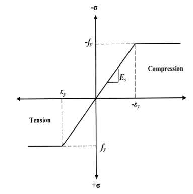
Consider a rectangular beam width of b and depth d subjected to steadily increasing load w over a simply supported span l
Stress stain diagrams shows elastic stress distribution for working and service load hence 
Where f= working stress
Further increases in load caused stress level fy at extreme fiber as shown in fig. This is the limit of elasticity
Therefore elasticity moment of resistance 

For rectangular section 
Further increases in load a does not produce increase in stress as fy remains constant as per idealize stress strain curve but strains increases thus stress is in the fiber immediately below the extreme fiber now reaches to fy
Yielding penetrated inside the fiber this is called elasto plastic range
Further increase in load causes yielding inside the cross section over the depth and the stress distribution is rectangular in both compression as well as tension this stage is known as fully plastic range and the moment at this stage is called plastic range
Moment at fully plastic stage is given by


For rectangular section C = total compressive force
= 
T= total tensile force= 
a = lever arm (y1+y2)
For rectangular section


Where Zp= plastic sectional modulus = 
Concurrently yielding also penetrated is adjoining cross section on either side
Here section
EE fully elastic range/stage
DD elasto plastic range /stage
CC fully plastic range/stage
When yielding of section takes place over entire depth
Section CC behaves similar to mechanical hinge called plastic hinge but at this plastic hinge moment is constant and it is denoted by Mp
Excessive rotation at C due to deformation of plastic hinge transform structure in to mechanism called as collapse mechanism. At this stage load w reaches to wp is called plastic collapse load


Now,
It is seen that rectangular section using equation

Thus the plastic stage rectangular section has 50% more strength compare to that of elastic stage.
Example
A S.S. Beam is determinate she. Formation of one hinge in the beam created collapse mechanism since, the maximum moment under the load the hinge will form at the place.
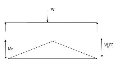

3. Shape factor
Shape factor:
It is ratio of plastic moment carrying capacity (Mp) to the yield moment (Me) of a section.
S = 
Shape factor –
It is defined as the of plastic moment of a section to the yield moment of the section
S = =  =
= 
Shape factor for Rectangular section.
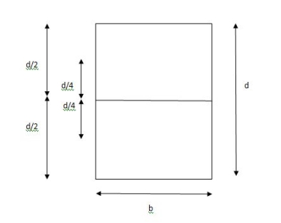
S = 
Zp = A/2 (y1 + y2)
= 
= bd2/4
Z = bd2/6
S = bd2/4 6/bd2 = 1.5
Shape factor of 1.5 Rectangular
Shape factor of Diamond section
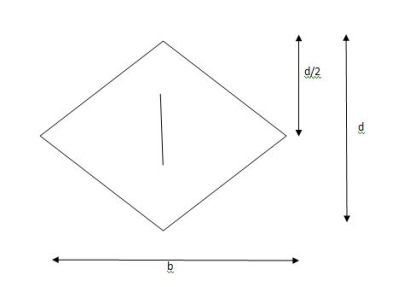
S = 
Zp = A/2 (y1 + y2)
= 
= bd2/6
Shape factor= 2 for Diamond
Shape factor for Triangle
Z = 
Diagram
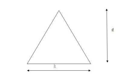
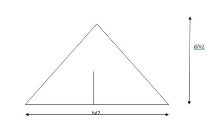
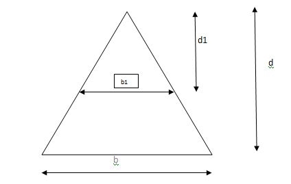
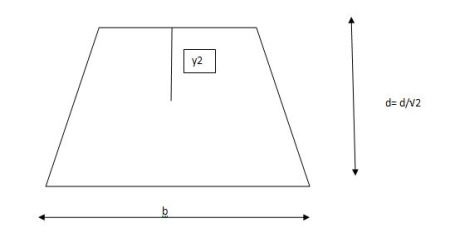
y2 = 
y2 = 0.1553
Zp = A/2 ( y1 + y2)
= 
Zp = 0.09775 bd2
S = Zp/Z = 2.346
Shape factor of triangle = 2.346
Shape factor for circular section
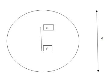
S = Zp/Z
Z= 1/Y = πD2/2 2/D = πD3/32
ZP = π/4 D2/2 [4r/3π + 4r/3π]
= π/4 D2/2 [2/3 D/3π + 2D/3π]
π/4 D2/2 [4D/3π] = D3/6
Collapse mechanism for beams
In the mechanism or kinematic approach of plastic analysis, numerous plastic failure mechanisms are evaluated. The plastic fall apart hundreds similar to numerous failure mechanisms are acquired with the aid of using equating the inner paintings on the plastic hinges to the 10W 10 W 6W 2T 3T 5T outside paintings with the aid of using hundreds in the course of the digital displacement. This calls for assessment of displacements and plastic hinge rotations. For gabled frames and different such frames, the kinematics of fall apart is somewhat complex. It is handy to apply the immediate centres of rotation of the inflexible elements of the body to assess displacements similar to one of a kind mechanisms. In this, homes of rotations of a inflexible frame in the course of an infinitesimally small perspective T
Fall apart*L/4. Then (0.50Mp+Mp)+ Pp*L/4, 2 will go together with 2, Mp=(1/6)*Pp*L. The Plastic Load or the fall apart load Pp=6*Mp/L.
Plastic analysis of determinate beam:
Examples
1. Determine load (Wu) using mechanism method of a simply supported beam subjected to point load at centre.

Solution:
- Number of plastic hinges required to collapse n= r+1 =1
- N=1
- n= N-r= 1
- Using virtual work principle


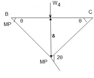
2. Determine collapse load (Wu) of a simply supported beam subjected to eccentric load.

Solution:
- Number of plastic hinge required to collapse n= r+1=1
- N=1
- N=n
- Using virtual work principle


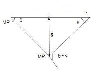
Using virtual work principle


3. Determine collapse load of a simply supported beam subjected to udl over span.

Solution:
- n= r+1=1
- N= 1
- N=n
- Virtual work principle

Average deformation
But 


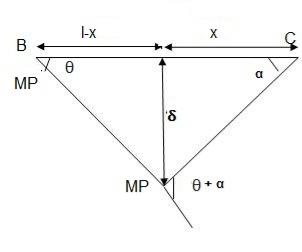
B. Plastic analysis of indeterminate beams
Examples:
1. Determine true collapse load of a propped cantilever beam subjected to load at centre.
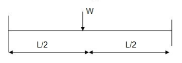
Solution:
- n=r+1 =2
- N=2
- N=n
- Using virtual work principle

But

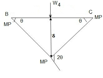
2. Determine true collapse load of a fixed beam subjected to udl

Solution:
- n=r+1= 3
- N=3
- N=n
- Using virtual work principle


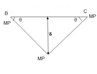
Where Wu= W.L = total UDL
(a) Tension members
Design strength due to gross section yielding (IS800-2007, Cl.6.2)
Steel members (plates, angles, etc) without bolt holes an sustain loads up to ultimate load without failure. However, the members will elongate considerably (10to15% of its original length) at this load and hence make the structure unserviceable. Hence the design strength Tdg is limited to the yielding of gross section which is given by,

Where
 = yield strength of the material in MPa
 = gross area of cross section in mm^2
 = 1.10= partial safety factor for failure at yielding
Design strength due to net section rupture
This occurs when the tension member is connected to the main or other members by bolts or weld. The holes made in members for bolt will reduce the cross section and hence net area will govern the failure in this case.
Design strength in tension of a plate

Step1-find the required gross area to carry the factored load considering strength in yielding –
Ag= 1.1 Tu/fy
Tu= factored tensile force
Step2-select suitable shape of the section depending upon the type of structure and the location of the member such that gross area is 25 to 40% more than Ag calculated.
Step3- determine the no. Of bolts or welding required.
Step4-find the strength considering –
1- Strength in yielding
2- Strength in rupture of critical section
3- Strength of block shear
If design is safe if Ag provided < Ag required
Step5- the strength obtained should be more than that factored tension
Step6- IS800:2007 also recommends the check for slenderness ratio of tension member as shown in table below-
Sr no. | Member | Max. Ur |
1. | A tension member in which a reversal of direct stress occurs due to load other than wind or seismic forces | 180 |
2. | A member normally acting as a tie in a roof truss or a bracing system not considered effective when subject to possible reversal of stress into compression resulting from the action of wind and earthquake forces. | 350 |
3. | Members always under tensions other than pretensioned members | 400 |
4. | Tension members, such as bracing, pretensioned to avoid sag , need not satisfy the maximum slenderness ratio limit | No limit |
Examples:
Q.1 Design bolted connection for single angle ISA 90 x 90x 6 mm @ 8.2 kg/m carrying factored axial tension 115 KN with 8 mm thick gusset plate. Use M16 bolt of property class 4.6
Solution:
Given
- Properties of cross section
ISA 90x90x6 mm @ 8.2 kg/m
Ultimate strength of bolt fub= 400 MPa
Ultimate strength of steel fu= 410 MPa


d = 16mm
d0= 18 mm
2. Design of bolted connection
- Shear strength of bolt


b. Bearing strength of bolt
a) 
b) 


Bolt value = least of V dsb and V dpb= 28.97 kN
Number of bolt required = 115/28.97 = 3.96 = 4 bolts
Q.2 A tie member of a truss 2ISA 65x65x6 @ 5.8 kg/m back to back on either side is welded to gusset plate. Design a weld to transmit a load equal to the full strength of the member.
Solution:
- Design tensile strength due to yielding of gross cross section

2. Design of welded connection
From tableIS 800-2007
Assume size of weld= 6 mm
By equating,


But

Taking moment about C.G


By using equation


b. Compression Member
Strength of compression member
The power of a compression member is described as its secure load sporting potential. The power of a centrally loaded immediately metal column relies upon at the powerful cross-sectional place, radius of gyration (viz., form of the cross-phase), the powerful duration, the importance and distribution of residual stresses, annealing, out of straightness and bloodless straightening.
The powerful cross-sectional place and the slenderness ratio of the compression contributors are the primary features, which have an effect on its power.
In case, the allowable stress is thought to differ parabolic ally with the slenderness ratio, it could be proved that the performance of a form of a compression member is associated with A/r2.
The performance of a form is described because the ratio of the allowable load for a given slenderness ratio to that for slenderness ratio identical to zero. The secure load sporting potential of compression member of recognized sectional place can be decided as follows:
Step1]
From the actual duration of the compression member and the guide situations of the member, that are recognized, the powerful duration of the member is computed.
Step 2]
From the radius of gyration approximately diverse axes of the phase given in phase tables, the minimum radius of gyration (rmin) is taken. rmin for a constructed-upphase is calculated.
Step 3]
The most slenderness ratio (l/ rmin) is decided for the compression member.
Step 4]
The allowable running stress (σac) within side the route of compression is found similar to the most slenderness ratio of the column from IS:800-1984.
Step 5]
The powerful sectional place (A) of the member is stated from structural metal phase tables. For the constructed-up contributors it could be calculated.
Step 6]
The secure load sporting potential of the member is decided as P= (σac. A), where P=secure load
Q.1 A single angle discontinuous strut ISA 150 mm x 150 mm x 12 mm (ISA 150 150, @0.272 kN/m) with single riveted connection is 3.5 m long. Calculate safe load carrying capacity of the section.
Solution:
Step 1: Properties of angle section
ISA 150 mm x 150 mm x 12 mm (ISA 150 150, @0.272 kN/m) is used as discontinuous strut. From the steel tables, the geometrical properties of the section are as follows:
Sectional area A = 3459 mm2
Radius of gyration rxx= ryy=149.3 mm
Radius of gyration ruu= 58.3 mm, rvv=29.3 mm
Step 2: Slenderness ratio,
Minimum radius of gyration rmin= 29.3 mm
Effective length of strut l= 3.5 m
Slenderness ratio of the strut
Step 3: Safe load
From IS:800-1984 for l/r=119.5 and the steel having yield stress, fy=260 N/mm2, allowable working stress in compression σac =64.45 N/mm2 (MPa)
For single angle discontinuous strut with single riveted connection, allowable working stress
0.80 σac = (0.80 x 64.45) = 51.56 N/mm2.
The safe load carrying capacity

Q.2 In case in Example 1, a discontinuous strut 150 x 150 x 15 angle section is used, calculate the safe load carrying capacity of the section.
Solution:
Step 1: Properties of angle section
Angle section 150 mm x 150 mm x 15 mm is used as discontinuous strut. From the steel tables, the geometrical properties of the section are as follows:
Sectional area A = 4300 mm2
Radius of gyration rxx= ryy=45.7 mm
Radius of gyration ruu= 57.6 mm, rvv=29.3 mm
Step 2: Slenderness ratio,
Minimum radius of gyration rmin= 29.3 mm
Effective length of strut l= 3.5 m
Slenderness ratio of the strut

Step 3: Safe load
From IS: 800-1984 for l/r=119.5 and the steel having yield stress, fy=260 N/mm2, allowable working stress in compression σac =64.45 N/mm2 (MPa)
For single angle discontinuous strut with single riveted connection, allowable working stress
0.80 σac = (0.80 x 64.45) = 51.56 N/mm2.
The safe load carrying capacity

Q.3 In Example 1, if single angle discontinuous strut is connected with more than two rivets in line along the angle at each end, calculate the safe load carrying capacity of the section.
Solution:
Step 1: Properties of angle section
Discontinuous strut ISA 150 mm x 150 mm x 12 mm (ISA 150 150, @0.272 kN/m) is used with double riveted connections. From the steel tables, the geometrical properties of the section are as follows:
Sectional area A = 3459 mm2
Radius of gyration rxx= ryy=149.3 mm
Radius of gyration ruu= 58.3 mm, rvv=29.3 mm
Length of strut between center to center of intersection L=3.50 m
Step 2: Slenderness ratio,
Minimum radius of gyration rmin= 29.3 mm
Effective length of discontinuous strut double riveted 0.85 x L= 0.85 x 3.5 = 2.975 m
Slenderness ratio of the strut

Step 3: Safe load
From IS:800-1984 for l/r=101.5 and the steel having yield stress, fy=260 N/mm2, allowable working stress in compression σac =71.65 N/mm2 (MPa)
Allowable working stress for discontinuous strut double riveted is not reduced.
The safe load carrying capacity 
Q.4 A double angle discontinuous strut ISA 125 mm x 95 mm x 10 mm (ISA 125 95, @0.165 kN/m) long legs back-to-back is connected to both the sides of a gusset plate 10 mm thick with 2 rivets. The length of strut between center to center of intersections is 4 m. Determine the safe load carrying capacity of the section.
Solution:
Step 1: Properties of angle section
The double angle discontinuous strut 2 ISA 125 mm x 95 mm x 10 mm (ISA 125 95, @0.165 kN/m) is shown in Fig. 11.4. Assume the tacking rivets are used along the length. From the steel tables, the geometrical properties of (two angle back-to-back) the sections are as follows:
Sectional area A = 4204 mm2
Radius of gyration rxx= 39.4 mm
Angles are 10 mm apart
Radius of gyration ryy= 40.1 mm
Length of strut between center to center of intersection L=4 m
Step 2: Slenderness ratio,
Minimum radius of gyration rmin= 39.4 mm
Effective length of discontinuous strut 0.85 x L= 0.85 x 4.0 = 3.40 m
Slenderness ratio of the strut

Step 3: Safe load
From IS:800-1984 for l/r=86.3 and the steel having yield stress, fy=260 N/mm2, allowable working stress in compression σac =95.96 N/mm2 (MPa)
The safe load carrying capacity

ROOF TRUSS-
The function of a truss is to transfer load from point of application to the supports as directly as possible. Thus for a concentrated load at the centerline of a span, a simple “A” frame is the most efficient. Like-wise, if only two equal and symmetrically placed concentrated loads are involved, a truss similar to the queen-post type is the most efficient. In both trusses, the load is transferred to the support directly through the sloping top-chord members without the need for web members.
[1] WALL PLATE / BEARIG
The first timber to be placed, it’s always horizontal and it’s placed at top of the external walls. Structural support of trusses (usually walls) normally with a timber wall plate.
[2] TYE BEAM / BOTTOM CHORD
Almost same as wall plate, but it’s not place on the wall it’s most time 1.2m apart, purposely use for the placement of ceiling. Horizontal along the spacing of the building. The tye beam is place after the wall plate.
[3] RAFTER / TOP CHORD
The rafter is in slant form always from one edge of the wall plate to another all meeting at the top of the key post. It’s also most time 1.2m apart.
[4] WEBS
Members that join the top and bottom chords to form a triangular pattern.
[5] PURLINS / BATTENS
It’s always been the last. It is put horizontally across the rafter. Which is most time 0.9m apart.
[6] APEX
Highest point where the sloping top chords meet.
[7] CANTILEVER
Part of structural member that extends beyond its support.
ROOF TRUSS TYPES-
King Post Truss
Central vertical post used in architectural, working in tension to support a beam below from a truss apex. This truss usually spans up to 8 meters, which makes it perfect for multiple types of houses, especially the smaller ones.
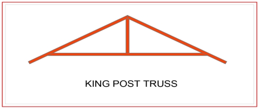
Queen Post Truss
A very reliable, simple and versatile type of roof truss where you can use at any given time. This kind of truss offers a span of around 10 meters, and has a simple design which makes it perfect for a wide range of establishments.
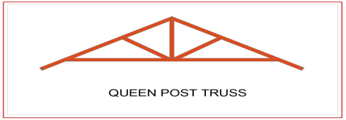
Howe Truss
A kind of truss having upper and lower members, a combination of steel and wood or both. One thing that makes this truss extraordinary is that it has a very wide span, as it can cover anything from 6-30 meters. This is very useful for a wide range of project types.
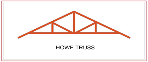
Pratt Truss
The prat truss is the most popular steel truss since it is very economical. It includes vertical and diagonal members that slope down towards the center (opposite of Howe Truss). Pratt truss can cover lengths ranging between 6-10 meters.
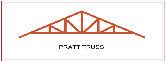
1. DEAD LOADS-
It includes the weight of sheeting purlins bracings, self weight and other loads suspended from trusses.
The unit weight of various material are given in IS875 part is. The following values may be noted-
GI sheets 85N/m2
AC sheets 130N/m2
In general the roof covering weight including lap, connectors etc may be taken as
1- 100-150 N/m2 for GI sheeting
2- 170-200N/m2 for A C sheeting
Weight of purlin should be added after designing purlin. Generally it works out 100-200N/m2 of plan area.
There are various formulae suggested to assume the self weight of the truss. These formulae economically used for a truss of span L
1- W=20+6.6L N/m2 for a LL of 2KN/m2
2- W=10(L/3 +5) s/4 N/m2 if LL is more than above value
Where s= spacing of truss
2. LIVE LOAD (IMPOSED LOAD)
IS875 part II makes the following provisions for live loads for the design of sheets and purlins.
Upto 10 degree slope -0.75kN/m2
For more than 10 degree slope -0.75-0.02(α-10)
Where α is the slope of sheeting
However a minimum of 0.4 Kn/m2 live load should be considered in any case.
For the design of truss the above live load may be reduced to 2/3 radians
The purlins and sheets should be checked to support a concentrated load of 0.9 kN at the worst position.
3. WIND LOAD-
IS875 part III gives the guidelines to determine wind forces on different components of buildings . It consists of the following steps
a- Determine basic wind speed
b- Obtain design wind speed
c- Calculate design wind pressure
d- Calculate wind pressure on roof
The steps are explained below-
a- Determine basic wind speed-(Vb)
For finding basic wind pressure in any place of india IS 875 par III divides the country into six zones as shown in fig. it is based on peak gust velocity averaged over a short time interval of about 3 seocnds studied over a period of 50 years . The value correspond to the speed at 10m height above ground level and in open terrain. For imp cities the basic wind pressure are given in the code. It may be observed that highest basic wind speed is 55m/s and lowest is 33 m/sec
b- Design wind speed (Vt)
The design wind speed of any site may be
Vt=k1 k2 k3 Vb
Where k1= risk coefficient
K2= terrain, height and structure
K3=topography factor
Risk coefficient (k1)-depending upon the importance of the building and basic wind speed IS875 has developed an equation to determine risk coefficient k1 for different types of buildings. These values shown in the table-
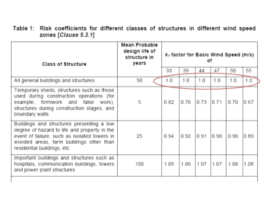
Terrain, height and structure size factor (k2)-
This coefficient depends upon terrain of the building site , height of the building and site of the building and class of building.
Buildings are classified into various classes-
Class A-buildings having maximum dimension less than 20m
Class B-Building having maximum dimension between 20 to 50m
Class C- building having maximum dimension greater than 50m
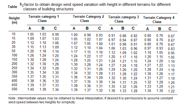
Topography factor (k3)-this factor is to account for the topographic features which influence design wind speed . Topographic features such as hills , valleys , cliffs etc
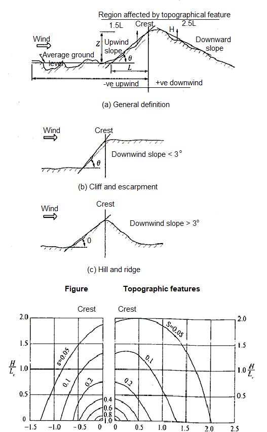
c- wind pressure-
The design wind pressure at any height above means ground level shall be calculated by following equation-
Pz=0.6 Vz2
Where
Pz=design wind pressure in N/m2at height z
Vz= design wind velocity in m/sec at height z
d- wind pressure on roof-
For calculating the wind load on individual structural elements it is essential to take into account of pressure difference between opposite faces of such elements. If internal as well as external pressure are found then wind load acting in a direction normal to the individual structural element is-
F=(Cpe - Cpi) A pd
Where Cpe= external pressure coefficient
Cpi= internal pressure coefficient
A= surface area
Pd=design wind pressure (N/m2)
Buildings with Cpi
Low permeability (less than 5% openings in wall area) ± 0.2
Medium permeability (5 – 20 % opening in wall) ± 0.5
Large openings (openings > 20% in wall) ±0.7
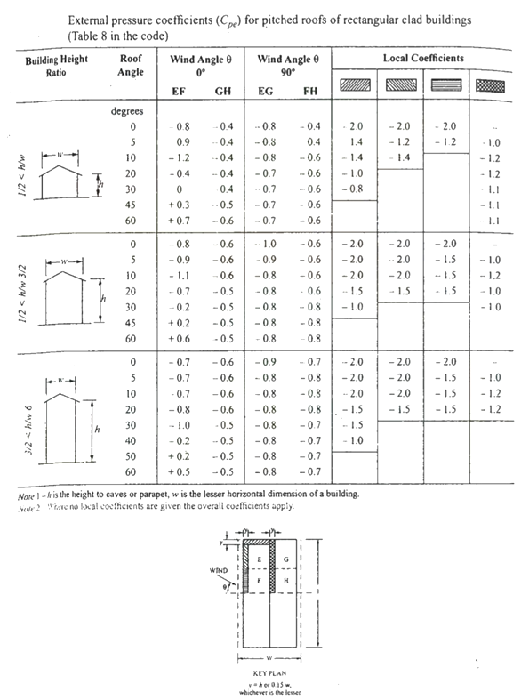

Key takeaways:
For the design of truss the above live load may be reduced to 2/3 radians
The purlins and sheets should be checked to support a concentrated load of 0.9 kN at the worst position.
References:
1. Design of Steel Structure, N Subramanian, Oxford University Press, New Delhi
2. Limit State Design in Structural Steel, M. R. Shiyekar, PHI, Delhi
3. Fundamentals of structural steel design, M L Gambhir, Tata McGraw Hill Education Private limited, New Delhi.
4. Structural Design in Steel, Sarwar Alam Raz, New Age International Publisher
5. Limit State Design of Steel Structure, V L Shah & Gore, Structures Publication, Pune