Unit - 4
Design of single rolled steel section column
To design a compression member, length, end conditions and load it has to support are required.
The designer is supposed to select a section which provides a large radius of gyration without providing more area and in which the design compressive strength (P) just exceeds the factored compressive load.
To find compressive strength, the area of cross section and radius of gyration must be known. So cut of these two unknown, one unknown should be assumed and compute other. Then section is checked
Step (1): The design compressive stress (F) is to be assumed.
There is no proper estimation of slenderness ratio for any length and support condition, therefore for a trial, range of F for slenderness ratio given below.
(a) For Angle strut: The slenderness ratio varies from 110 to 130. Hence assume F in between 80 to 110
(b) For rolled beam sections: The slenderness ratio varies from 70 to 100. Hence assume F in between 110 to 180 MPa.
Notes: For a columns with heavy factored load and large lengthy height, required large radius of gyration. Therefore built up sections are required to the selected for design
Step (2): Selection of section:
A required= P/fcd
Step (3): Classification of section
Step (4): Knowing and conditions and determine effective length (kl). Also find out slenderness ratio.
Step (5): Determine buckling class using table 10 of IS 800-2007
Step (6): Determine design compressive stress (f)
Step (7): Determine design compressive strength P
Using Pd= Ae.fcd>P Safe
Step (8): Revise the section if P,<P (factored load) till it will safe.
Example-a column 4m long has to support a factored load 6000kN. The column is effectively held at both ends and restrained in direction at one ends. Design the column using beam section using plates.
Let us assume fcd=200 N/mm2
Area required = 6000*1000/200=30000mm2
From steel table using ISHB450@907N/m
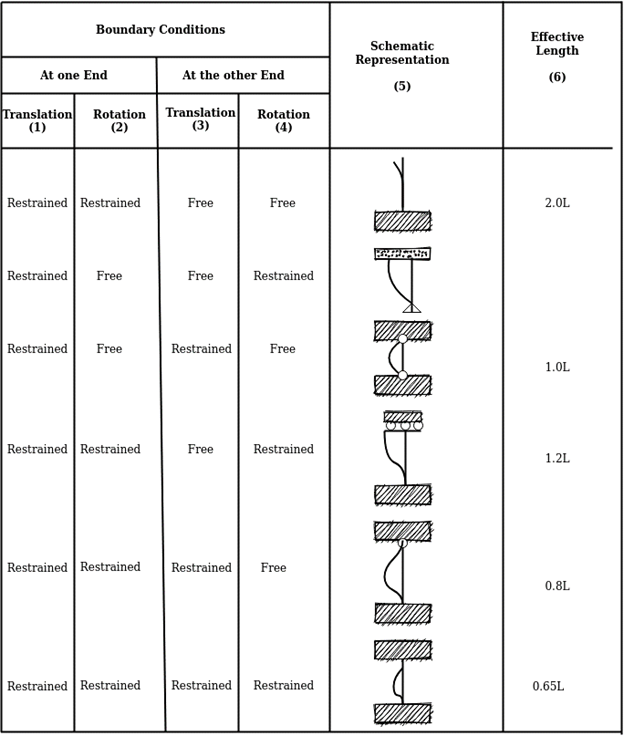
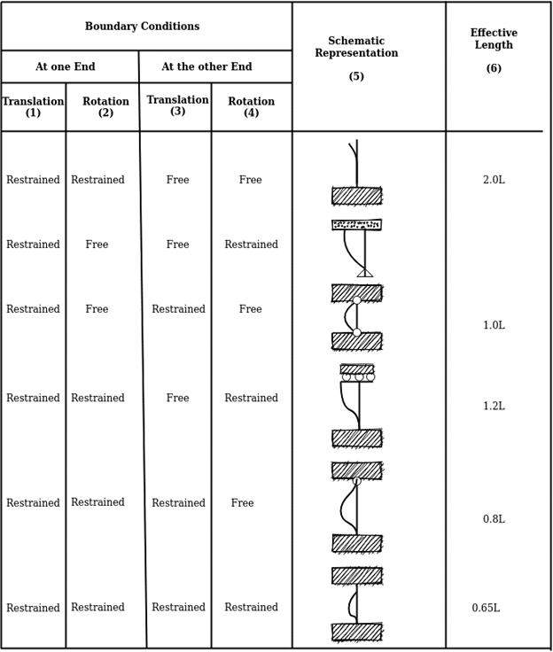
Effective length of prismatic compression members
[Refer Table in IS 800]
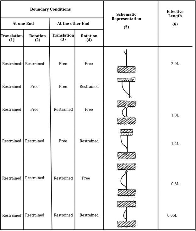
A=11789mm2, width of flange=250mm
Hence area to be provided by plates=30000-11789=18211mm2
Selecting 20mm plates breadth required
2b*20=18211
b=455.3
Provide 20mm*500mm plate
Total area provided = 11789+500*20*2
=31789mm2
For ISHB450@907N/m
Ixx=40349.9*10000 mm4
Iyy=3045*10000 mm4
For section selected Ixx=40349.9*10000+2*500*20(225+10)2
=1507.99*106
Iyy=3045*10000+2*20*5003/12
=447.1167*106
R=Rmin=118.6mm
Effective length Le=0.8L=0.8*4000=3200,mm
SR= 3200/118.6 =26.98
Table 6.4 for S R=20 fcd=211
SR=30 fcd=224
Fcd=224- 6.98(224-211)/10 =214.9 N/mm2
Hence Pd= 214.9*31789=6831456N=6831.45kN>factored load ok
Example 2 A single angle discontinuous strut ISA 150 mm x 150 mm x 12 mm (ISA 150 150, @0.272 kN/m) with single riveted connection is 3.5 m long. Calculate safe load carrying capacity of the section.
Solution:
Step 1: Properties of angle section
ISA 150 mm x 150 mm x 12 mm (ISA 150 150, @0.272 kN/m) is used as discontinuous strut. From the steel tables, the geometrical properties of the section are as follows:
Sectional area A = 3459 mm2
Radius of gyration rxx= ryy=149.3 mm
Radius of gyration ruu= 58.3 mm, rvv=29.3 mm
Step 2: Slenderness ratio,
Minimum radius of gyration rmin= 29.3 mm
Effective length of strut l= 3.5 m
Slenderness ratio of the strut
Step 3: Safe load
From IS:800-1984 for l/r=119.5 and the steel having yield stress, fy=260 N/mm2, allowable working stress in compression σac =64.45 N/mm2 (MPa)
For single angle discontinuous strut with single riveted connection, allowable working stress
0.80 σac = (0.80 x 64.45) = 51.56 N/mm2.
The safe load carrying capacity

Example 3: In case in Example 2, a discontinuous strut 150 x 150 x 15 angle section is used, calculate the safe load carrying capacity of the section.
Solution:
Step 1: Properties of angle section
Angle section 150 mm x 150 mm x 15 mm is used as discontinuous strut. From the steel tables, the geometrical properties of the section are as follows:
Sectional area A = 4300 mm2
Radius of gyration rxx= ryy=45.7 mm
Radius of gyration ruu= 57.6 mm, rvv=29.3 mm
Step 2: Slenderness ratio,
Minimum radius of gyration rmin= 29.3 mm
Effective length of strut l= 3.5 m
Slenderness ratio of the strut

Step 3: Safe load
From IS: 800-1984 for l/r=119.5 and the steel having yield stress, fy=260 N/mm2, allowable working stress in compression σac =64.45 N/mm2 (MPa)
For single angle discontinuous strut with single riveted connection, allowable working stress
0.80 σac = (0.80 x 64.45) = 51.56 N/mm2.
The safe load carrying capacity

Example 4: In Example 2, if single angle discontinuous strut is connected with more than two rivets in line along the angle at each end, calculate the safe load carrying capacity of the section.
Solution:
Step 1: Properties of angle section
Discontinuous strut ISA 150 mm x 150 mm x 12 mm (ISA 150 150, @0.272 kN/m) is used with double riveted connections. From the steel tables, the geometrical properties of the section are as follows:
Sectional area A = 3459 mm2
Radius of gyration rxx= ryy=149.3 mm
Radius of gyration ruu= 58.3 mm, rvv=29.3 mm
Length of strut between center to center of intersection L=3.50 m
Step 2: Slenderness ratio,
Minimum radius of gyration rmin= 29.3 mm
Effective length of discontinuous strut double riveted 0.85 x L= 0.85 x 3.5 = 2.975 m
Slenderness ratio of the strut

Step 3: Safe load
From IS:800-1984 for l/r=101.5 and the steel having yield stress, fy=260 N/mm2, allowable working stress in compression σac =71.65 N/mm2 (MPa)
Allowable working stress for discontinuous strut double riveted is not reduced.
The safe load carrying capacity 
Example 5: A double angle discontinuous strut ISA 125 mm x 95 mm x 10 mm (ISA 125 95, @0.165 kN/m) long legs back-to-back is connected to both the sides of a gusset plate 10 mm thick with 2 rivets. The length of strut between center to center of intersections is 4 m. Determine the safe load carrying capacity of the section.
Solution:
Step 1: Properties of angle section
The double angle discontinuous strut 2 ISA 125 mm x 95 mm x 10 mm (ISA 125 95, @0.165 kN/m) is shown in Fig. 11.4. Assume the tacking rivets are used along the length. From the steel tables, the geometrical properties of (two angle back-to-back) the sections are as follows:
Sectional area A = 4204 mm2
Radius of gyration rxx= 39.4 mm
Angles are 10 mm apart
Radius of gyration ryy= 40.1 mm
Length of strut between center to center of intersection L=4 m
Step 2: Slenderness ratio,
Minimum radius of gyration rmin= 39.4 mm
Effective length of discontinuous strut 0.85 x L= 0.85 x 4.0 = 3.40 m
Slenderness ratio of the strut

Step 3: Safe load
From IS:800-1984 for l/r=86.3 and the steel having yield stress, fy=260 N/mm2, allowable working stress in compression σac =95.96 N/mm2 (MPa)
The safe load carrying capacity

Step-1 Find the effective length from the actual length & end conditions
Step-2 assume suitable value of slenderness ratio between 30-60 for built up columns.
Step3- find allowable compressive stress for the given value of SR.
Step4- find area A=P/fcd
Step5 choose a built up section so that total area becomes more than that required area calculated in step4. Also arrange the members in such that the values of Ixx=Iyy
Step6- with the above arrangement find Rmin and calculate SR and find fcd.
Step7- calculate the developed compressive stress in the built up section and check for fcd,cal.
Fcd,cal<fcd ok
Example –design a built up column of length 9m which is effectively held in position at both ends but not restrained against rotation at one end . It is constructed by using 4 –ISA 100*100*10. They carry factored load of 750kN.
Solution- ISA 100*100*10
A=1903mm2
Cxx=Cyy=28.4mm
Rxx=Ryy=30.5mm
Ruu=38.5mm
Rvv=19.4mm
Ixx=Iyy=177*10000 mm4
Fcd=P/A= 750*1000/4*1903 =98.52 N/mm2
SR (required)= 80+ (101-98.52)/101-90 *(90-80)
=82.25
SR (req)= Le/Rmin
82.25= 0.8*9000/Rmin
Since lacing is provided eff. Length of column is increased by 5%
Rmin (req)= 91.91mm
From Rmin we can find out min moment of inertia-
Imin= 64.3*10^6(required)
Imin (provided)= 4(Ixx+ A.h2)
=4( 177* 10^4 + 1903* 71.6^2)
=46.1*10^6 mm4 < Imin (req) ok unsafe
Spacing of angles
64.3*10^6= 4{ 177*10^4 +1903 *(71.6+ s/2)2 }
S=30mm
Built-up sections are preferred instead of rolled steel sections for a column in industrial buildings because.
(1) Span and height of industrial buildings are large, so the load on the columns are enough large such that available rolled steel sections are unable to sustain loads.
(2) Also, built up sections are designed such that the radius of gyration about tow principal axes is same.
(3) Lacing and battening in built up column restrain lateral buckling of column.
(4) Finally, design strength of built up sections more than available rolled steel sections.
Lacing and battening are used in built up section of column is large for toll purpose. (1) To restrain lateral buckling of column section as the height of built up column is large.
(2) The sections of built up column to act a single section.
Design of Laced Column
Procedure
(A) Design of Column
1) The design compressive stress is assumed. It is difficult for an excellent assumption of slenderness ratio or design compressive stress. Is in the range of 125 to 185 MPa assumed for f,= 250 MPa of steel.
2) Selection of cross section:

Where,
A = Cross-sectional area in mm²
P= Factored axial compressive force.
A suitable section comprising of two channels of four channels or four angles or two I sections with or without extra plates as required is selected from steel table.
(3) Effective length (kL) depends upon end /support conditions is determined and the slenderness ratio is determined.
The effective slenderness of laced column should be taken as in order to account for  ratio 1.05 times
  deformation effect.

(4) For the estimated value of the slenderness ratio the design compressive stress (f) is computed from Table 9(a), (b), (c) and (d).
5) The design compressive strength is computed. It should be more than the factored load over the section.

(6) The sections are so placed that the radius of gyration of section about the axis perpendicular to the plane of lacing is not less than the radius of gyration about the axis in the plane of lacing. This is achieved by making ryy>rzz
(B) Design of Lacing Bar
(1) Angle of inclination of lacing bar with the longitudinal axis of the component member should be kept between 40"-70". As an initial trial value 0 may be assumed to be 45° and the spacing of lacing bars a, r, is calculated.
(2) The maximum spacing of lacing bars a, should be such that minimum slenderness ratio of the component member a/r, is not greater than 50 or 0.7 times the slenderness ratio of the member as a whole,
Where, a, = is the length of component member.
Ryy=radius of gyration @ y-y axis.
(3) The lacing for compression members should be proportioned to resist a total transverse shear v₁= 2.5% of axial load. This shear v, is divided equally in all parallel planes N in which there is shear resisting elements, such as lacing or continuous plates. Hence v/N is the transverse force to which the lacing is subjected N=2 for two channels laced on both faces.
The compressive force in the lacing bar
 For single lacing system
 For double lacing system
The section of the lacing flat initially assumed and then check for safety.
(1) Diameter of bolt or rivet assumed (d)
(ii) Width = b > 3d
(iii) Thickness = t
For single lacing

For double lacing

(6) rmin of lacing flat 
(7) 
Where, KL = Distance between inner end bolts (for single lacing)
= 0.7 x L for double lacing
= 0.7 x inner length of plate weld.
(8) Design compressive stress (f) is determined and also design compressive strength of lacing plate is calculated which should be more than 'c'.
(9) Determine tensile strength of lacing plate using yielding of gross cross-section and rupture at net cross section.
(10) Design the connection (bolted or welded)
(11) Detailing.
Battening and its connections
Compression members composed of two main components battened should preferably have the individual members of the same cross-section and symmetrically disposed about their major axis.
Where practicable, the compression members should have a radius of gyration about the axis perpendicular to the plane of the batten not less than the radius of gyration about the axis parallel to the plane of the batten.
The battens should be placed opposite to each end of the member and at points where the member is stayed in its length and as far as practicable, be spaced and proportioned uniformly throughout.
The number of battens shall be such that the member is divided into not less than three bays within its actual length from center to center of end connections.
The effective slenderness ratio (KL/r) c of battened columns, shall be taken as 1.1-time (KL/r) o, the maximum actual slenderness ratio of the column, to account for shear deformation effects.
Design of Battens:
Battens shall be designed to carry the bending moments and shear forces arising from transverse shear force Vt equal to 2.5 per cent of the total axial force in the whole compression member, at any point in the length of the member divided equally between parallel planes of the battens.
Battened member divided equally between parallel planes of the battens.
Battened member carrying calculated bending moment due to eccentricity of axial loading, calculated end moments or lateral loads parallel to the plane of battens, shall be designed to carry actual shear in addition to the above shear.
The main members shall also be checked for the same shear force and bending moments as for the battens.
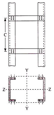
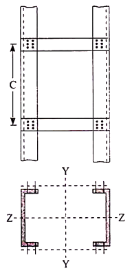
Battens shall be of plates, angles, channels or I-sections and at their ends shall be riveted, bolted or welded to the main components so as to resist simultaneously a shear Vb = (V1C)/N5 along the column axis and a moment M = (V1C)/2N at each connection.
Where,
V1 = Transverse shear force as defined above
C = Distance between center to center of battens, longitudinally
N = Number of parallel planes of battens, and
S = Minimum transverse distance between the centroid of the rivet/bolt group/welding connecting the batten to the main member.
A lacing system should generally conform to the following requirements:
- The compression member comprising two main components laced and tied should, where practicable, have a radius of gyration about the axis perpendicular to the plane of lacing not less than the radius of gyration at right angles to that axis.
- The lacing system should not be varied throughout the length of the strut as far as practicable.
- Cross (except tie plates) should not be provided along the length of the column with lacing system, unless all forces resulting from deformation of column members are calculated and provided for in the lacing and its fastening.
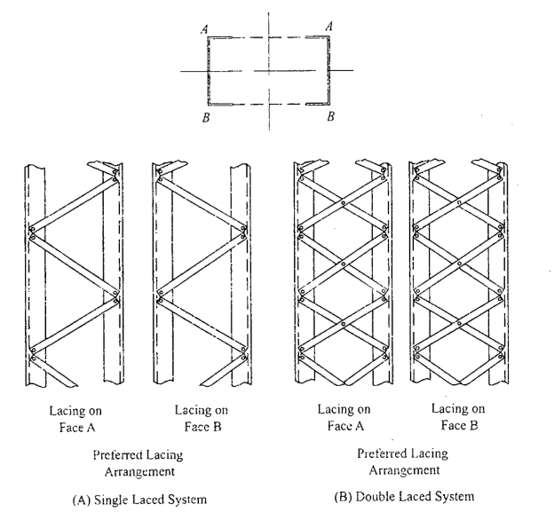
- The single-laced systems on opposite sides of the main components should preferably be in the same direction so that one system is the shadow of the other.
- Laced compression members should be provided with tie plates at the ends of the lacing system and at points where the lacing system are interrupted. The tie plates should be designed by the same method as followed for battens.
As per IS800 the following rules for the design of laced columns are as follows-
- The angle of inclination of the lacing with the longitudinal axis of the column should be between 40o to 70o.
- The slenderness ratio λ = le/γ of the lacing bars should not exceed 145.
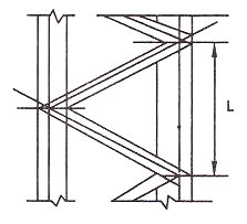
- For riveted or welded lacing system, (L/γe, min) ≯ 50 or 0.7 times maximum slenderness ratio of the compression member as a whole, whichever is less.
Here, L = distance between the centers of connections of the lattice bars, and
γe, min= the minimum radius of gyration of the components of the compression member.
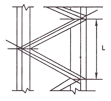
Iv. In bolted / riveted construction the minimum width of lacing bar shall be three times the nominal diameter of rivet/ bolt.
v. The lacing shall be designed to resist transverse shear equal to 2.5%of axial force in the columns .
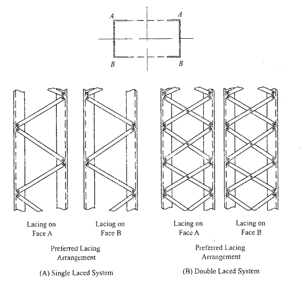
Vi. Laced compression members shall be provided with end tie plates.
Vii. The effective slenderness ratio of laced columns shall be taken as 1.05 times the actual maximum slenderness ratio .
Viii. Minimum thickness of lacing bars:
t ≮ l/40 , for single lacing;
t ≮ l/60, for double lacing
Where l = length between inner end rivets.
Connections-
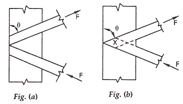
- The riveted connections may be made in two ways, as shown in the figure (a) and (b).
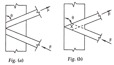
Minimum width of lacing bars in riveted connection should be according to the Table given below:
Nominal rivet diameter (mm) | 22 | 20 | 18 | 16 |
Width of lacing bars (mm) | 65 | 60 | 55 | 50 |
Lap Joint – Overlap should not be less than ¼ times thickness of bar or member, whichever is less.
Butt Joint – Full penetration butt weld or fillet weld on each side, lacing bar should be placed opposite to flange or stiffening component of main member.
Ex-Design a laced columns with two channels back to back of length 10m to carry an axial factored load of 1400KN. The column may be assumed to have restrained in position but not held in position at both ends?
Solution- assume fcd=135N/mm2
Area required =1400*1000/135=10370mm2
Try 2 ISMC350@413N/m
Area provided=2*5366=10732mm2
.rzz=136.6mm
Slenderness ratio=Le/r=1*10000/136.6=73.206
Since it is a laced column SR=1.05*73.206=76.87
Table 6.1
.fcd=152-6.87/10(152-136)=141N/mm2
Load carrying capacity-=10732*141=1513297N=1513.297kN>1400kN ok
Spacing between the channels=d
Ixx=2*10008*10000=200160000 mm4
Iyy=2[430.6*104+5366(d/2+24.4)2]
Equating Iyy to Ixx we get
200160000=2[430.6*104+5366(d/2+24.4)2]
(d/2+24.4)2=17848.3
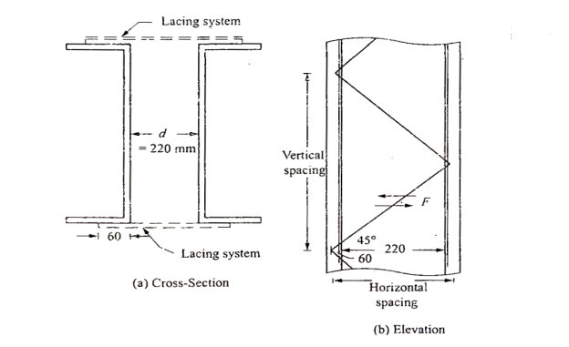
d=218.4mm=220mm as shown in fig
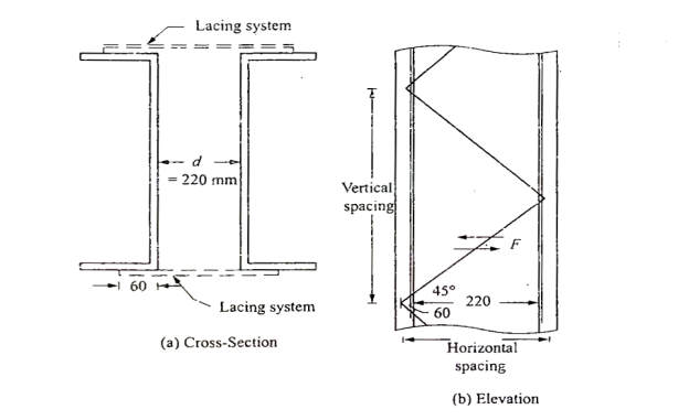
Lacing-let the lacing be provided at 45 degree to horizontal
Horizontal spacing of lacing=220+60+60=340mm(note60= gauge distance)
Hence vertical spacing =340tan 45*2=680mm
.least r of the channel=ryy=28.3mm
Le/r of the channel between lacing =680/28.3=24.03<50 ok
Transverse shear to be resisted by lacing stystem=2.5*1400*1000/100=35000N
Shear to be reisted by each lacing system=35000/2=17500N
Length of lacing=220+60+60)*1/cos45=480.83mm
Minimum thickness of lacing=1/40*480.83=12.02mm
Use 14mm flats
Minimum width of lacing if 20mm bolts are used=3*20=60mm
Use 60ISF 14
Sectional area=60*14=840mm2
.rmin=√60*143/12/60*14=4.041mm
SR=480.83/4.041=118.97<145 ok
Strength of 20mm shop bolt-
1- In single shear=0.78*3.14/4*202*(400/√3 *1.25)=45272N
Edge distance =60/2=30mm
Kb=30/3*22=0.4545
2- Strength in bearing =2.5Kb*d*t*fu/1.25=2.5*0.4545*20*10*400/1.25
=101808N
Therefore bolt value=45272N
No of bolts required= 17500/45272=0.387=1 bolt
Check for strength of lacing-
Le/r=118.97
A flat belong to class c
.fcd=94.6-8.97/10(94.6-83.7)=84.82N/mm2
Load carrying capacity in compression=84.82*60*14=71251N
Force in lacing =17500/sin45=24749N<71251N ok safe
Hence provide 60ISF 14 flats at 45 degree and connect them to centre of gravity of channels with one bolt of 20mm nominal diameter.
DESIGN OF BATTEN & CONNCETION OF BATTENING WITH MAIN COMPONENTS BY BOLT/WELD-
Compression members composed of two main components battened should preferably have these components of the same cross-section and symmetrically disposed about their X – X axis.
The battens should be placed opposite to each-other at each end of the member and at points where the member is stayed in its length, and should as far as practicable, be spaced and proportioned uniformly throughout.
The effective length of columns should be increased by 10 percent.
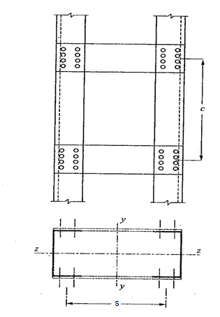
Design Details of Battens
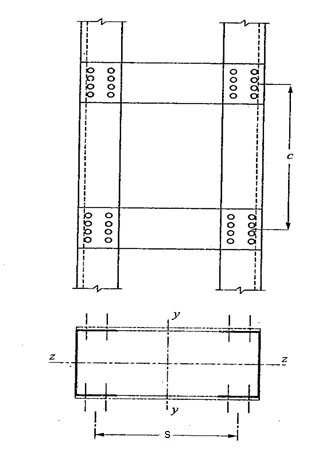
- Spacing of batten C, from centre-to-centre of end fastening should be such that the slenderness ratio of the lesser main component, (C/γe, min) ≯ 50 or 0.7 times the slenderness ratio of the compression member as a whole about X – X axis (parallel to battens) whichever is less.
- The min. No. Of battens =4 so that the columns into min of 3 bays.
- Battens shall be plates , angles , channels, and at their ends shall be riveted bolted and welded.
- Effective depth of battens, d shall be taken as distance between end rivets or end welds.
d > ¾ a for intermediate batten
d > a, for end batten
d > 2b , for any batten
Where d = effective depth of batten
a = centroidal distance of members
b = width of members in the plane of battens.
- Thickness of battens, t > (lb/50)
Where, lb = distance between the innermost connecting line of rivets or welds.
5. Battens should be designed to carry bending moment and shear arising from a transverse shear,
V = 2.5 P/100
Where P = total axial load in the compression member.
Transverse shear V is divided equally between the parallel planes of battens. Battens and their connections to main components resist simultaneously a longitudinal shear.
V1 = V C/N S
And , moment M = (F C)/2N
Due to transverse shear V.
Where, C = spacing of battens
N= number of parallel planes of battens
S= minimum transverse distance between centroid of rivet group or welding.
The end connections should also be designed to resist the longitudinal shear force V1 and the moment M.
6. The effective slenderness ratio of battened columns shall be taken as 1.1 times the maximum actual SR of the column
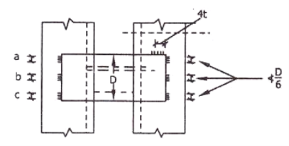
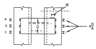
For welded connection
- Lap < 4t
- Total length of weld at edge of batten < D/2
a + b+ c < D/2
Let t = thickness of batten
Length of continuous weld at each edge of batten < 1/3 of total length required.
Return weld along transverse axis of the column < 4t
Where, t and D are the thickness and overall depth of battens, respectively.
Example- design a battened column with two channels back to back of length 10m to carry an axial factored load of 1400kN. The columns assumed to have restrained in position but not in direction at both ends?
Solution=
Assume fcd=135N/mm2
Area required A= 1400*1000/135 =10370mm2
Try 2 ISMC 350@413 N/M with clear spacing 220mm
A= 2*5366=10732mm2
Rzz=136.6mm
SR= 1.1*10000/136.6 =80.52
Distance between centres of channel S= 220+60+60=340mm
Let C be the spacing of batten longitudinally
Radius of gyration of one channel = 28.3mm
Hence C/28.3 <50 i.e C<1415
Let us select C=1200mm
Vt= 25/100 *1400*1000 = 35000N
Vb= Vt C/N S = 35000* 1200/2*340 = 61765N
M= Vt C/2N=35000*1200/2*2=10500000N-mm
Size of battens-
Provide eff depth <268.8mm and also < 2*100mm
Provide 270 mm depth for end battens , overall depth = 270+ 2*edge distance (35)
=340mm
For intermediate batten it is < ¾*270mm and < 200mm
Provide depth =210mm
Overall depth=210+2*35=280mm
Thickness of battens<1/50*340
<6.8
Use 8mm thick plates.
Check for stress in batten plates-
Shear stress=61765/280*8=27.57 N/mm2 < fy/1.73*1.1 ok
Bending stress = 6M/td2 =6*10500000/8*2802
100.45<227.27 N/mm2 ok
Column bases, slab base, gusseted base, and moment resistant bases
The columns are supported at the column bases. The column bases transmit the column load to the concrete or masonry basis blocks.
The column load is unfold over massive location on concrete or masonry blocks. The depth of bearing stress on concrete or masonry is stored inside the most permissible bearing stress.
The protection of the shape relies upon up on balance of basis. The column bases need to be designed with utmost care and skill. In the column bases, depth of stress on concrete block is thought to be uniform.
The column bases will be of ok strength, stiffness and location to unfold the burden upon the concrete, masonry, different basis or different helps without exceeding the allowable strain on such basis below any mixture of the burden and bending moments.
The column bases are of types;
- Slab base
- Gusseted bases
- Slab base
The column give up is confronted for bearing over the complete area. The gussets (gusset plates and gusset angles) aren't supplied with the column with slab bases. The enough fastenings are used to hold the elements securely in plate and to withstand all moments and forces, apart from the direct compression. The forces and moments springing up all through transit, unloading and erection also are considered. When the slab by myself distributes the weight uniformly the minimal thickness of a square slab is derived as below;
Procedure
Step 1) Assume a suitable grade of concrete. Depending upon the grade of concrete used bearing strength of concrete is determine by 0.45fck
Step 2) The area of a slab base may be computed by
A= P/ bearing strength of concrete
Where,
A= area of base plate
P= Factored load
Step 3) A square base plate is generally provided. The side of the base plate may be worked out
L= B= 
Some designer feel that the projections of the base plate beyond column edges a and b are kept equal and these sides can be work out.
Using
( D+2b) x (bf+2a)= A
Where,
L= length of base plate in mm
B= width of base plate in mm
D= depth of column section in mm
Step 4) The intensity of pressure w from the concrete pedestal is determine by
W= P/A1
Where, w= intensity of pressure from concrete under the slab base
A1= Area of base plate provided in mm2
Step 5) The minimum thickness ts of the base plate is calculated by using

Step 6) Holding down bolts 2 or 4 in number and of 20 mm diameter are usually provided. When the base subjected to only axial compressive load two bolt will be enough.
Step 7) welded joint between the column and base plate is designed.
Step 8) Detailing
2. Gusseted base
Procedure
Step 1) Bearing strength of concrete is determined = 0.45 f
Step 2) Area of the base plate may be computed by,
A = P/0.45 fck
Step 3) The size of gusset base assumed
(i) Thickness: For bolted gusset base t <16 mm.
(ii) The gusset angle is chosen so as to accommodate two rows of bolts in the vertical leg and one row of bolt in the horizontal leg. Therefore an unequal angle section is provided.
(iii) The thickness of gusset angle should be same as thickness of gusset plate.
(iv) Width of base plate.
L = depth of section + 2 (thickness of gusset plate +
leg length of angle + over hang) (for bolted connections)
L = depth of section + 2x (thickness of gusset plate + overhang)
(for welded connections)
(v) Width of base plate
B = A/L
Step 4) The intensity of bearing pressure
W = P/A1
Where
A₁ = Area of base plate provided
Step 5) The thickness of the base plate is computed by equating the moment at the critical section to the moment of resistance of the gusset at that section.
B.M. At critical section
M = wc12/2(considering unit width)
Where
c.- Minimum over hang
Design bending moment at critical section M, 12

Now equating, M = Md


Where,
t= Total thickness including thickness of base plate and gusset angle (for bolted gusset base)
= Thickness of base plates (for welded gusset base)
W= Intensity of pressure from concrete under the slab faze.
C₁=Cantilever portion of base plate
Step 6) Holding down bolts 2 or 4 in numbers and of 20 diameter are usually provided.
Step 7) Design connection
Step 8) Detailing
Q.1 Design a slab base for the column consisting of ISMB 400@ 61.6 kg/m carrying an axial factored load of 450kN. Use M20 grade of concrete.
Solution:
- Area of base plate


2. Size of base plate
Provide 430 x 170 mm size of base plate
Area provide = 73100> A required
3. Intensity of pressure w from concrete pedestal
w = P/A provides


4. Thickness of base plate (ts)

Provides base plate of size 430 x 170 x 16 mm
Q.2 Design a slab base for a column ISHB 350 @ 67.4 kg/m carrying a factored load of 1000 kN. Also design the welded connection between slab base and column. Use concrete grade M20 and Steel of Fe410
Solution:
- Bearing Strength of concrete

2. Area of base plate

3. Size of base plate
Provide 410 x 310 size of base plate

4. Intensity of pressure w from concrete pedestal

Projection


5. Thickness of base plate

Thickness of flange of ISHB 350 @ 67.4 kg/m is 11.6 mm
Provide 410 x 310 x1 2 mm plate to carry load
6. Design of anchor bolts
Use a bolts of 20 mm diameter of 300 mm long to anchor the plates
7. Design fillet weld column is fixed over a base plate
Using fillet weld of column is fixed over a base plate
Total length available for welded

Strength of weld

Let a be the size of weld
Then effective area of weld = 0.7 x a x Le
Equating to the strength by assuming the size of weld 6 mm


Available effective length


Hence Provide 6 mm size of fillet weld
Q.3 Design the section of steel column and suitable base for an axial compressive factor load of 3000 kN. The effective length of column is 6 m The grade of concrete used for pedestal is M30.
Solution:
- Factored load P
P= 3000 KN
KL= 6000 mm
Fy = 250 MPa
Assuming Fcd = 200 MPa
2. Selection of section
Area of required = 
Provided built up section 2 ISLC 400 @ 45.7 kg/m with cover plate of 420 X6 mm shown in
Properties
A= 5825 mm^2
D = 400 mm
Bf = 100 mm
Tf = 14 mm
Tw = 8 mm
C = 23.6 mm
Izz = 11989.5 x 10 ^4 mm^4
Iyy= 460.4 x 10^4 mm^4
Area Provided
5825x2+2x420x6 = 16690 mm^2 > A required
3. Design strength (pd)
Slenderness ratio = 
Buckling class for built up section is C
Using table 9(c)
Design compressive stress
Fcd = 202.47 MPa
Design strength (pd) = Ae x Fcd = 16690 X 202.47 = 3379.2 kN
4. Design of slab base
As M30 grade concrete used for pedestal
Required area of base plate

Providing nominal cleat angle of 65 x 65 x 8 mm
Minimum width of base plate
2x65 + 420 = 550 mm
Length of base plate L = 460 mm
Area of base plate provided = 550 x 460
A1= 253000 mm^2 > Area Required
Bearing pressure of concrete on base plate

Projections


Thickness of base plate

Hence Safe
Provide base of size 550 x 460 x 24 mm Thick
Q.4 Design a slab base for the column consisting of ISWB 300 @ 48. 1kg/m carrying an axial factored load of 1100 KN. Design welded connection between column and base plate. Concrete of grade M20 is available.
Solution:
Design of slab base for column ISWB 300 @ 48.1kg/m
- Factored load P = 1100 KN
- Bearing strength of concrete
= 0.45 fck = 0.45 x 20 = 9 N/mm^2
3. Size of base plate

Provide size of base plate 410 x 310 mm
4. Thickness of base plate

Projections


Thickness of base plate

Provided 410 x310 x 16 mm plate for slab base
5. Design of welded connection
Length of weld available

Assuming size of weld 6 mm


Available effective length
= 1365.2 – 2 x 6 x12 = 1221.2 mm < Lw required
Unsafe
Hence provide 9 mm size of fillet weld for a 1200 mm length
Q. 5 Design a base plate for column of ISHB 250 @ 51.0 kg/m carrying a factored load of 650 KN. Assume that the column is supported on a concrete of grade M 25
Solution:
- Bearing strength of concrete
0.45 fck = = 0.45 x 25 = 11.25 MPa
Area of base plate

2. Size of base plate


3. Intensity of pressure w from concrete pedestal

Projections


4. Thickness of base plate

Thickness of flange of ISHB 250 @ 51 kg/m is 9.7 mm
Provide ts = 10 mm thick base plate
Provides base plate of size 310 x 310 x 10 mm
Plate to carry load safety
Q.6 Explain types of column bases and design the size of slab for a column ISHB 350 @ 67.4 kg/m supporting a factored axial compression of 1200KN consider grade of concrete as M20
Solution:
1.Geometrical properties of ISHB 350 @ 67.4 kg.m
h = 350 mm
Bf = 250 mm
Tf = 11.6 mm
8.3 mm
2.Size of base plate
Area required =

Select 420 x 380 mm size of base plate
Area provided= 420 x 380
= 15.96 x 10^4 mm^2 > A required
3.Bearing pressure an base plate

4. Thickness of base plate
Assume


Provide base plate of size 420 x 380 x 12 mm for slab base
References:
1. Design of Steel Structure, N Subramanian, Oxford University Press, New Delhi
2. Limit State Design in Structural Steel, M. R. Shiyekar, PHI, Delhi
3. Fundamentals of structural steel design, M L Gambhir, Tata McGraw Hill Education Private limited, New Delhi.
4. Structural Design in Steel, Sarwar Alam Raz, New Age International Publisher
5. Limit State Design of Steel Structure, V L Shah & Gore, Structures Publication, Pune
Unit - 4
Design of single rolled steel section column
To design a compression member, length, end conditions and load it has to support are required.
The designer is supposed to select a section which provides a large radius of gyration without providing more area and in which the design compressive strength (P) just exceeds the factored compressive load.
To find compressive strength, the area of cross section and radius of gyration must be known. So cut of these two unknown, one unknown should be assumed and compute other. Then section is checked
Step (1): The design compressive stress (F) is to be assumed.
There is no proper estimation of slenderness ratio for any length and support condition, therefore for a trial, range of F for slenderness ratio given below.
(a) For Angle strut: The slenderness ratio varies from 110 to 130. Hence assume F in between 80 to 110
(b) For rolled beam sections: The slenderness ratio varies from 70 to 100. Hence assume F in between 110 to 180 MPa.
Notes: For a columns with heavy factored load and large lengthy height, required large radius of gyration. Therefore built up sections are required to the selected for design
Step (2): Selection of section:
A required= P/fcd
Step (3): Classification of section
Step (4): Knowing and conditions and determine effective length (kl). Also find out slenderness ratio.
Step (5): Determine buckling class using table 10 of IS 800-2007
Step (6): Determine design compressive stress (f)
Step (7): Determine design compressive strength P
Using Pd= Ae.fcd>P Safe
Step (8): Revise the section if P,<P (factored load) till it will safe.
Example-a column 4m long has to support a factored load 6000kN. The column is effectively held at both ends and restrained in direction at one ends. Design the column using beam section using plates.
Let us assume fcd=200 N/mm2
Area required = 6000*1000/200=30000mm2
From steel table using ISHB450@907N/m
Effective length of prismatic compression members
[Refer Table in IS 800]
A=11789mm2, width of flange=250mm
Hence area to be provided by plates=30000-11789=18211mm2
Selecting 20mm plates breadth required
2b*20=18211
b=455.3
Provide 20mm*500mm plate
Total area provided = 11789+500*20*2
=31789mm2
For ISHB450@907N/m
Ixx=40349.9*10000 mm4
Iyy=3045*10000 mm4
For section selected Ixx=40349.9*10000+2*500*20(225+10)2
=1507.99*106
Iyy=3045*10000+2*20*5003/12
=447.1167*106
R=Rmin=118.6mm
Effective length Le=0.8L=0.8*4000=3200,mm
SR= 3200/118.6 =26.98
Table 6.4 for S R=20 fcd=211
SR=30 fcd=224
Fcd=224- 6.98(224-211)/10 =214.9 N/mm2
Hence Pd= 214.9*31789=6831456N=6831.45kN>factored load ok
Example 2 A single angle discontinuous strut ISA 150 mm x 150 mm x 12 mm (ISA 150 150, @0.272 kN/m) with single riveted connection is 3.5 m long. Calculate safe load carrying capacity of the section.
Solution:
Step 1: Properties of angle section
ISA 150 mm x 150 mm x 12 mm (ISA 150 150, @0.272 kN/m) is used as discontinuous strut. From the steel tables, the geometrical properties of the section are as follows:
Sectional area A = 3459 mm2
Radius of gyration rxx= ryy=149.3 mm
Radius of gyration ruu= 58.3 mm, rvv=29.3 mm
Step 2: Slenderness ratio,
Minimum radius of gyration rmin= 29.3 mm
Effective length of strut l= 3.5 m
Slenderness ratio of the strut
Step 3: Safe load
From IS:800-1984 for l/r=119.5 and the steel having yield stress, fy=260 N/mm2, allowable working stress in compression σac =64.45 N/mm2 (MPa)
For single angle discontinuous strut with single riveted connection, allowable working stress
0.80 σac = (0.80 x 64.45) = 51.56 N/mm2.
The safe load carrying capacity

Example 3: In case in Example 2, a discontinuous strut 150 x 150 x 15 angle section is used, calculate the safe load carrying capacity of the section.
Solution:
Step 1: Properties of angle section
Angle section 150 mm x 150 mm x 15 mm is used as discontinuous strut. From the steel tables, the geometrical properties of the section are as follows:
Sectional area A = 4300 mm2
Radius of gyration rxx= ryy=45.7 mm
Radius of gyration ruu= 57.6 mm, rvv=29.3 mm
Step 2: Slenderness ratio,
Minimum radius of gyration rmin= 29.3 mm
Effective length of strut l= 3.5 m
Slenderness ratio of the strut

Step 3: Safe load
From IS: 800-1984 for l/r=119.5 and the steel having yield stress, fy=260 N/mm2, allowable working stress in compression σac =64.45 N/mm2 (MPa)
For single angle discontinuous strut with single riveted connection, allowable working stress
0.80 σac = (0.80 x 64.45) = 51.56 N/mm2.
The safe load carrying capacity

Example 4: In Example 2, if single angle discontinuous strut is connected with more than two rivets in line along the angle at each end, calculate the safe load carrying capacity of the section.
Solution:
Step 1: Properties of angle section
Discontinuous strut ISA 150 mm x 150 mm x 12 mm (ISA 150 150, @0.272 kN/m) is used with double riveted connections. From the steel tables, the geometrical properties of the section are as follows:
Sectional area A = 3459 mm2
Radius of gyration rxx= ryy=149.3 mm
Radius of gyration ruu= 58.3 mm, rvv=29.3 mm
Length of strut between center to center of intersection L=3.50 m
Step 2: Slenderness ratio,
Minimum radius of gyration rmin= 29.3 mm
Effective length of discontinuous strut double riveted 0.85 x L= 0.85 x 3.5 = 2.975 m
Slenderness ratio of the strut

Step 3: Safe load
From IS:800-1984 for l/r=101.5 and the steel having yield stress, fy=260 N/mm2, allowable working stress in compression σac =71.65 N/mm2 (MPa)
Allowable working stress for discontinuous strut double riveted is not reduced.
The safe load carrying capacity 
Example 5: A double angle discontinuous strut ISA 125 mm x 95 mm x 10 mm (ISA 125 95, @0.165 kN/m) long legs back-to-back is connected to both the sides of a gusset plate 10 mm thick with 2 rivets. The length of strut between center to center of intersections is 4 m. Determine the safe load carrying capacity of the section.
Solution:
Step 1: Properties of angle section
The double angle discontinuous strut 2 ISA 125 mm x 95 mm x 10 mm (ISA 125 95, @0.165 kN/m) is shown in Fig. 11.4. Assume the tacking rivets are used along the length. From the steel tables, the geometrical properties of (two angle back-to-back) the sections are as follows:
Sectional area A = 4204 mm2
Radius of gyration rxx= 39.4 mm
Angles are 10 mm apart
Radius of gyration ryy= 40.1 mm
Length of strut between center to center of intersection L=4 m
Step 2: Slenderness ratio,
Minimum radius of gyration rmin= 39.4 mm
Effective length of discontinuous strut 0.85 x L= 0.85 x 4.0 = 3.40 m
Slenderness ratio of the strut

Step 3: Safe load
From IS:800-1984 for l/r=86.3 and the steel having yield stress, fy=260 N/mm2, allowable working stress in compression σac =95.96 N/mm2 (MPa)
The safe load carrying capacity

Step-1 Find the effective length from the actual length & end conditions
Step-2 assume suitable value of slenderness ratio between 30-60 for built up columns.
Step3- find allowable compressive stress for the given value of SR.
Step4- find area A=P/fcd
Step5 choose a built up section so that total area becomes more than that required area calculated in step4. Also arrange the members in such that the values of Ixx=Iyy
Step6- with the above arrangement find Rmin and calculate SR and find fcd.
Step7- calculate the developed compressive stress in the built up section and check for fcd,cal.
Fcd,cal<fcd ok
Example –design a built up column of length 9m which is effectively held in position at both ends but not restrained against rotation at one end . It is constructed by using 4 –ISA 100*100*10. They carry factored load of 750kN.
Solution- ISA 100*100*10
A=1903mm2
Cxx=Cyy=28.4mm
Rxx=Ryy=30.5mm
Ruu=38.5mm
Rvv=19.4mm
Ixx=Iyy=177*10000 mm4
Fcd=P/A= 750*1000/4*1903 =98.52 N/mm2
SR (required)= 80+ (101-98.52)/101-90 *(90-80)
=82.25
SR (req)= Le/Rmin
82.25= 0.8*9000/Rmin
Since lacing is provided eff. Length of column is increased by 5%
Rmin (req)= 91.91mm
From Rmin we can find out min moment of inertia-
Imin= 64.3*10^6(required)
Imin (provided)= 4(Ixx+ A.h2)
=4( 177* 10^4 + 1903* 71.6^2)
=46.1*10^6 mm4 < Imin (req) ok unsafe
Spacing of angles
64.3*10^6= 4{ 177*10^4 +1903 *(71.6+ s/2)2 }
S=30mm
Built-up sections are preferred instead of rolled steel sections for a column in industrial buildings because.
(1) Span and height of industrial buildings are large, so the load on the columns are enough large such that available rolled steel sections are unable to sustain loads.
(2) Also, built up sections are designed such that the radius of gyration about tow principal axes is same.
(3) Lacing and battening in built up column restrain lateral buckling of column.
(4) Finally, design strength of built up sections more than available rolled steel sections.
Lacing and battening are used in built up section of column is large for toll purpose. (1) To restrain lateral buckling of column section as the height of built up column is large.
(2) The sections of built up column to act a single section.
Design of Laced Column
Procedure
(A) Design of Column
1) The design compressive stress is assumed. It is difficult for an excellent assumption of slenderness ratio or design compressive stress. Is in the range of 125 to 185 MPa assumed for f,= 250 MPa of steel.
2) Selection of cross section:

Where,
A = Cross-sectional area in mm²
P= Factored axial compressive force.
A suitable section comprising of two channels of four channels or four angles or two I sections with or without extra plates as required is selected from steel table.
(3) Effective length (kL) depends upon end /support conditions is determined and the slenderness ratio is determined.
The effective slenderness of laced column should be taken as in order to account for  ratio 1.05 times
  deformation effect.

(4) For the estimated value of the slenderness ratio the design compressive stress (f) is computed from Table 9(a), (b), (c) and (d).
5) The design compressive strength is computed. It should be more than the factored load over the section.

(6) The sections are so placed that the radius of gyration of section about the axis perpendicular to the plane of lacing is not less than the radius of gyration about the axis in the plane of lacing. This is achieved by making ryy>rzz
(B) Design of Lacing Bar
(1) Angle of inclination of lacing bar with the longitudinal axis of the component member should be kept between 40"-70". As an initial trial value 0 may be assumed to be 45° and the spacing of lacing bars a, r, is calculated.
(2) The maximum spacing of lacing bars a, should be such that minimum slenderness ratio of the component member a/r, is not greater than 50 or 0.7 times the slenderness ratio of the member as a whole,
Where, a, = is the length of component member.
Ryy=radius of gyration @ y-y axis.
(3) The lacing for compression members should be proportioned to resist a total transverse shear v₁= 2.5% of axial load. This shear v, is divided equally in all parallel planes N in which there is shear resisting elements, such as lacing or continuous plates. Hence v/N is the transverse force to which the lacing is subjected N=2 for two channels laced on both faces.
The compressive force in the lacing bar
 For single lacing system
 For double lacing system
The section of the lacing flat initially assumed and then check for safety.
(1) Diameter of bolt or rivet assumed (d)
(ii) Width = b > 3d
(iii) Thickness = t
For single lacing

For double lacing

(6) rmin of lacing flat 
(7) 
Where, KL = Distance between inner end bolts (for single lacing)
= 0.7 x L for double lacing
= 0.7 x inner length of plate weld.
(8) Design compressive stress (f) is determined and also design compressive strength of lacing plate is calculated which should be more than 'c'.
(9) Determine tensile strength of lacing plate using yielding of gross cross-section and rupture at net cross section.
(10) Design the connection (bolted or welded)
(11) Detailing.
Battening and its connections
Compression members composed of two main components battened should preferably have the individual members of the same cross-section and symmetrically disposed about their major axis.
Where practicable, the compression members should have a radius of gyration about the axis perpendicular to the plane of the batten not less than the radius of gyration about the axis parallel to the plane of the batten.
The battens should be placed opposite to each end of the member and at points where the member is stayed in its length and as far as practicable, be spaced and proportioned uniformly throughout.
The number of battens shall be such that the member is divided into not less than three bays within its actual length from center to center of end connections.
The effective slenderness ratio (KL/r) c of battened columns, shall be taken as 1.1-time (KL/r) o, the maximum actual slenderness ratio of the column, to account for shear deformation effects.
Design of Battens:
Battens shall be designed to carry the bending moments and shear forces arising from transverse shear force Vt equal to 2.5 per cent of the total axial force in the whole compression member, at any point in the length of the member divided equally between parallel planes of the battens.
Battened member divided equally between parallel planes of the battens.
Battened member carrying calculated bending moment due to eccentricity of axial loading, calculated end moments or lateral loads parallel to the plane of battens, shall be designed to carry actual shear in addition to the above shear.
The main members shall also be checked for the same shear force and bending moments as for the battens.
Battens shall be of plates, angles, channels or I-sections and at their ends shall be riveted, bolted or welded to the main components so as to resist simultaneously a shear Vb = (V1C)/N5 along the column axis and a moment M = (V1C)/2N at each connection.
Where,
V1 = Transverse shear force as defined above
C = Distance between center to center of battens, longitudinally
N = Number of parallel planes of battens, and
S = Minimum transverse distance between the centroid of the rivet/bolt group/welding connecting the batten to the main member.
A lacing system should generally conform to the following requirements:
- The compression member comprising two main components laced and tied should, where practicable, have a radius of gyration about the axis perpendicular to the plane of lacing not less than the radius of gyration at right angles to that axis.
- The lacing system should not be varied throughout the length of the strut as far as practicable.
- Cross (except tie plates) should not be provided along the length of the column with lacing system, unless all forces resulting from deformation of column members are calculated and provided for in the lacing and its fastening.
- The single-laced systems on opposite sides of the main components should preferably be in the same direction so that one system is the shadow of the other.
- Laced compression members should be provided with tie plates at the ends of the lacing system and at points where the lacing system are interrupted. The tie plates should be designed by the same method as followed for battens.
As per IS800 the following rules for the design of laced columns are as follows-
- The angle of inclination of the lacing with the longitudinal axis of the column should be between 40o to 70o.
- The slenderness ratio λ = le/γ of the lacing bars should not exceed 145.
- For riveted or welded lacing system, (L/γe, min) ≯ 50 or 0.7 times maximum slenderness ratio of the compression member as a whole, whichever is less.
Here, L = distance between the centers of connections of the lattice bars, and
γe, min= the minimum radius of gyration of the components of the compression member.
Iv. In bolted / riveted construction the minimum width of lacing bar shall be three times the nominal diameter of rivet/ bolt.
v. The lacing shall be designed to resist transverse shear equal to 2.5%of axial force in the columns .
Vi. Laced compression members shall be provided with end tie plates.
Vii. The effective slenderness ratio of laced columns shall be taken as 1.05 times the actual maximum slenderness ratio .
Viii. Minimum thickness of lacing bars:
t ≮ l/40 , for single lacing;
t ≮ l/60, for double lacing
Where l = length between inner end rivets.
Connections-
- The riveted connections may be made in two ways, as shown in the figure (a) and (b).
Minimum width of lacing bars in riveted connection should be according to the Table given below:
Nominal rivet diameter (mm) | 22 | 20 | 18 | 16 |
Width of lacing bars (mm) | 65 | 60 | 55 | 50 |
Lap Joint – Overlap should not be less than ¼ times thickness of bar or member, whichever is less.
Butt Joint – Full penetration butt weld or fillet weld on each side, lacing bar should be placed opposite to flange or stiffening component of main member.
Ex-Design a laced columns with two channels back to back of length 10m to carry an axial factored load of 1400KN. The column may be assumed to have restrained in position but not held in position at both ends?
Solution- assume fcd=135N/mm2
Area required =1400*1000/135=10370mm2
Try 2 ISMC350@413N/m
Area provided=2*5366=10732mm2
.rzz=136.6mm
Slenderness ratio=Le/r=1*10000/136.6=73.206
Since it is a laced column SR=1.05*73.206=76.87
Table 6.1
.fcd=152-6.87/10(152-136)=141N/mm2
Load carrying capacity-=10732*141=1513297N=1513.297kN>1400kN ok
Spacing between the channels=d
Ixx=2*10008*10000=200160000 mm4
Iyy=2[430.6*104+5366(d/2+24.4)2]
Equating Iyy to Ixx we get
200160000=2[430.6*104+5366(d/2+24.4)2]
(d/2+24.4)2=17848.3
d=218.4mm=220mm as shown in fig
Lacing-let the lacing be provided at 45 degree to horizontal
Horizontal spacing of lacing=220+60+60=340mm(note60= gauge distance)
Hence vertical spacing =340tan 45*2=680mm
.least r of the channel=ryy=28.3mm
Le/r of the channel between lacing =680/28.3=24.03<50 ok
Transverse shear to be resisted by lacing stystem=2.5*1400*1000/100=35000N
Shear to be reisted by each lacing system=35000/2=17500N
Length of lacing=220+60+60)*1/cos45=480.83mm
Minimum thickness of lacing=1/40*480.83=12.02mm
Use 14mm flats
Minimum width of lacing if 20mm bolts are used=3*20=60mm
Use 60ISF 14
Sectional area=60*14=840mm2
.rmin=√60*143/12/60*14=4.041mm
SR=480.83/4.041=118.97<145 ok
Strength of 20mm shop bolt-
1- In single shear=0.78*3.14/4*202*(400/√3 *1.25)=45272N
Edge distance =60/2=30mm
Kb=30/3*22=0.4545
2- Strength in bearing =2.5Kb*d*t*fu/1.25=2.5*0.4545*20*10*400/1.25
=101808N
Therefore bolt value=45272N
No of bolts required= 17500/45272=0.387=1 bolt
Check for strength of lacing-
Le/r=118.97
A flat belong to class c
.fcd=94.6-8.97/10(94.6-83.7)=84.82N/mm2
Load carrying capacity in compression=84.82*60*14=71251N
Force in lacing =17500/sin45=24749N<71251N ok safe
Hence provide 60ISF 14 flats at 45 degree and connect them to centre of gravity of channels with one bolt of 20mm nominal diameter.
DESIGN OF BATTEN & CONNCETION OF BATTENING WITH MAIN COMPONENTS BY BOLT/WELD-
Compression members composed of two main components battened should preferably have these components of the same cross-section and symmetrically disposed about their X – X axis.
The battens should be placed opposite to each-other at each end of the member and at points where the member is stayed in its length, and should as far as practicable, be spaced and proportioned uniformly throughout.
The effective length of columns should be increased by 10 percent.
Design Details of Battens
- Spacing of batten C, from centre-to-centre of end fastening should be such that the slenderness ratio of the lesser main component, (C/γe, min) ≯ 50 or 0.7 times the slenderness ratio of the compression member as a whole about X – X axis (parallel to battens) whichever is less.
- The min. No. Of battens =4 so that the columns into min of 3 bays.
- Battens shall be plates , angles , channels, and at their ends shall be riveted bolted and welded.
- Effective depth of battens, d shall be taken as distance between end rivets or end welds.
d > ¾ a for intermediate batten
d > a, for end batten
d > 2b , for any batten
Where d = effective depth of batten
a = centroidal distance of members
b = width of members in the plane of battens.
- Thickness of battens, t > (lb/50)
Where, lb = distance between the innermost connecting line of rivets or welds.
5. Battens should be designed to carry bending moment and shear arising from a transverse shear,
V = 2.5 P/100
Where P = total axial load in the compression member.
Transverse shear V is divided equally between the parallel planes of battens. Battens and their connections to main components resist simultaneously a longitudinal shear.
V1 = V C/N S
And , moment M = (F C)/2N
Due to transverse shear V.
Where, C = spacing of battens
N= number of parallel planes of battens
S= minimum transverse distance between centroid of rivet group or welding.
The end connections should also be designed to resist the longitudinal shear force V1 and the moment M.
6. The effective slenderness ratio of battened columns shall be taken as 1.1 times the maximum actual SR of the column
For welded connection
- Lap < 4t
- Total length of weld at edge of batten < D/2
a + b+ c < D/2
Let t = thickness of batten
Length of continuous weld at each edge of batten < 1/3 of total length required.
Return weld along transverse axis of the column < 4t
Where, t and D are the thickness and overall depth of battens, respectively.
Example- design a battened column with two channels back to back of length 10m to carry an axial factored load of 1400kN. The columns assumed to have restrained in position but not in direction at both ends?
Solution=
Assume fcd=135N/mm2
Area required A= 1400*1000/135 =10370mm2
Try 2 ISMC 350@413 N/M with clear spacing 220mm
A= 2*5366=10732mm2
Rzz=136.6mm
SR= 1.1*10000/136.6 =80.52
Distance between centres of channel S= 220+60+60=340mm
Let C be the spacing of batten longitudinally
Radius of gyration of one channel = 28.3mm
Hence C/28.3 <50 i.e C<1415
Let us select C=1200mm
Vt= 25/100 *1400*1000 = 35000N
Vb= Vt C/N S = 35000* 1200/2*340 = 61765N
M= Vt C/2N=35000*1200/2*2=10500000N-mm
Size of battens-
Provide eff depth <268.8mm and also < 2*100mm
Provide 270 mm depth for end battens , overall depth = 270+ 2*edge distance (35)
=340mm
For intermediate batten it is < ¾*270mm and < 200mm
Provide depth =210mm
Overall depth=210+2*35=280mm
Thickness of battens<1/50*340
<6.8
Use 8mm thick plates.
Check for stress in batten plates-
Shear stress=61765/280*8=27.57 N/mm2 < fy/1.73*1.1 ok
Bending stress = 6M/td2 =6*10500000/8*2802
100.45<227.27 N/mm2 ok
Column bases, slab base, gusseted base, and moment resistant bases
The columns are supported at the column bases. The column bases transmit the column load to the concrete or masonry basis blocks.
The column load is unfold over massive location on concrete or masonry blocks. The depth of bearing stress on concrete or masonry is stored inside the most permissible bearing stress.
The protection of the shape relies upon up on balance of basis. The column bases need to be designed with utmost care and skill. In the column bases, depth of stress on concrete block is thought to be uniform.
The column bases will be of ok strength, stiffness and location to unfold the burden upon the concrete, masonry, different basis or different helps without exceeding the allowable strain on such basis below any mixture of the burden and bending moments.
The column bases are of types;
- Slab base
- Gusseted bases
- Slab base
The column give up is confronted for bearing over the complete area. The gussets (gusset plates and gusset angles) aren't supplied with the column with slab bases. The enough fastenings are used to hold the elements securely in plate and to withstand all moments and forces, apart from the direct compression. The forces and moments springing up all through transit, unloading and erection also are considered. When the slab by myself distributes the weight uniformly the minimal thickness of a square slab is derived as below;
Procedure
Step 1) Assume a suitable grade of concrete. Depending upon the grade of concrete used bearing strength of concrete is determine by 0.45fck
Step 2) The area of a slab base may be computed by
A= P/ bearing strength of concrete
Where,
A= area of base plate
P= Factored load
Step 3) A square base plate is generally provided. The side of the base plate may be worked out
L= B= 
Some designer feel that the projections of the base plate beyond column edges a and b are kept equal and these sides can be work out.
Using
( D+2b) x (bf+2a)= A
Where,
L= length of base plate in mm
B= width of base plate in mm
D= depth of column section in mm
Step 4) The intensity of pressure w from the concrete pedestal is determine by
W= P/A1
Where, w= intensity of pressure from concrete under the slab base
A1= Area of base plate provided in mm2
Step 5) The minimum thickness ts of the base plate is calculated by using

Step 6) Holding down bolts 2 or 4 in number and of 20 mm diameter are usually provided. When the base subjected to only axial compressive load two bolt will be enough.
Step 7) welded joint between the column and base plate is designed.
Step 8) Detailing
2. Gusseted base
Procedure
Step 1) Bearing strength of concrete is determined = 0.45 f
Step 2) Area of the base plate may be computed by,
A = P/0.45 fck
Step 3) The size of gusset base assumed
(i) Thickness: For bolted gusset base t <16 mm.
(ii) The gusset angle is chosen so as to accommodate two rows of bolts in the vertical leg and one row of bolt in the horizontal leg. Therefore an unequal angle section is provided.
(iii) The thickness of gusset angle should be same as thickness of gusset plate.
(iv) Width of base plate.
L = depth of section + 2 (thickness of gusset plate +
leg length of angle + over hang) (for bolted connections)
L = depth of section + 2x (thickness of gusset plate + overhang)
(for welded connections)
(v) Width of base plate
B = A/L
Step 4) The intensity of bearing pressure
W = P/A1
Where
A₁ = Area of base plate provided
Step 5) The thickness of the base plate is computed by equating the moment at the critical section to the moment of resistance of the gusset at that section.
B.M. At critical section
M = wc12/2(considering unit width)
Where
c.- Minimum over hang
Design bending moment at critical section M, 12

Now equating, M = Md


Where,
t= Total thickness including thickness of base plate and gusset angle (for bolted gusset base)
= Thickness of base plates (for welded gusset base)
W= Intensity of pressure from concrete under the slab faze.
C₁=Cantilever portion of base plate
Step 6) Holding down bolts 2 or 4 in numbers and of 20 diameter are usually provided.
Step 7) Design connection
Step 8) Detailing
Q.1 Design a slab base for the column consisting of ISMB 400@ 61.6 kg/m carrying an axial factored load of 450kN. Use M20 grade of concrete.
Solution:
- Area of base plate


2. Size of base plate
Provide 430 x 170 mm size of base plate
Area provide = 73100> A required
3. Intensity of pressure w from concrete pedestal
w = P/A provides


4. Thickness of base plate (ts)

Provides base plate of size 430 x 170 x 16 mm
Q.2 Design a slab base for a column ISHB 350 @ 67.4 kg/m carrying a factored load of 1000 kN. Also design the welded connection between slab base and column. Use concrete grade M20 and Steel of Fe410
Solution:
- Bearing Strength of concrete

2. Area of base plate

3. Size of base plate
Provide 410 x 310 size of base plate

4. Intensity of pressure w from concrete pedestal

Projection


5. Thickness of base plate

Thickness of flange of ISHB 350 @ 67.4 kg/m is 11.6 mm
Provide 410 x 310 x1 2 mm plate to carry load
6. Design of anchor bolts
Use a bolts of 20 mm diameter of 300 mm long to anchor the plates
7. Design fillet weld column is fixed over a base plate
Using fillet weld of column is fixed over a base plate
Total length available for welded

Strength of weld

Let a be the size of weld
Then effective area of weld = 0.7 x a x Le
Equating to the strength by assuming the size of weld 6 mm


Available effective length


Hence Provide 6 mm size of fillet weld
Q.3 Design the section of steel column and suitable base for an axial compressive factor load of 3000 kN. The effective length of column is 6 m The grade of concrete used for pedestal is M30.
Solution:
- Factored load P
P= 3000 KN
KL= 6000 mm
Fy = 250 MPa
Assuming Fcd = 200 MPa
2. Selection of section
Area of required = 
Provided built up section 2 ISLC 400 @ 45.7 kg/m with cover plate of 420 X6 mm shown in
Properties
A= 5825 mm^2
D = 400 mm
Bf = 100 mm
Tf = 14 mm
Tw = 8 mm
C = 23.6 mm
Izz = 11989.5 x 10 ^4 mm^4
Iyy= 460.4 x 10^4 mm^4
Area Provided
5825x2+2x420x6 = 16690 mm^2 > A required
3. Design strength (pd)
Slenderness ratio = 
Buckling class for built up section is C
Using table 9(c)
Design compressive stress
Fcd = 202.47 MPa
Design strength (pd) = Ae x Fcd = 16690 X 202.47 = 3379.2 kN
4. Design of slab base
As M30 grade concrete used for pedestal
Required area of base plate

Providing nominal cleat angle of 65 x 65 x 8 mm
Minimum width of base plate
2x65 + 420 = 550 mm
Length of base plate L = 460 mm
Area of base plate provided = 550 x 460
A1= 253000 mm^2 > Area Required
Bearing pressure of concrete on base plate

Projections


Thickness of base plate

Hence Safe
Provide base of size 550 x 460 x 24 mm Thick
Q.4 Design a slab base for the column consisting of ISWB 300 @ 48. 1kg/m carrying an axial factored load of 1100 KN. Design welded connection between column and base plate. Concrete of grade M20 is available.
Solution:
Design of slab base for column ISWB 300 @ 48.1kg/m
- Factored load P = 1100 KN
- Bearing strength of concrete
= 0.45 fck = 0.45 x 20 = 9 N/mm^2
3. Size of base plate

Provide size of base plate 410 x 310 mm
4. Thickness of base plate

Projections


Thickness of base plate

Provided 410 x310 x 16 mm plate for slab base
5. Design of welded connection
Length of weld available

Assuming size of weld 6 mm


Available effective length
= 1365.2 – 2 x 6 x12 = 1221.2 mm < Lw required
Unsafe
Hence provide 9 mm size of fillet weld for a 1200 mm length
Q. 5 Design a base plate for column of ISHB 250 @ 51.0 kg/m carrying a factored load of 650 KN. Assume that the column is supported on a concrete of grade M 25
Solution:
- Bearing strength of concrete
0.45 fck = = 0.45 x 25 = 11.25 MPa
Area of base plate

2. Size of base plate


3. Intensity of pressure w from concrete pedestal

Projections


4. Thickness of base plate

Thickness of flange of ISHB 250 @ 51 kg/m is 9.7 mm
Provide ts = 10 mm thick base plate
Provides base plate of size 310 x 310 x 10 mm
Plate to carry load safety
Q.6 Explain types of column bases and design the size of slab for a column ISHB 350 @ 67.4 kg/m supporting a factored axial compression of 1200KN consider grade of concrete as M20
Solution:
1.Geometrical properties of ISHB 350 @ 67.4 kg.m
h = 350 mm
Bf = 250 mm
Tf = 11.6 mm
8.3 mm
2.Size of base plate
Area required =

Select 420 x 380 mm size of base plate
Area provided= 420 x 380
= 15.96 x 10^4 mm^2 > A required
3.Bearing pressure an base plate

4. Thickness of base plate
Assume


Provide base plate of size 420 x 380 x 12 mm for slab base
References:
1. Design of Steel Structure, N Subramanian, Oxford University Press, New Delhi
2. Limit State Design in Structural Steel, M. R. Shiyekar, PHI, Delhi
3. Fundamentals of structural steel design, M L Gambhir, Tata McGraw Hill Education Private limited, New Delhi.
4. Structural Design in Steel, Sarwar Alam Raz, New Age International Publisher
5. Limit State Design of Steel Structure, V L Shah & Gore, Structures Publication, Pune
Unit - 4
Design of single rolled steel section column
Unit - 4
Design of single rolled steel section column
Unit - 4
Design of single rolled steel section column
Unit - 4
Design of single rolled steel section column
Unit - 4
Design of single rolled steel section column
Unit - 4
Design of single rolled steel section column
To design a compression member, length, end conditions and load it has to support are required.
The designer is supposed to select a section which provides a large radius of gyration without providing more area and in which the design compressive strength (P) just exceeds the factored compressive load.
To find compressive strength, the area of cross section and radius of gyration must be known. So cut of these two unknown, one unknown should be assumed and compute other. Then section is checked
Step (1): The design compressive stress (F) is to be assumed.
There is no proper estimation of slenderness ratio for any length and support condition, therefore for a trial, range of F for slenderness ratio given below.
(a) For Angle strut: The slenderness ratio varies from 110 to 130. Hence assume F in between 80 to 110
(b) For rolled beam sections: The slenderness ratio varies from 70 to 100. Hence assume F in between 110 to 180 MPa.
Notes: For a columns with heavy factored load and large lengthy height, required large radius of gyration. Therefore built up sections are required to the selected for design
Step (2): Selection of section:
A required= P/fcd
Step (3): Classification of section
Step (4): Knowing and conditions and determine effective length (kl). Also find out slenderness ratio.
Step (5): Determine buckling class using table 10 of IS 800-2007
Step (6): Determine design compressive stress (f)
Step (7): Determine design compressive strength P
Using Pd= Ae.fcd>P Safe
Step (8): Revise the section if P,<P (factored load) till it will safe.
Example-a column 4m long has to support a factored load 6000kN. The column is effectively held at both ends and restrained in direction at one ends. Design the column using beam section using plates.
Let us assume fcd=200 N/mm2
Area required = 6000*1000/200=30000mm2
From steel table using ISHB450@907N/m
Effective length of prismatic compression members
[Refer Table in IS 800]
A=11789mm2, width of flange=250mm
Hence area to be provided by plates=30000-11789=18211mm2
Selecting 20mm plates breadth required
2b*20=18211
b=455.3
Provide 20mm*500mm plate
Total area provided = 11789+500*20*2
=31789mm2
For ISHB450@907N/m
Ixx=40349.9*10000 mm4
Iyy=3045*10000 mm4
For section selected Ixx=40349.9*10000+2*500*20(225+10)2
=1507.99*106
Iyy=3045*10000+2*20*5003/12
=447.1167*106
R=Rmin=118.6mm
Effective length Le=0.8L=0.8*4000=3200,mm
SR= 3200/118.6 =26.98
Table 6.4 for S R=20 fcd=211
SR=30 fcd=224
Fcd=224- 6.98(224-211)/10 =214.9 N/mm2
Hence Pd= 214.9*31789=6831456N=6831.45kN>factored load ok
Example 2 A single angle discontinuous strut ISA 150 mm x 150 mm x 12 mm (ISA 150 150, @0.272 kN/m) with single riveted connection is 3.5 m long. Calculate safe load carrying capacity of the section.
Solution:
Step 1: Properties of angle section
ISA 150 mm x 150 mm x 12 mm (ISA 150 150, @0.272 kN/m) is used as discontinuous strut. From the steel tables, the geometrical properties of the section are as follows:
Sectional area A = 3459 mm2
Radius of gyration rxx= ryy=149.3 mm
Radius of gyration ruu= 58.3 mm, rvv=29.3 mm
Step 2: Slenderness ratio,
Minimum radius of gyration rmin= 29.3 mm
Effective length of strut l= 3.5 m
Slenderness ratio of the strut
Step 3: Safe load
From IS:800-1984 for l/r=119.5 and the steel having yield stress, fy=260 N/mm2, allowable working stress in compression σac =64.45 N/mm2 (MPa)
For single angle discontinuous strut with single riveted connection, allowable working stress
0.80 σac = (0.80 x 64.45) = 51.56 N/mm2.
The safe load carrying capacity

Example 3: In case in Example 2, a discontinuous strut 150 x 150 x 15 angle section is used, calculate the safe load carrying capacity of the section.
Solution:
Step 1: Properties of angle section
Angle section 150 mm x 150 mm x 15 mm is used as discontinuous strut. From the steel tables, the geometrical properties of the section are as follows:
Sectional area A = 4300 mm2
Radius of gyration rxx= ryy=45.7 mm
Radius of gyration ruu= 57.6 mm, rvv=29.3 mm
Step 2: Slenderness ratio,
Minimum radius of gyration rmin= 29.3 mm
Effective length of strut l= 3.5 m
Slenderness ratio of the strut

Step 3: Safe load
From IS: 800-1984 for l/r=119.5 and the steel having yield stress, fy=260 N/mm2, allowable working stress in compression σac =64.45 N/mm2 (MPa)
For single angle discontinuous strut with single riveted connection, allowable working stress
0.80 σac = (0.80 x 64.45) = 51.56 N/mm2.
The safe load carrying capacity

Example 4: In Example 2, if single angle discontinuous strut is connected with more than two rivets in line along the angle at each end, calculate the safe load carrying capacity of the section.
Solution:
Step 1: Properties of angle section
Discontinuous strut ISA 150 mm x 150 mm x 12 mm (ISA 150 150, @0.272 kN/m) is used with double riveted connections. From the steel tables, the geometrical properties of the section are as follows:
Sectional area A = 3459 mm2
Radius of gyration rxx= ryy=149.3 mm
Radius of gyration ruu= 58.3 mm, rvv=29.3 mm
Length of strut between center to center of intersection L=3.50 m
Step 2: Slenderness ratio,
Minimum radius of gyration rmin= 29.3 mm
Effective length of discontinuous strut double riveted 0.85 x L= 0.85 x 3.5 = 2.975 m
Slenderness ratio of the strut

Step 3: Safe load
From IS:800-1984 for l/r=101.5 and the steel having yield stress, fy=260 N/mm2, allowable working stress in compression σac =71.65 N/mm2 (MPa)
Allowable working stress for discontinuous strut double riveted is not reduced.
The safe load carrying capacity 
Example 5: A double angle discontinuous strut ISA 125 mm x 95 mm x 10 mm (ISA 125 95, @0.165 kN/m) long legs back-to-back is connected to both the sides of a gusset plate 10 mm thick with 2 rivets. The length of strut between center to center of intersections is 4 m. Determine the safe load carrying capacity of the section.
Solution:
Step 1: Properties of angle section
The double angle discontinuous strut 2 ISA 125 mm x 95 mm x 10 mm (ISA 125 95, @0.165 kN/m) is shown in Fig. 11.4. Assume the tacking rivets are used along the length. From the steel tables, the geometrical properties of (two angle back-to-back) the sections are as follows:
Sectional area A = 4204 mm2
Radius of gyration rxx= 39.4 mm
Angles are 10 mm apart
Radius of gyration ryy= 40.1 mm
Length of strut between center to center of intersection L=4 m
Step 2: Slenderness ratio,
Minimum radius of gyration rmin= 39.4 mm
Effective length of discontinuous strut 0.85 x L= 0.85 x 4.0 = 3.40 m
Slenderness ratio of the strut

Step 3: Safe load
From IS:800-1984 for l/r=86.3 and the steel having yield stress, fy=260 N/mm2, allowable working stress in compression σac =95.96 N/mm2 (MPa)
The safe load carrying capacity

Step-1 Find the effective length from the actual length & end conditions
Step-2 assume suitable value of slenderness ratio between 30-60 for built up columns.
Step3- find allowable compressive stress for the given value of SR.
Step4- find area A=P/fcd
Step5 choose a built up section so that total area becomes more than that required area calculated in step4. Also arrange the members in such that the values of Ixx=Iyy
Step6- with the above arrangement find Rmin and calculate SR and find fcd.
Step7- calculate the developed compressive stress in the built up section and check for fcd,cal.
Fcd,cal<fcd ok
Example –design a built up column of length 9m which is effectively held in position at both ends but not restrained against rotation at one end . It is constructed by using 4 –ISA 100*100*10. They carry factored load of 750kN.
Solution- ISA 100*100*10
A=1903mm2
Cxx=Cyy=28.4mm
Rxx=Ryy=30.5mm
Ruu=38.5mm
Rvv=19.4mm
Ixx=Iyy=177*10000 mm4
Fcd=P/A= 750*1000/4*1903 =98.52 N/mm2
SR (required)= 80+ (101-98.52)/101-90 *(90-80)
=82.25
SR (req)= Le/Rmin
82.25= 0.8*9000/Rmin
Since lacing is provided eff. Length of column is increased by 5%
Rmin (req)= 91.91mm
From Rmin we can find out min moment of inertia-
Imin= 64.3*10^6(required)
Imin (provided)= 4(Ixx+ A.h2)
=4( 177* 10^4 + 1903* 71.6^2)
=46.1*10^6 mm4 < Imin (req) ok unsafe
Spacing of angles
64.3*10^6= 4{ 177*10^4 +1903 *(71.6+ s/2)2 }
S=30mm
Built-up sections are preferred instead of rolled steel sections for a column in industrial buildings because.
(1) Span and height of industrial buildings are large, so the load on the columns are enough large such that available rolled steel sections are unable to sustain loads.
(2) Also, built up sections are designed such that the radius of gyration about tow principal axes is same.
(3) Lacing and battening in built up column restrain lateral buckling of column.
(4) Finally, design strength of built up sections more than available rolled steel sections.
Lacing and battening are used in built up section of column is large for toll purpose. (1) To restrain lateral buckling of column section as the height of built up column is large.
(2) The sections of built up column to act a single section.
Design of Laced Column
Procedure
(A) Design of Column
1) The design compressive stress is assumed. It is difficult for an excellent assumption of slenderness ratio or design compressive stress. Is in the range of 125 to 185 MPa assumed for f,= 250 MPa of steel.
2) Selection of cross section:

Where,
A = Cross-sectional area in mm²
P= Factored axial compressive force.
A suitable section comprising of two channels of four channels or four angles or two I sections with or without extra plates as required is selected from steel table.
(3) Effective length (kL) depends upon end /support conditions is determined and the slenderness ratio is determined.
The effective slenderness of laced column should be taken as in order to account for  ratio 1.05 times
  deformation effect.

(4) For the estimated value of the slenderness ratio the design compressive stress (f) is computed from Table 9(a), (b), (c) and (d).
5) The design compressive strength is computed. It should be more than the factored load over the section.

(6) The sections are so placed that the radius of gyration of section about the axis perpendicular to the plane of lacing is not less than the radius of gyration about the axis in the plane of lacing. This is achieved by making ryy>rzz
(B) Design of Lacing Bar
(1) Angle of inclination of lacing bar with the longitudinal axis of the component member should be kept between 40"-70". As an initial trial value 0 may be assumed to be 45° and the spacing of lacing bars a, r, is calculated.
(2) The maximum spacing of lacing bars a, should be such that minimum slenderness ratio of the component member a/r, is not greater than 50 or 0.7 times the slenderness ratio of the member as a whole,
Where, a, = is the length of component member.
Ryy=radius of gyration @ y-y axis.
(3) The lacing for compression members should be proportioned to resist a total transverse shear v₁= 2.5% of axial load. This shear v, is divided equally in all parallel planes N in which there is shear resisting elements, such as lacing or continuous plates. Hence v/N is the transverse force to which the lacing is subjected N=2 for two channels laced on both faces.
The compressive force in the lacing bar
 For single lacing system
 For double lacing system
The section of the lacing flat initially assumed and then check for safety.
(1) Diameter of bolt or rivet assumed (d)
(ii) Width = b > 3d
(iii) Thickness = t
For single lacing

For double lacing

(6) rmin of lacing flat 
(7) 
Where, KL = Distance between inner end bolts (for single lacing)
= 0.7 x L for double lacing
= 0.7 x inner length of plate weld.
(8) Design compressive stress (f) is determined and also design compressive strength of lacing plate is calculated which should be more than 'c'.
(9) Determine tensile strength of lacing plate using yielding of gross cross-section and rupture at net cross section.
(10) Design the connection (bolted or welded)
(11) Detailing.
Battening and its connections
Compression members composed of two main components battened should preferably have the individual members of the same cross-section and symmetrically disposed about their major axis.
Where practicable, the compression members should have a radius of gyration about the axis perpendicular to the plane of the batten not less than the radius of gyration about the axis parallel to the plane of the batten.
The battens should be placed opposite to each end of the member and at points where the member is stayed in its length and as far as practicable, be spaced and proportioned uniformly throughout.
The number of battens shall be such that the member is divided into not less than three bays within its actual length from center to center of end connections.
The effective slenderness ratio (KL/r) c of battened columns, shall be taken as 1.1-time (KL/r) o, the maximum actual slenderness ratio of the column, to account for shear deformation effects.
Design of Battens:
Battens shall be designed to carry the bending moments and shear forces arising from transverse shear force Vt equal to 2.5 per cent of the total axial force in the whole compression member, at any point in the length of the member divided equally between parallel planes of the battens.
Battened member divided equally between parallel planes of the battens.
Battened member carrying calculated bending moment due to eccentricity of axial loading, calculated end moments or lateral loads parallel to the plane of battens, shall be designed to carry actual shear in addition to the above shear.
The main members shall also be checked for the same shear force and bending moments as for the battens.
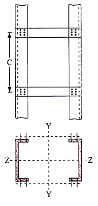
Battens shall be of plates, angles, channels or I-sections and at their ends shall be riveted, bolted or welded to the main components so as to resist simultaneously a shear Vb = (V1C)/N5 along the column axis and a moment M = (V1C)/2N at each connection.
Where,
V1 = Transverse shear force as defined above
C = Distance between center to center of battens, longitudinally
N = Number of parallel planes of battens, and
S = Minimum transverse distance between the centroid of the rivet/bolt group/welding connecting the batten to the main member.
A lacing system should generally conform to the following requirements:
- The compression member comprising two main components laced and tied should, where practicable, have a radius of gyration about the axis perpendicular to the plane of lacing not less than the radius of gyration at right angles to that axis.
- The lacing system should not be varied throughout the length of the strut as far as practicable.
- Cross (except tie plates) should not be provided along the length of the column with lacing system, unless all forces resulting from deformation of column members are calculated and provided for in the lacing and its fastening.
- The single-laced systems on opposite sides of the main components should preferably be in the same direction so that one system is the shadow of the other.
- Laced compression members should be provided with tie plates at the ends of the lacing system and at points where the lacing system are interrupted. The tie plates should be designed by the same method as followed for battens.
As per IS800 the following rules for the design of laced columns are as follows-
- The angle of inclination of the lacing with the longitudinal axis of the column should be between 40o to 70o.
- The slenderness ratio λ = le/γ of the lacing bars should not exceed 145.
- For riveted or welded lacing system, (L/γe, min) ≯ 50 or 0.7 times maximum slenderness ratio of the compression member as a whole, whichever is less.
Here, L = distance between the centers of connections of the lattice bars, and
γe, min= the minimum radius of gyration of the components of the compression member.
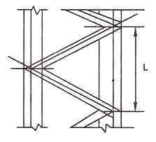
Iv. In bolted / riveted construction the minimum width of lacing bar shall be three times the nominal diameter of rivet/ bolt.
v. The lacing shall be designed to resist transverse shear equal to 2.5%of axial force in the columns .
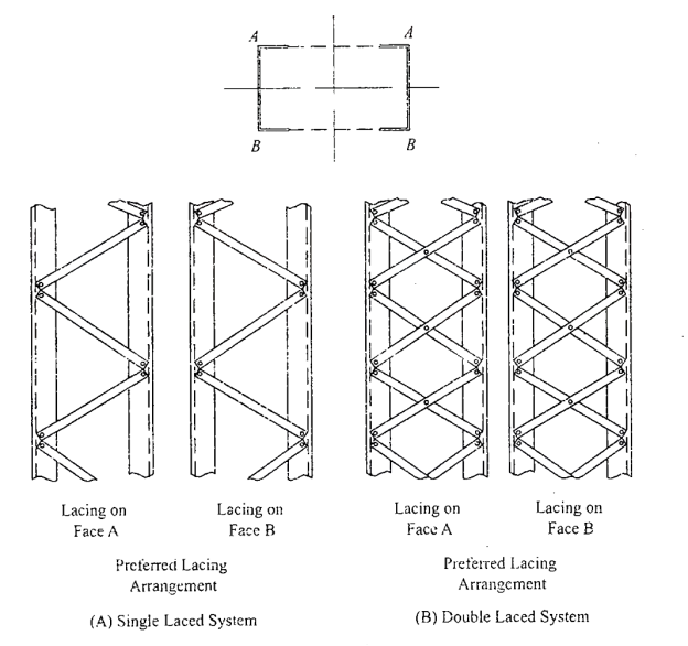
Vi. Laced compression members shall be provided with end tie plates.
Vii. The effective slenderness ratio of laced columns shall be taken as 1.05 times the actual maximum slenderness ratio .
Viii. Minimum thickness of lacing bars:
t ≮ l/40 , for single lacing;
t ≮ l/60, for double lacing
Where l = length between inner end rivets.
Connections-
- The riveted connections may be made in two ways, as shown in the figure (a) and (b).
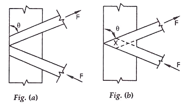
Minimum width of lacing bars in riveted connection should be according to the Table given below:
Nominal rivet diameter (mm) | 22 | 20 | 18 | 16 |
Width of lacing bars (mm) | 65 | 60 | 55 | 50 |
Lap Joint – Overlap should not be less than ¼ times thickness of bar or member, whichever is less.
Butt Joint – Full penetration butt weld or fillet weld on each side, lacing bar should be placed opposite to flange or stiffening component of main member.
Ex-Design a laced columns with two channels back to back of length 10m to carry an axial factored load of 1400KN. The column may be assumed to have restrained in position but not held in position at both ends?
Solution- assume fcd=135N/mm2
Area required =1400*1000/135=10370mm2
Try 2 ISMC350@413N/m
Area provided=2*5366=10732mm2
.rzz=136.6mm
Slenderness ratio=Le/r=1*10000/136.6=73.206
Since it is a laced column SR=1.05*73.206=76.87
Table 6.1
.fcd=152-6.87/10(152-136)=141N/mm2
Load carrying capacity-=10732*141=1513297N=1513.297kN>1400kN ok
Spacing between the channels=d
Ixx=2*10008*10000=200160000 mm4
Iyy=2[430.6*104+5366(d/2+24.4)2]
Equating Iyy to Ixx we get
200160000=2[430.6*104+5366(d/2+24.4)2]
(d/2+24.4)2=17848.3
d=218.4mm=220mm as shown in fig
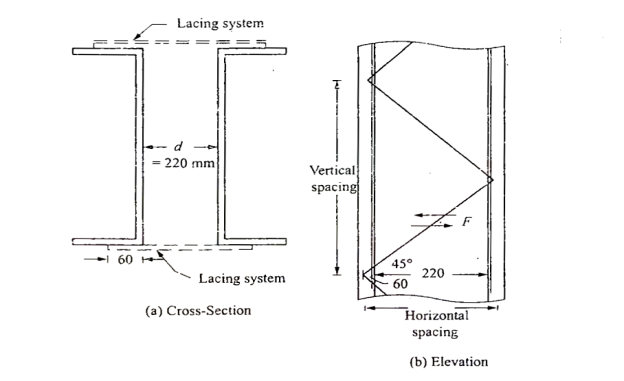
Lacing-let the lacing be provided at 45 degree to horizontal
Horizontal spacing of lacing=220+60+60=340mm(note60= gauge distance)
Hence vertical spacing =340tan 45*2=680mm
.least r of the channel=ryy=28.3mm
Le/r of the channel between lacing =680/28.3=24.03<50 ok
Transverse shear to be resisted by lacing stystem=2.5*1400*1000/100=35000N
Shear to be reisted by each lacing system=35000/2=17500N
Length of lacing=220+60+60)*1/cos45=480.83mm
Minimum thickness of lacing=1/40*480.83=12.02mm
Use 14mm flats
Minimum width of lacing if 20mm bolts are used=3*20=60mm
Use 60ISF 14
Sectional area=60*14=840mm2
.rmin=√60*143/12/60*14=4.041mm
SR=480.83/4.041=118.97<145 ok
Strength of 20mm shop bolt-
1- In single shear=0.78*3.14/4*202*(400/√3 *1.25)=45272N
Edge distance =60/2=30mm
Kb=30/3*22=0.4545
2- Strength in bearing =2.5Kb*d*t*fu/1.25=2.5*0.4545*20*10*400/1.25
=101808N
Therefore bolt value=45272N
No of bolts required= 17500/45272=0.387=1 bolt
Check for strength of lacing-
Le/r=118.97
A flat belong to class c
.fcd=94.6-8.97/10(94.6-83.7)=84.82N/mm2
Load carrying capacity in compression=84.82*60*14=71251N
Force in lacing =17500/sin45=24749N<71251N ok safe
Hence provide 60ISF 14 flats at 45 degree and connect them to centre of gravity of channels with one bolt of 20mm nominal diameter.
DESIGN OF BATTEN & CONNCETION OF BATTENING WITH MAIN COMPONENTS BY BOLT/WELD-
Compression members composed of two main components battened should preferably have these components of the same cross-section and symmetrically disposed about their X – X axis.
The battens should be placed opposite to each-other at each end of the member and at points where the member is stayed in its length, and should as far as practicable, be spaced and proportioned uniformly throughout.
The effective length of columns should be increased by 10 percent.
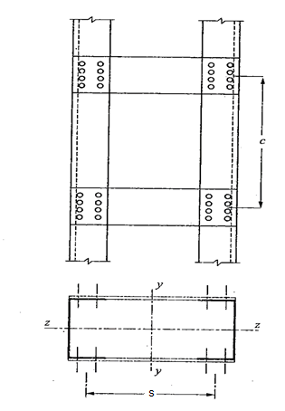
Design Details of Battens
- Spacing of batten C, from centre-to-centre of end fastening should be such that the slenderness ratio of the lesser main component, (C/γe, min) ≯ 50 or 0.7 times the slenderness ratio of the compression member as a whole about X – X axis (parallel to battens) whichever is less.
- The min. No. Of battens =4 so that the columns into min of 3 bays.
- Battens shall be plates , angles , channels, and at their ends shall be riveted bolted and welded.
- Effective depth of battens, d shall be taken as distance between end rivets or end welds.
d > ¾ a for intermediate batten
d > a, for end batten
d > 2b , for any batten
Where d = effective depth of batten
a = centroidal distance of members
b = width of members in the plane of battens.
- Thickness of battens, t > (lb/50)
Where, lb = distance between the innermost connecting line of rivets or welds.
5. Battens should be designed to carry bending moment and shear arising from a transverse shear,
V = 2.5 P/100
Where P = total axial load in the compression member.
Transverse shear V is divided equally between the parallel planes of battens. Battens and their connections to main components resist simultaneously a longitudinal shear.
V1 = V C/N S
And , moment M = (F C)/2N
Due to transverse shear V.
Where, C = spacing of battens
N= number of parallel planes of battens
S= minimum transverse distance between centroid of rivet group or welding.
The end connections should also be designed to resist the longitudinal shear force V1 and the moment M.
6. The effective slenderness ratio of battened columns shall be taken as 1.1 times the maximum actual SR of the column
For welded connection
- Lap < 4t
- Total length of weld at edge of batten < D/2
a + b+ c < D/2
Let t = thickness of batten
Length of continuous weld at each edge of batten < 1/3 of total length required.
Return weld along transverse axis of the column < 4t
Where, t and D are the thickness and overall depth of battens, respectively.
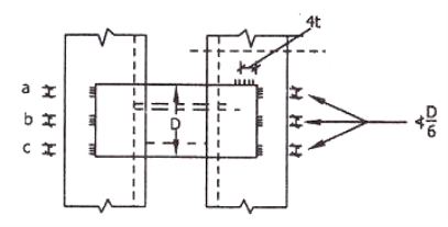
Example- design a battened column with two channels back to back of length 10m to carry an axial factored load of 1400kN. The columns assumed to have restrained in position but not in direction at both ends?
Solution=
Assume fcd=135N/mm2
Area required A= 1400*1000/135 =10370mm2
Try 2 ISMC 350@413 N/M with clear spacing 220mm
A= 2*5366=10732mm2
Rzz=136.6mm
SR= 1.1*10000/136.6 =80.52
Distance between centres of channel S= 220+60+60=340mm
Let C be the spacing of batten longitudinally
Radius of gyration of one channel = 28.3mm
Hence C/28.3 <50 i.e C<1415
Let us select C=1200mm
Vt= 25/100 *1400*1000 = 35000N
Vb= Vt C/N S = 35000* 1200/2*340 = 61765N
M= Vt C/2N=35000*1200/2*2=10500000N-mm
Size of battens-
Provide eff depth <268.8mm and also < 2*100mm
Provide 270 mm depth for end battens , overall depth = 270+ 2*edge distance (35)
=340mm
For intermediate batten it is < ¾*270mm and < 200mm
Provide depth =210mm
Overall depth=210+2*35=280mm
Thickness of battens<1/50*340
<6.8
Use 8mm thick plates.
Check for stress in batten plates-
Shear stress=61765/280*8=27.57 N/mm2 < fy/1.73*1.1 ok
Bending stress = 6M/td2 =6*10500000/8*2802
100.45<227.27 N/mm2 ok
Column bases, slab base, gusseted base, and moment resistant bases
The columns are supported at the column bases. The column bases transmit the column load to the concrete or masonry basis blocks.
The column load is unfold over massive location on concrete or masonry blocks. The depth of bearing stress on concrete or masonry is stored inside the most permissible bearing stress.
The protection of the shape relies upon up on balance of basis. The column bases need to be designed with utmost care and skill. In the column bases, depth of stress on concrete block is thought to be uniform.
The column bases will be of ok strength, stiffness and location to unfold the burden upon the concrete, masonry, different basis or different helps without exceeding the allowable strain on such basis below any mixture of the burden and bending moments.
The column bases are of types;
- Slab base
- Gusseted bases
- Slab base
The column give up is confronted for bearing over the complete area. The gussets (gusset plates and gusset angles) aren't supplied with the column with slab bases. The enough fastenings are used to hold the elements securely in plate and to withstand all moments and forces, apart from the direct compression. The forces and moments springing up all through transit, unloading and erection also are considered. When the slab by myself distributes the weight uniformly the minimal thickness of a square slab is derived as below;
Procedure
Step 1) Assume a suitable grade of concrete. Depending upon the grade of concrete used bearing strength of concrete is determine by 0.45fck
Step 2) The area of a slab base may be computed by
A= P/ bearing strength of concrete
Where,
A= area of base plate
P= Factored load
Step 3) A square base plate is generally provided. The side of the base plate may be worked out
L= B= 
Some designer feel that the projections of the base plate beyond column edges a and b are kept equal and these sides can be work out.
Using
( D+2b) x (bf+2a)= A
Where,
L= length of base plate in mm
B= width of base plate in mm
D= depth of column section in mm
Step 4) The intensity of pressure w from the concrete pedestal is determine by
W= P/A1
Where, w= intensity of pressure from concrete under the slab base
A1= Area of base plate provided in mm2
Step 5) The minimum thickness ts of the base plate is calculated by using

Step 6) Holding down bolts 2 or 4 in number and of 20 mm diameter are usually provided. When the base subjected to only axial compressive load two bolt will be enough.
Step 7) welded joint between the column and base plate is designed.
Step 8) Detailing
2. Gusseted base
Procedure
Step 1) Bearing strength of concrete is determined = 0.45 f
Step 2) Area of the base plate may be computed by,
A = P/0.45 fck
Step 3) The size of gusset base assumed
(i) Thickness: For bolted gusset base t <16 mm.
(ii) The gusset angle is chosen so as to accommodate two rows of bolts in the vertical leg and one row of bolt in the horizontal leg. Therefore an unequal angle section is provided.
(iii) The thickness of gusset angle should be same as thickness of gusset plate.
(iv) Width of base plate.
L = depth of section + 2 (thickness of gusset plate +
leg length of angle + over hang) (for bolted connections)
L = depth of section + 2x (thickness of gusset plate + overhang)
(for welded connections)
(v) Width of base plate
B = A/L
Step 4) The intensity of bearing pressure
W = P/A1
Where
A₁ = Area of base plate provided
Step 5) The thickness of the base plate is computed by equating the moment at the critical section to the moment of resistance of the gusset at that section.
B.M. At critical section
M = wc12/2(considering unit width)
Where
c.- Minimum over hang
Design bending moment at critical section M, 12

Now equating, M = Md


Where,
t= Total thickness including thickness of base plate and gusset angle (for bolted gusset base)
= Thickness of base plates (for welded gusset base)
W= Intensity of pressure from concrete under the slab faze.
C₁=Cantilever portion of base plate
Step 6) Holding down bolts 2 or 4 in numbers and of 20 diameter are usually provided.
Step 7) Design connection
Step 8) Detailing
Q.1 Design a slab base for the column consisting of ISMB 400@ 61.6 kg/m carrying an axial factored load of 450kN. Use M20 grade of concrete.
Solution:
- Area of base plate


2. Size of base plate
Provide 430 x 170 mm size of base plate
Area provide = 73100> A required
3. Intensity of pressure w from concrete pedestal
w = P/A provides


4. Thickness of base plate (ts)

Provides base plate of size 430 x 170 x 16 mm
Q.2 Design a slab base for a column ISHB 350 @ 67.4 kg/m carrying a factored load of 1000 kN. Also design the welded connection between slab base and column. Use concrete grade M20 and Steel of Fe410
Solution:
- Bearing Strength of concrete

2. Area of base plate

3. Size of base plate
Provide 410 x 310 size of base plate

4. Intensity of pressure w from concrete pedestal

Projection


5. Thickness of base plate

Thickness of flange of ISHB 350 @ 67.4 kg/m is 11.6 mm
Provide 410 x 310 x1 2 mm plate to carry load
6. Design of anchor bolts
Use a bolts of 20 mm diameter of 300 mm long to anchor the plates
7. Design fillet weld column is fixed over a base plate
Using fillet weld of column is fixed over a base plate
Total length available for welded

Strength of weld

Let a be the size of weld
Then effective area of weld = 0.7 x a x Le
Equating to the strength by assuming the size of weld 6 mm


Available effective length


Hence Provide 6 mm size of fillet weld
Q.3 Design the section of steel column and suitable base for an axial compressive factor load of 3000 kN. The effective length of column is 6 m The grade of concrete used for pedestal is M30.
Solution:
- Factored load P
P= 3000 KN
KL= 6000 mm
Fy = 250 MPa
Assuming Fcd = 200 MPa
2. Selection of section
Area of required = 
Provided built up section 2 ISLC 400 @ 45.7 kg/m with cover plate of 420 X6 mm shown in
Properties
A= 5825 mm^2
D = 400 mm
Bf = 100 mm
Tf = 14 mm
Tw = 8 mm
C = 23.6 mm
Izz = 11989.5 x 10 ^4 mm^4
Iyy= 460.4 x 10^4 mm^4
Area Provided
5825x2+2x420x6 = 16690 mm^2 > A required
3. Design strength (pd)
Slenderness ratio = 
Buckling class for built up section is C
Using table 9(c)
Design compressive stress
Fcd = 202.47 MPa
Design strength (pd) = Ae x Fcd = 16690 X 202.47 = 3379.2 kN
4. Design of slab base
As M30 grade concrete used for pedestal
Required area of base plate

Providing nominal cleat angle of 65 x 65 x 8 mm
Minimum width of base plate
2x65 + 420 = 550 mm
Length of base plate L = 460 mm
Area of base plate provided = 550 x 460
A1= 253000 mm^2 > Area Required
Bearing pressure of concrete on base plate

Projections


Thickness of base plate

Hence Safe
Provide base of size 550 x 460 x 24 mm Thick
Q.4 Design a slab base for the column consisting of ISWB 300 @ 48. 1kg/m carrying an axial factored load of 1100 KN. Design welded connection between column and base plate. Concrete of grade M20 is available.
Solution:
Design of slab base for column ISWB 300 @ 48.1kg/m
- Factored load P = 1100 KN
- Bearing strength of concrete
= 0.45 fck = 0.45 x 20 = 9 N/mm^2
3. Size of base plate

Provide size of base plate 410 x 310 mm
4. Thickness of base plate

Projections


Thickness of base plate

Provided 410 x310 x 16 mm plate for slab base
5. Design of welded connection
Length of weld available

Assuming size of weld 6 mm


Available effective length
= 1365.2 – 2 x 6 x12 = 1221.2 mm < Lw required
Unsafe
Hence provide 9 mm size of fillet weld for a 1200 mm length
Q. 5 Design a base plate for column of ISHB 250 @ 51.0 kg/m carrying a factored load of 650 KN. Assume that the column is supported on a concrete of grade M 25
Solution:
- Bearing strength of concrete
0.45 fck = = 0.45 x 25 = 11.25 MPa
Area of base plate

2. Size of base plate


3. Intensity of pressure w from concrete pedestal

Projections


4. Thickness of base plate

Thickness of flange of ISHB 250 @ 51 kg/m is 9.7 mm
Provide ts = 10 mm thick base plate
Provides base plate of size 310 x 310 x 10 mm
Plate to carry load safety
Q.6 Explain types of column bases and design the size of slab for a column ISHB 350 @ 67.4 kg/m supporting a factored axial compression of 1200KN consider grade of concrete as M20
Solution:
1.Geometrical properties of ISHB 350 @ 67.4 kg.m
h = 350 mm
Bf = 250 mm
Tf = 11.6 mm
8.3 mm
2.Size of base plate
Area required =

Select 420 x 380 mm size of base plate
Area provided= 420 x 380
= 15.96 x 10^4 mm^2 > A required
3.Bearing pressure an base plate

4. Thickness of base plate
Assume


Provide base plate of size 420 x 380 x 12 mm for slab base
References:
1. Design of Steel Structure, N Subramanian, Oxford University Press, New Delhi
2. Limit State Design in Structural Steel, M. R. Shiyekar, PHI, Delhi
3. Fundamentals of structural steel design, M L Gambhir, Tata McGraw Hill Education Private limited, New Delhi.
4. Structural Design in Steel, Sarwar Alam Raz, New Age International Publisher
5. Limit State Design of Steel Structure, V L Shah & Gore, Structures Publication, Pune