Unit – 2
DC Machines
They convert mechanical energy into electrical energy. The energy conversion is based on the principle of production of induced emf. The construction and working are explained below.
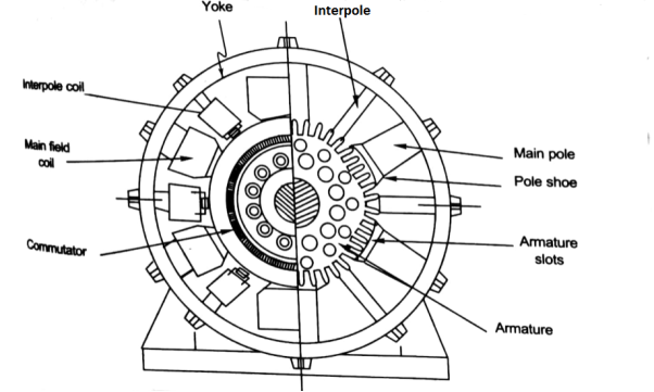
Construction – A simple generator is shown below, the essential parts of which are
- Yoke – It is the outer frame of machine which carries the magnetic flux produced by poles and also provides mechanical support to the poles. The yoke is generally made of cast steel or rolled steel.
- Pole shoes – They are made up of thin lamination of annealed steel, which are piled up under hydraulic pressure. They spread out the flux in the air gap. They reduce the reluctance as they have large cross-sectional area.
- Held coils –They are the copper wire which are wounded around the core, the flux is produced when the current passes through these coils.
- Armature core – It provides the low reluctance path to the flux through the armature. It carries the conductor coils and makes them to rotate, which in turn tells the magnetic flux produced. It is cylindrical in shape and made of circular steel sheets.
|
Fig 1 Cross Section of DC Machine
- Armature Windings – These windings are arranged in armature slots, the slots are lined with tough insulating material. The useful EMF is encouraged in these findings and is received across brushes.
- Commutator - It collects the current from armature and supplies to the load. It is cylindrical in shape. It periodically reverses the current direction between the rotor and external circuit. It is composed of multiple metal segments insulated from each other by thin layer of Mica. The number of segments is equal to number of armature coil.
- Brushes and bearings - The brushes are usually made of carbon or graphite. The main function of brushes is to collect current from commutator. They are housed in brush holders and mounted on a spindle. The number of brushes per spindle depends upon the magnitude of the current to be collected from commutator.
Key takeaway
They convert mechanical energy into electrical energy. The energy conversion is based on the principle of production of induced emf
Generating Action
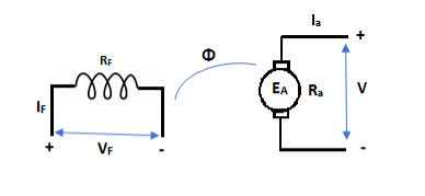
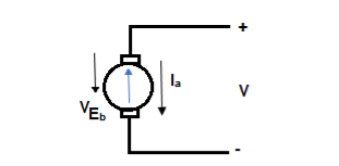
The basic circuit model for a dc machine is shown below:
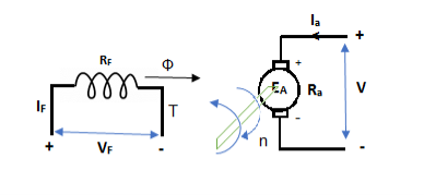
Fig 2 Generating Action The machine operates in generating mode when the armature current is in the direction of induced emf Ea. V = Ea – Ia Ra Ea> V Pmech = Ea Ra = Pelect The output power, P0 = VIa EaIa – VIa = Ia2 Ra |
|
Fig 3 Generation of Torque in armature
Motoring Action
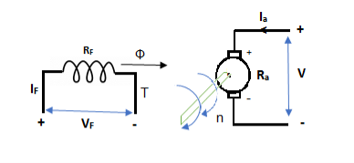
In this mode, the armature current Ia flows opposite to the emf induced i.e. Ea. The basic circuit showing this mode is below:
Fig 4 DC Motor (Ea – Eb) is called as back emf here as it opposes the armature emf. V = Ea + IaRa Electrical power connected to mechanical form Pelec / net = EaIa Power input, Pi = V Ia V Ia – EaIa = Ia2Ra = armature copper loss.
Key takeaway The back emf is given as Eb = In this mode, the torque of electromagnetic origin is in opposite direction of rotation of armature. [Pmech]gross = Shaft power = [Pmech]net + Rotational loss.
|
The average coil emf
Wm = armature speed rad/s. As parallel path emf is equal to armature emf,
Np = turns / parallel path = Z = Total armature conductors A = Number of parallel paths.
n = armature speed rpm |
Key takeaway
The EMF equation is
|
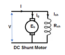
- Shunt motor – In this, the field winding is connected in parallel with the armature.
Fig 5 DC Shunt Motor The input current I = Ia + Ish For field winding, V = IshRsh For armature, V = Eb + IaRa Ia = armature current Ish = shunt field current V = input voltage I = Input current Power Input = Mechanical power + losses in armature + losses in field VI = Pmech + Ia2Ra + Ish2Rsh Pmech = VI – VIsh - = Ia2Ra = V (I – Ish) – Ia2Ra = VIa - = Ia2Rsh = (V – IaRa)Ia Pmech = EaIa |
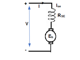
- Series motor – In this, the field winding is connected in series with the armature.
Fig 6 DC Series Motor Ise = series field current I = Ia = Ise V = Ea + I(Ra + Rse) VI = EaI + I2(Ra + Rse) VI = Pmech + I2 Ra + I2Rse Pmech = Ea I |
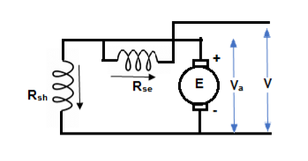
- Compound Motor – It is a type of dc motor which had both shunt and series field windings.
Fig 7 Compound Motor V = Ea ± Ia (Ra + Rse) IL = Ia ± IF They are basically of 2 types- long shunt and short shunt.
Key takeaway For Shunt Motor The input current I = Ia + Ish For field winding, V = IshRsh For Series Motor Ise = series field current I = Ia = Ise For Compound Motor V = Ea ± Ia (Ra + Rse) IL = Ia ± IF |
In a DC motor when the armature rotates the conductors also rotate and hence cut the flux. According to the lower electromagnetic induction, the induced EMF is in the opposite direction (by Fleming’s Right hand rule) to the applied voltage. As it has opposite direction so it is referred to as back EMF (Eb).
|
Fig 8 Equivalent Circuit with Back EMF
This back emf Eb is like battery put across main supply. This back emf is given as
|
Motor Torque
Power developed = Ta × 2πN W As electrical power is converted to mechanical =EbIb So, power developed = Power converted Ta × 2πN = EbIb
We can also conclude from the above eqn.
For series,
For shunt,
The torque doing useful work is called as shaft torque, Tsh. Motor output =Tsh × 2πN
Due to iron and friction losses in motor Ta – Tsh difference torque exists called as lost torque.
|
Key takeaway
For series,
For shunt,
For Shunt
|
Examples
Q. 1 A 4 pole dc generator runs at 650 rpm and generates emf of 220V. The armature is wave wound and has 790 conductors. If total flux/pole is 0.0145 Wb in each pole, find leakage coefficient.
Sol.
Leakage coefficient = Working flux is given as
A = 2 for simple wave winding.
Leakage coefficient = |
Q. 2A 4 pole lap wound dc shunt generator has a useful flux per pole of 0.05 Wb. The armature winding consists of 200 turns each of 0.06 u ohm resistance. Calculate the terminal voltage when running at 900 rpm with armature current of 50 A.
Sol
. Terminal voltage V =Ea – Ia Ra Ia Ra = 50×Ra.
Z = 200×2=400 (each turn has two sides). N = 900 rpm
Total resistance of 200 turns = 200 × 0.004 = 0.8 ohm As there are 4 parallel paths, so resistance of each path = 0.8/4 = 0.2 ohm There are 4 resistances in parallel of each of 0.2 ohm Ra = 0.2/4 = 0.05 ohm Ia Ra = 50×0.05 = 25 V V = Ea – Ia Ra = 300 – 25 = 275 V |
Q. 3 A 220 V 4 pole wave wound dc series motor has 780 conductors on its armature. It has armature and series field resistance of 0.75 ohm. The motor takes a current of 30A. Find the speed and gross torque developed if flux/pole is 20 mWb?
Soln.
Back emf, Eb = V – IaRa = 220 – (30×0.75) = 197.5 V 197.5 = 20 × 10-3 ×780×N×0.75 N = 16.88 ≈ 17
Ta = 158.97 Nm. |
Q. 4 A 4 pole, 210 V shunt motor has 450 lap wound conductor. It takes 32 A from supply mains and develops output power of 4.5 kW. The field takes 1 A. The armature resistance is 0.09 ohm and flux per pole is 30 mWb. Calculate speed and torque.
Sol
Ia = 32-1 = 31 n Eb = V – Ia Ra = 210 - (0.09×31) = 207.21 V
N = 920.9 rpm
|
Q. 5 A 220 V, dc shunt motor has an armature resistance of 0.3 ohm and field resistance of 105 ohm. At no load speed is 1200 rpm and armature current are 2.3 A on application of rated load speed drops to 1120 rpm. Find the current and power input when motor delivers rated load.
Sol.
N1 = 1200 rpm Eb1 = 220 – (0.3×2.3) = 219.31 V N2 = 1120 rpm Eb2 = 220 – 0.3 Ia2
Ia2 = 37.93 A Line current = Ia2 + Ish = 37.93 + (220/105) = 40 A Power input = 220 × 40 = 8800 W
|
Q.6 A 230 V shunt motor runs at 1000 rpm at no load and takes 6A. The total armature resistance is 0.2 ohm and field resistance is 210 ohm. Calculate the speed when loaded and taking 40 A. Assume flux constant.
Soln.
|
Q. 7 The armature resistance of a 15 kW, 230 V series motor is 0? 1 ohm, the brush voltage drop is 3 V and series field resistance is 0.05 ohm. The motor takes 60 A speed is 600 rpm. Calculate speed when current is 100 A.
Soln.
Φ1 Φ2
N2=350.22 rpm |
Q.8 A 230V DC Shunt motor takes 4A at no load when running at 600 rpm. The field resistance is 100 ohms. The resistance of armature at standstill gives a drop of 6V across armature terminals when 10A were passed through it. Find i) Speed at no load (ii) Torque. Normal input of motor is 6kW
Sol
i)Speed Ish= F.L Power=6000 F.L line current= Ia=26.08-2.3=23.78A Ra=
N=566.2 rpm
ii)Torque
|
The characteristic curve of DC Motor can be described by the below mentioned relationships
- Torque and Armature Current (Electrical characteristics)
- Speed and Armature Current
- Speed and Torque (Mechanical characteristics)
Now briefly describing the above-mentioned characteristics for DC Series Motor
Characteristics for DC Series Motor:
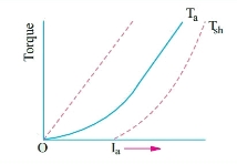
a) Torque and Armature current characteristics: As we have already seen that armature torque Ta is proportional to the product of flux linked and the armature current
Ta α φ Ia
Since φ α Ia
Ta= I2a
As Ta is proportional to the square of armature current, the curve is Parabolic as shown below.
|
Fig 9: T v/s Ia characteristics
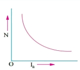
b) Speed and armature current characteristics: As we know speed (N) is related to back emf as
N α Eb/φ
but φ α Ia .
So, as the value of Ia increases the vale corresponding value of φ also increases. So, N αEb/ Ia
As the speed increases the value of current decreases (inversely proportional). For various values of load current there is very small change in the value of Eb, hence can be neglected here. The curve is shown below.
|
Fig 10: Speed verses Armature current characteristics
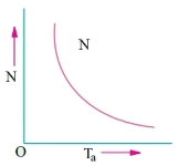
c)Speed and Torque characteristics: As Ta α φ Ia and φ α Ia , but N αEb/ Ia .So it can be easily concluded that speed and torque are inversely proportional. Hence when speed is high torque is low and vice versa. The curve is shown below.
|
Fig 11: Speed verses Torque characteristics
Key takeaway
For speed torque characteristics Ta α φ Ia and φ α Ia, but N αEb/ Ia
For speed armature characteristics N α Eb/φ but φ α Ia.
For Torque armature characteristics Ta= I2a
Characteristics of DC Shunt Motor
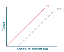
a) Torque and Armature current characteristics: As relation between torque and armature current is Ta α φ Ia, assuming φ to be practically constant. So, Ta α Ia and the characteristics are linear as shown below.
|
Fig 12: Torque versus Armature current
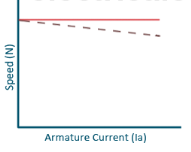
b) Speed and Armature current characteristics: N α Eb/φ, for φ to be practically constant N α Eb. But both Eb and φ decrease with increasing load. The drop varies from 5 to 15% of full load speed. As Eb decreases more than φ speed decreases.
|
Fig 13: Speed verses Armature current characteristics
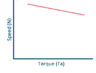
c)Speed and Torque Characteristics: From above to characteristics, curve for this shown below.
|
Fig 14: Speed verses Torque characteristics
Key takeaway
Torque armature characteristics are linear
Sol:
Ish=250/250=1A Ia1=4-1=3A Ia2=50-1=49A Eb1=250-3*0.4=248.8V Eb2=250-49*0.2=240.2A
N2=898rpm |
Que) The speed of a 37.3kW series motor working on 500V supply is 600 rpm at full load and 90% efficiency. If the load torque is made 250 N-m and a 5ohm resistance is connected in series with the machine, calculate the speed at which the machine will run. Assume armature and field resistance of 0.5ohm?
Sol:
Load torque in first case T1=37300/2 Input current Ia1=37300/0.9*500=82.9A T2=250 N-m. So, finding Ia2 For series motor T α φ Ia α Ia2 T1 α
Eb1=500-(82.9*0.5) =458.5V Eb2=500-53.79(5+0.5) =204.11V
|
All motors should be started with external resistance in armature circuit to limit the starting current to safe values, if not then there can be a risk of high value of torque which can cause mechanical shock to the shaft and it can also cause heavy sparking at the brushes which can damage the commutator and brush gear. At the time of starting the induced emf of motor is zero. In case of direct start of motor, the toque is much higher and motor starts quickly, which saves the energy and reduces temperature rise. Maximum allowable starting current cannot be more than 1.5 to 2.0 times the rated value. For variable speed the starting of motor has no problem.
The connection diagram of DC Shunt motor starter is shown below. It is the manual starter.
|
Fig 15: DC Shunt motor starter
In shunt motor starting to maintain high torque the starting resistance is arranged in steps. When starter is in ON position the starting resistance is cut out. The handle can go back to OFF position when there is no field current and in case of overload when the contact of relay at armature current is above certain value. Modern industries use push button type automatic starters. As shown in the figure below
|
Fig 16: Shunt motor starting
They have automatic relays that short the section of starting resistors when the armature current has dropped to a pre-set value.
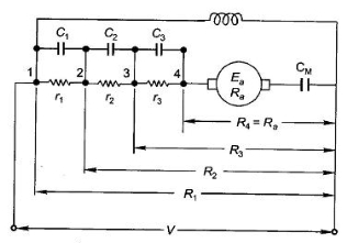
Calculation of starter step for DC Shunt Motor
From above figure when the stud is moved to point 1, the current I1 is reached. I1 = V/R1 When the speed of motor increases the current decreases and the back emf rises. The value of current I2 is given as I2=
I1=
For k stud starter
Hence
After calculating starter step i)Find R1 ii)Find number of steps k iii)Find R1, R2…….
Basically, there are three types of starters
|
For series motor:
Basically a 2-point starter is used in DC series motor. As we already know that Eb is given as
Eb= |
V-Eb=IaRa
when Eb=0. From above equation Ia at the moment of starting can be given as Ia= V/Ra.
The Ra is very low in practically, generally about 0.3 to 0.8 ohms. Therefore, a large current flow through the armature during starting. This current is large enough to damage the armature circuit. This also causes blowing of fuse and dip in terminal voltage of other equipment connected locally. This is the main reason why starters are used in DC motors.
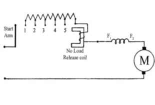
|
Fig 17: Two-point starter
When the starter arm is moved to 1, it gets attached to maximum resistance connected in series with armature during starting, and decreases gradually as it moves towards right. A DC series motor must always be started on load. If started on No load the motor will attain a dangerously high speed.
For Shunt motor:
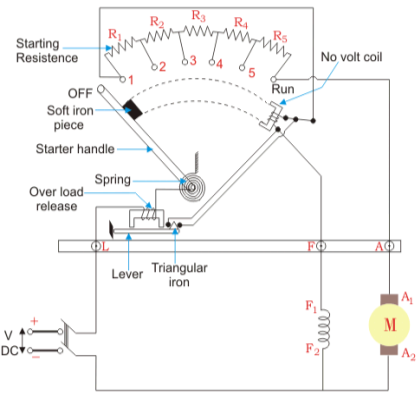
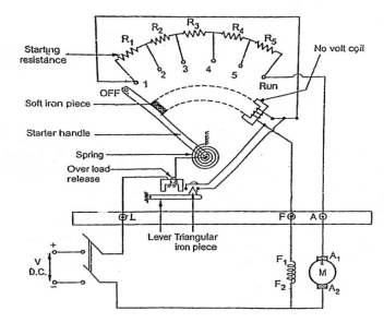
A 3-point starter is used for starting a DC shunt motor. The starter is shown below
|
Fig 18: 3-point starter
The arm of stud is moved to 1, to start the motor. The complete resistance added to armature winding. Through No-volt-coil (NVC) the field winding also gets full supply. So, the motor develops torque and starts rotating with full starting resistance. When the stud is moved further RUN position is achieved. In this position a soft iron piece is attached to starter arm. Therefore, will stay in the RUN position against the spring tension. In case of overload the armature winding will draw excess current and may get damaged. So, to protect from this damage the over load release coil will be short circuited and will demagnetise NVC. Which will eventually turn off DC motor.
Disadvantages of 3-point starter:
The field current is reduced when a large resistance is connected to increase the speed. But the field winding and NVC are connected in series, the current through NVC decreases. This may cause the starter to move to OFF position, which may affect the working of motor. To overcome this drawback, we have four-point starter.
Four-point starter:
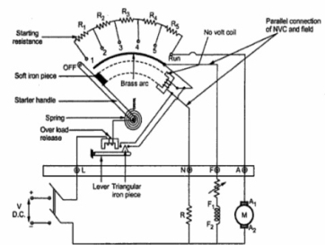
In this the NVC coil is connected independently across the supply voltage instead of connecting it in series with the motor field winding.
|
Fig 19: Four Point starter
When the arm is brought to position 1 current flows through armature winding, the field winding will also get full supply. In this the field winding and NVC are isolated from each other. Hence, any change in If will not affect NVC like in three-point starter. When started arm is brought to the RUN position, the armature of the dc motor will run at its full speed and remain connected to the supply through the starter arm. In case of overload, the OLR terminal will be short circuited to the NVR coil to release the starter arm to the OFF position.
Key takeaway
At the time of starting the induced emf of motor is zero. In case of direct start of motor, the toque is much higher and motor starts quickly, which saves the energy and reduces temperature rise.
Que) A starter required for a 220V shunt motor. The maximum allowable current is 45A and the maximum current is about 35A. Find the number of sections of starter resistance required and the resistance of each section. The armature resistance of motor is 0.4 ohm?
Sol:
I1=45 A , I2=35 A
R1= As
As we already know R1=4.44Ω R2= R3= r1= R1- R2=2.01 r2= R2- R3=1.1 Similarly r3=0.60 |
Series Motor: They are used in Electric locomotives, Cranes, Hoists, Conveyors and cars.
Shunt Motor: They are used for Blowers, Fans, centrifugal pumps, for driving constant speed line shafting lathes.
Reference:
1) Basic Electrical Engineering, S.N. Singh, PHI, Learning Private Limited.
2) A Text Book Of Electrical Technology, B. L. Tharaja and A. K. Tharaja, S. Chand
Publication (Volume II & III)
3) Electrical Machines M. N. Bandyopadhya, PHI, Learning Private Limited.
4) Electrical Machines, Ashfaq Husain, Dhanpatrai Company, 4th edition.
5) Basic Electrical Engineering, D.C. Kulshreshtha, revised 1st edition, Tata Mc-Graw Hill education pvt. Ltd.
6) Generation of Electrical Energy- B. R. Gupta 4th Edition S Chand Publication
7) Testing Commissioning Operation & Maintenance Of Electrical Equipment – S. Rao Khanna Publication
