Unit – 4
AC motor
The fundamental principle of induction machine is the creation of rotating and sinusoidally distributed magnetic field in the air gap. Three phase balanced power supply is fed to the three-phase stator winding creates a synchronously rotating magnetic field. Due to relative speed between rotating flux and stationary conductors, an emf is induced. The frequency to induced emf is same as supply frequency.
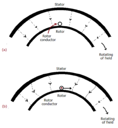
As shown in below figure a, the stator field is assumed to be clockwise. The relative motion of rotor w.r.t stator is anticlockwise. From Right-hand rule, the direction of induced emf in rotor is outwards. By the effect of combined field as shown in fig b the rotor experiences a force tending to rotate it in clockwise direction. Hence rotor rotates in the same direction as the stator field.
|
Fig 1 Rotating Field
The speed of this rotating field is called synchronous speed. If the rotor is initially stationary, its conductors will be subjected to a changing magnetic field, inducing current in the short-circuited rotor at the same frequency. The interaction of air gap flux and rotor mmf produces torque. At synchronous speed rotor cannot have any torque.
Key takeaway
The speed of this rotating field is called synchronous speed. If the rotor is initially stationary, its conductors will be subjected to a changing magnetic field, inducing current in the short-circuited rotor at the same frequency
There are two main parts of induction motor:
- Stator
- Rotor
Stator:
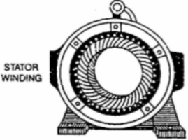
It is stationary part of induction motor. It has number of stampings. It is wound with three phase winding which is fed from 3-phase supply. The number of poles here are defined, they are selected according to the speed required. If required speed is greater than we need lesser number of poles. The stator produces an alternating flux when fed with 3-phase supply which revolves with synchronous speed (Ns = 120f / P). The synchronous speed is inversely proportional to number of poles.
|
Fig 2: Stator
Rotor: It is rotating part of induction motor. There are two types of rotor
Squirrel cage rotor:
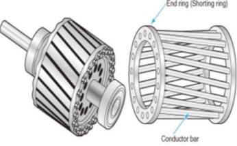
The rotor consists of a cylindrical core with parallel slots for carrying the rotor conductor. Each slot has one copper or aluminium bar. Each end of all bars is joined with metal ring. The entire construction resembles a squirrel cage. The rotor is not connected electrically to the supply it has induced current from stator. Almost 90% of induction motors are squirrel cage type. But is has a disadvantage of low starting torque, because the rotor bars are permanently short-circuited.
|
Fig 3 Squirrel cage rotor
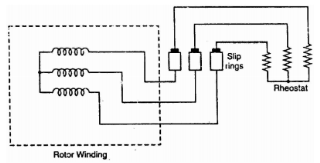
Phase-wound rotor: It has laminated cylindrical core and the windings are uniformly distributed in the slots which are usually star connected. The other three winding terminals are brought out and connected to three insulated slip rings mounted on shaft with brushes resting on them. The three brushes are connected to a 3-phase star-connected rheostat as shown in Figure below.
Fig 4: 3-phase star connected
At starting, the external resistances are included in the rotor circuit to give a large starting torque. These resistances are gradually reduced to zero as the motor runs up to speed. The external resistances are used during starting period only. When the motor attains normal speed, the three brushes are short-circuited so that the wound rotor runs like a squirrel cage rotor.
Key takeaway
The stator is stationary part of machine and rotor is the rotating part.
The rotor can never have same speed as that of stator. If it occurs then there will not be relative speed between the two, hence no rotor emf, no rotor current and so no torque to maintain rotation. Due to this reason speed of rotor is always less than the stator field. The difference between the synchronous speed Ns and the actual speed N of the rotor is called as slip.
% slip s= Therefore, rotor speed N=Ns(1-s). |
Synchronous Speed and frequency of rotor:
When rotor is stationary its frequency is same as the supply frequency. But when rotor revolves its frequency depends upon the slip-speed. Let frequency of rotor current be f’ Ns-N= But Synchronous Speed Ns=
Rotor current have same frequency =
|
Production of torque
The torque developed at the moment when motor starts is called as starting torque. As we already know the motor torque Ta α φ Ia. An induction motor develops gross torque Tg due to gross rotor output Pm. Then in terms of rotor input
Tg= In terms of rotor output the gross torque is
Tg= Due to rotor friction and windage losses the shaft torque Tsh is less than Pm
Tsh=
Tg
Tsh
For induction motor the torque is also proportional to the product of flux per stator pole and the rotor current, in addition to the power factor.
|
Starting Torque
T α φ I2 cos φ2
Or
T=k φ I2 cos φ2 I2=rotor current at standstill φ2=angle between rotor emf and rotor current E2=rotor emf at standstill. Also, E2 α φ So, T α E2I2 cos φ2 T=k1 E2I2 cos φ2 The starting torque Tst= k1 E2I2 cos φ2 From above section we know, Tst= k1 E2 . For supply voltage constant , flux and E2 both are constant Tst= k1= Therefore, Tst= |
Torque-Slip Relation:
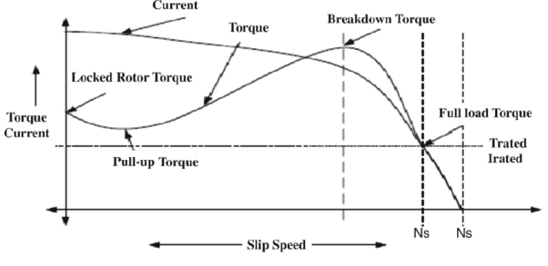
The torque slip characteristics is shown below. For low value of slip the curve is approximately a straight line. As slip increases the torque also increases and becomes maximum when s= R2/X2. This torque is called pull-out or breakdown torque Tb. From above section we already know T= T α When slip increases more with motor load R2 becomes negligible. So, for large value of slip
T α |
Speed Torque characteristics:
i) F increases, N increases, Tmax decreases.
ii) V increases, Tmax increases.
|
Fig 5(a) Speed Torque Characteristics
If the above two features are combined, we see that speed increases and torque kept same. If frequency is increased up to certain level and keeping voltage constant the motor speed increases and torque decreases. But when supply frequency is kept same and voltage is increased, then the motor characteristics in this case are stretched and the value of Tmax increases.
- Effect of Rotor resistance on Speed Torque characteristics
|
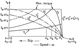
From above equation slip is directly proportional to rotor resistance. Hence speed decreases. This method is applicable to wound rotor induction motor.
|
Fig 5 (b): Torque speed characteristics
.
At the normal operating condition, the slip increases with increasing torque so there is curve is linear. For a fixed load curve, the speed is downward from n1 to n4. From this figure we can also obtain the maximum torque at the starting of the resistance r2”. So, this method has an advantage of achieving maximum torque at the starting period.
But the maximum torque is independent of the rotor resistance as per the equation,
|
Key takeaway
Tg=
Tg |
Examples
Sol:
a) P=2n=2*5=10 poles Total number of slots= 5 slots/pole/phase * 10 poles * 3-phase =150 a) Ns= |
Que) A 3-phase induction motor is wound for 5 poles and is supplied from 50 Hz. Calculate a) synchronous speed b) rotor speed when slip is 4% c) rotor frequency when rotor runs at 500 rpm?
Sol:
a) Ns= b) Rotor speed N=Ns(1-s) =1200(1-0.04) =1152 rpm c) When rotor speed is 500 rpm, slip s=(Ns-N)/Ns= (1200-500)/1200=0.58 rotor current frequency f’=sf=0.58x50=29.17 Hz |
Que) A 3-phase, 50 Hz,3-pole induction motor has a slip of 4%. Calculate a)speed of rotor. B) frequency of rotor emf. If the rotor as a resistance of 2ohm, and standstill reactance of 4ohm, calculate the power factor c) at standstill and d) at a speed of 1200rpm?
Sol:
Ns=
R2=2ohm, X2=4ohm Z2=R2+jX2=2+j4=4.47
slip at speed 1200rpm s= Rotor impedance at slip s=0.4 is Z2s=R2+jsX2=2+jx0.4x4=2.56
|
Sol:
Standstill emf/rotor phase=70/ Rotor impedance/phase= Rotor current/phase=40.4/5.09=7.92A Power factor cosφ=0.99 |
Que) A 3-phase induction motor star connected rotor has an induced emf of 70volts between slip rings at standstill on open circuit. The rotor has a resistance and reactance per phase of 1ohm and 5ohm respectively. Calculate current/phase and power factor when slip rings are connected to star connected rheostat of 2ohm?
Sol:
Rotor resistance/phase=2+1=3 ohm Rotor impedance/phase= Rotor current/phase= (70/ Cosφ=3/5.83=0.514 |
Que) A 6-pole, 3-phase induction motor operates from a supply whose frequency is 50Hz. Calculate i) Speed at which the magnetic field of stator is rotating. ii)speed of rotor when slip is 4%. iii)frequency of rotor current when slip is 3%?
Sol: i) Stator revolves at synchronous speed. So, Ns=120f/P=120 x 50/6=1000rpm
ii)rotor speed N=(1-s) Ns = (1-0.04) x 1000=960rpm
iii)frequency of rotor current f’=sf=0.03 x 50=90rpm
They are employed in lifts, cranes, hoists, large capacity exhaust fans, driving lathe machine, crushers, oil extracting mills and textile.
Split phase Induction Motor:
|
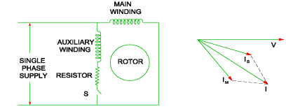
Fig 6 Split phase IM
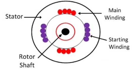
For highly resistive winding the current is almost in phase with the voltage and for highly inductive winding the current lag behind the voltage by large angle. The starting winding is highly resistive so, the current flowing in the starting winding lags behind the applied voltage by very small angle and the running winding is highly inductive in nature so, the current flowing in running winding lags behind applied voltage by large angle. The resultant of these two currents is IT. The resultant of these two currents produces rotating magnetic field which rotates in one direction. In split phase induction motor, the starting and main current get splitted from each other by some angle so this motor got its name as split phase induction motor.
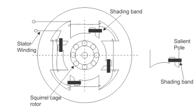
- When flux change from zero to positive maximum the copper band is short circuited and maximum current flows through it. This current produces its own flux. This flux opposes the main flux. So, in non-shaded part there is non-uniform distribution of flux casing the magnetic axis to shift in middle of the non-shaded part.
- When flux is still at its maximum and very less induced emf in the shaded portion. The main flux is not affected by the induced emf and hence, uniform flux remains.
- The flux the decreases from maximum positive to zero, the current is high. The copper band is short circuited and maximum current flows through it. This current produces its own flux. This flux opposes the main flux. So, in shaded part there is non uniform distribution of flux casing the magnetic axis to shift in middle of the shaded part.
|
Fig 7 Shaded Pole Induction Motor
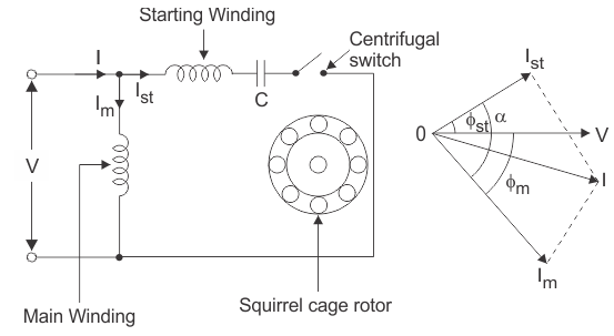
Capacitor start IM and Capacitor start capacitor run IM: These two motors have same working so discussing them together. In induction motor there is no rotating flux so the motor cannot be self-started. So, a phase difference is being produced to get the rotating magnetic field. A capacitor is used to create a phase difference in this case.
|
Fig 8 Capacitor Start IM
As the figure above shows we have main winding and starting winding. The capacitor is connected with the starting winding. The current Ist through the capacitor leads the voltage by some angle. The large phase difference between main winding current and starting winding current produces a resultant current I. This I generate rotating magnetic field.
These motors produce very high starting torque. In capacitor start induction motor, the centrifugal switch is provided so as to disconnect the starting winding when the motor attains a speed up to 75 to 80% of the synchronous speed but in case of capacitor start capacitors run induction motor there is no centrifugal switch so, capacitor remains in the circuit and helps to improve the power factor and the running conditions of single-phase induction motor.
Key takeaway
The types of IM are Split phase, Shaded Pole, Capacitor start IM and Capacitor start capacitor run IM
A Single-Phase Induction Motor consists of a single-phase winding which is mounted on the stator of the motor and a cage winding placed on the rotor. A pulsating magnetic field is produced, when the stator winding of the single-phase induction motor shown below is energized by a single-phase supply.
|
Fig 9 1-phase IM
The word Pulsating means that the field builds up in one direction falls to zero and then builds up in the opposite direction. Under these conditions, the rotor of an induction motor does not rotate. Hence, a single-phase induction motor is not self-starting. It requires some special starting means.
If the 1 phase stator winding is excited and the rotor of the motor is rotated by an auxiliary means and the starting device is then removed, the motor continues to rotate in the direction in which it is started.
The performance of the single-phase induction motor is analysed by the two theories. One is known as the Double Revolving Field Theory, and the other is Cross Field Theory. Both the theories are similar and explain the reason to produce torque when the rotor is rotating.
Double Revolving Field Theory of Single- Phase Induction Motor
The double revolving field theory of a single- phase induction motor states that a pulsating magnetic field is resolved into two rotating magnetic fields. They are equal in magnitude but opposite in directions. The induction motor responds to each of the magnetic fields separately. The net torque in the motor is equal to the sum of the torque due to each of the two magnetic fields.
The equation for an alternating magnetic field is given as
b(α) = β max sin w t cos α -----------------------(1)
where βmax is the maximum value of the sinusoidally distributed air gap flux density produced by a properly distributed stator winding carrying an alternating current of the frequency ω, and α is the space displacement angle measured from the axis of the stator winding.
sinA cosB = ½ sin(A-B) + ½ sin(A+B)
So, the equation (1) becomes
b(α) =1/2 β max sin (w t- α) + ½ β max sin (w t+ α) ------------(2)
The first term of the right-hand side of the equation (2) represents the revolving field moving in the positive α direction. It is known as a Forward Rotating field. Similarly, the second term shows the revolving field moving in the negative α direction and is known as the Backward Rotating field.
The direction in which the single -phase motor is started initially is known as the positive direction. Both the revolving field rotates at the synchronous speed. ωs = 2πf in the opposite direction. Thus, the pulsating magnetic field is resolved into two rotating magnetic fields. Both are equal in magnitude and opposite in direction but at the same frequency.
At the standstill condition, the induced voltages are equal and opposite as a result; the two torques are also equal and opposite. Thus, the net torque is zero and, therefore, a single- phase induction motor has no starting torque.
Application
These are used in low power applications and widely used in domestic applications as well as industrial. And some of those are Pumps, Compressors, Small fans, Mixers, Toys, High speed vacuum cleaners, Electric shavers, Drilling machines
Key takeaway
At the standstill condition, the induced voltages are equal and opposite as a result; the two torques are also equal and opposite. Thus, the net torque is zero and, therefore, a single- phase induction motor has no starting torque.
Reference:
1) Basic Electrical Engineering, S.N. Singh, PHI, Learning Private Limited.
2) A Text Book of Electrical Technology, B. L. Tharaja and A. K. Tharaja, S. Chand Publication (Volume II & III)
3) Electrical Machines M. N. Bandyopadhya, PHI, Learning Private Limited.
4) Electrical Machines, Ashfaq Husain, Dhanpatrai Company, 4th edition.
5) Basic Electrical Engineering, D.C. Kulshreshtha, revised 1st edition, Tata Mc-Graw Hill education pvt. Ltd.
6) Generation of Electrical Energy- B. R. Gupta 4th Edition S Chand Publication
7) Testing Commissioning Operation & Maintenance Of Electrical Equipment – S. Rao Khanna Publication
