Unit - 1
Important Vector Quantities
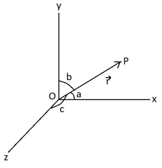
As the name suggests, it is a vector, which signifies the position of a body (or a point) with respect to the origin (or with respect to a certain point).
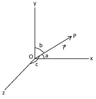
Vector r is the position vector of the point P with respect to the origin O and a, b, c are the angles with the x, y and z axis
So, r = r cos a i + r cos b j + r cos c kis the position vector of point P
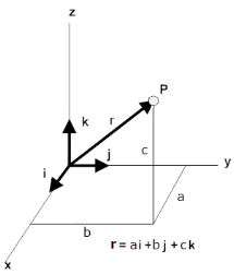
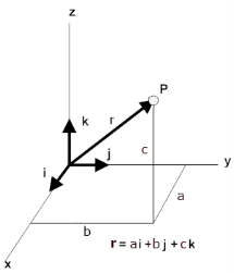
A convenient way to specify the position of an object is with the help of a coordinate system. We choose a fixed point, called the origin and three directed lines, which pass through the origin and are perpendicular to each other. These lines are called the coordinate axes of a three-dimensional rectangular (Cartesian) coordinate system and are labelled the x-, y-, and z-axis. Three numbers with units specify the position of a point P. These numbers are the x-, y-, and z-coordinates of the point P. The coordinates of the point P in the diagram to the right are (a, b, c).
The coordinates of the point P are the components of the position vector. A unit vector pointing in the x-direction has a x-component of 1 and y- and z- components of zero. It is denoted by i. Similarly, a unit vector pointing in the y-direction is denoted by j, and a unit vector pointing in the z-direction is denoted by k. Unit vectors are direction indicators.
The components of any vector add up to form the vector itself.
The position vector of a point P with coordinates (a, b, c) may be written in terms of its components as
r = ai + bj + ck.
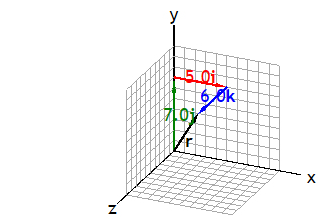
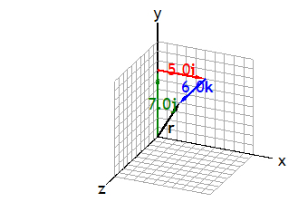
The magnitude of the position vector is its length r. It depends on the choice of the origin of the coordinate system. It is the straight-line distance of P from the origin. Below is a 3D representation of a position vector r = ai + bj +ck
The turning effect produced by a force on the body on which it acts is called as Moment.
Moment of force about any point is the product of magnitude of force and perpendicular distance of force from the point about which moment is to be taken.
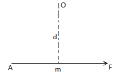
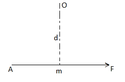
Let force F is applied at point A as shown & O is any point about which we want to take moment.
Thus from point O, draw OM line perpendicular to the line of action of force.
OM = d = Perpendicular distance between Force & point O.
Moment = M = F x d
Graphical representation of Moment:
- Select suitable scale to locate the force graphically.
- Draw a line parallel to line of action of force. Length of this line can be calculated from selected scale.
 -
-
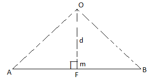
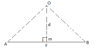
Length of a line will be equal to magnitude of force. In the figure, Force F is represented by line AB.
- Now let O is the moment center &
OM = d = perpendicular distance
By definition, Mo = F xd
Now join OA & OB, then
In Δ OAB
Area (ΔOAB) = ½ x AB x OM
2 (Area of ΔOAB) = F xd = Mo
Thus the moment of any force about any point is numerically equal to twice area of triangle in which base represents force & height represents the perpendicular distance.
Moment of a Force about a point:
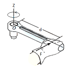
When a force is applied such that it creates rotation at the point of application along line of application, this tendency to rotate is called as torque, or the moment of a force. For example, consider a wrench used to unscrew the bolt in Fig. Below.
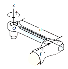
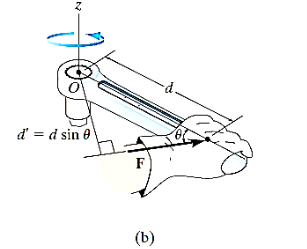
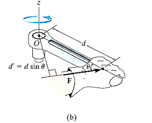
Note that if the force F is applied at an angle less than 900, Fig. (bas moment arm is smaller, it will be more difficult to turn.
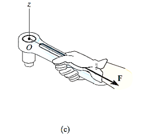
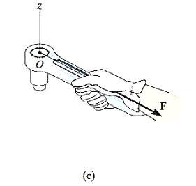
If F is applied along the length of wrench, Fig. (c), the moment arm will be zero. Hence moment will also be zero.
Thus, using the above observations, we can generalize accordingly.
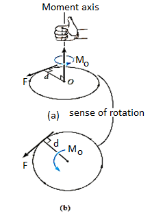
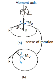
The magnitude of the moment is given by,

Where d is the moment arm or perpendicular distance from the axis at point O to the line of action of the force. Units are. N*m or lb*ft.
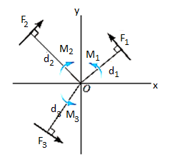
Resultant Moment: For two-dimensional problems, where all the forces lie within the x–y plane, Fig. Below, the resultant moment about point O (the z axis) can be determined by finding the algebraic sum of the moments caused by all the forces in the system. As a convention, we will generally consider positive moments as counterclockwise since they are directed along the positive z axis (out of the page). Clockwise moments will be considered to be negative. Doing this, the directional sense of each moment can be represented by a plus or minus sign. Thus, fig. Below shows the sign conventions.
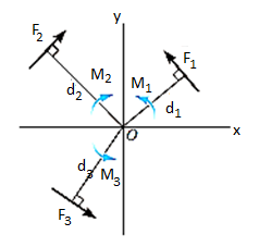

As we know that product of Scalar and vector quantity is always a vector quantity. Hence, the Moment of a force or torque is a vector quantity, and can be calculated using cross-product.
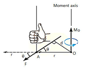
The moment of a force F about point O, or actually about the moment axis passing through O and perpendicular to the plane containing O and F, Fig. Below, can be expressed using the vector cross product, namely,
MO = r X F
Here r represents a position vector directed from O to any point on the line of action of F. We will now show that indeed the moment when determined by this cross product, has the proper magnitude and direction.
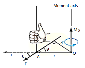
The magnitude of the cross product is defined as MO = rFsin where the angle
  is measured between the tails of r and F. To establish this angle, r must be treated as a sliding vector so that
  can be constructed properly. Since the moment arm d = rsin
 therefore,
MO = rFsin
MO = Fd
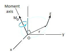
Cartesian Vector Formulation: If we establish x, y, z coordinate axes, then the position vector r and force F can be expressed as Cartesian vectors, Fig. (a) below.
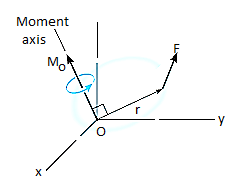
Formulating the equation in matrix format we have,

Where,
rx, ry, rz represent the x, y, z components of the position vector drawn from point O to any point on the line of action of the force.
Fx, Fy, Fz represent the x, y, z components of the force vector.
If the determinant is expanded, we will get the value of MO as,
MO = (ryFz – rzFy) i – (rxFz – rzFx) j + (rxFy – ryFx) k
Moment of a Force about a Specified Axis:
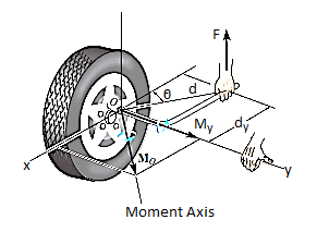
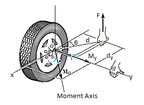
Sometimes, the moment produced by a force about a specified axis must be determined. For example, suppose the lug nut at O on the car tire in Fig. Above needs to be loosened. The force applied to the wrench will create a tendency for the wrench and the nut to rotate about the moment axis passing through O; however, the nut can only rotate about the y axis. Therefore, to determine the turning effect, only the y component of the moment is needed, and the total moment produced is not important. To determine this component, we can use either a scalar or vector analysis.
Scalar Analysis. To use a scalar analysis in the case of the lug nut in Fig. Above, the moment arm perpendicular distance from the axis to the line of action of the force is dy = d cos  . Thus, the moment will be
MOy = F (d cos )
)
Vector Analysis: To find the moment of force F in above figure about the y axis using a vector analysis, we must first determine the moment of the force about any point O on the y axis by applying MO = r x F. The component My along the y axis is the projection of MO onto the y axis. It can be found using the dot product discussed above, so that My = j*MO = j*(r x F) where j is the unit vector for the y axis.
We can generalize this approach by letting ua be the unit vector that specifies the direction of the axis shown in Fig. 4–21. Then the moment of F about the axis is

This combination is referred to as the scalar triple product. If the vectors are written in Cartesian form, we have


Equivalent Moment:
The equivalent moment acting on a system of forces can be calculated as illustrated in the following examples:
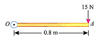
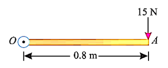
e.g., 5: A force of 15 N is applied perpendicular to the edge of a door 0.8 m wide as shown in Fig. Below. Find the moment of the force about the hinge.
Solution:
Given: Force applied (P) = 15 N and width of the door (l) = 0.8 m
Moment when the force acts perpendicular to the door as shown in fig.
We know that the moment of the force about the hinge is given as,
MO = P × l = 15 × 0.8 = 12.0 N-m
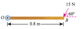
If the force is to be applied at a particular angle according to fig. Below,
Then the calculations are done in following procedure.
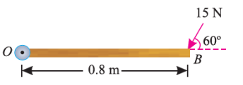
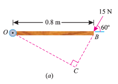
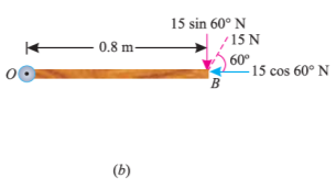
As the force applied in the question above is inclined at an angle of 600 with the horizontal, we can calculate the moment of force by two methods, either by finding out the perpendicular distance between the hinge and the line of action of the force as shown in Fig. (a) or by finding out the vertical component of the force as shown in Fig. (b) below.
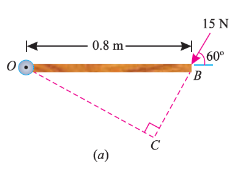
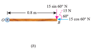
From the geometry of Fig. (a), we find that the perpendicular distance between the line of action of the force and hinge,
OC = OB sin 60° = 0.8 × 0.866 = 0.693 m
∴ Moment = 15 × 0.693 = 10.4 N-m
In the second case, we know that the vertical component of the force
= 15 sin 60° = 15 × 0.866 = 13.0 N
∴ Moment = 13 × 0.8 = 10.4 N-m
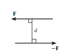
Couple can be defined as combination of two forces which are of equal magnitude but are opposite in direction, and are separated by a perpendicular distance d as shown in figure below. This can be illustrated by considering that when we are driving a car, to take a right turn, the right hand imparts a pull downwards on the steering wheel and the left hand imparts a push on steering wheel upwards, thus creating a couple. This moment created by couple is known as Couple Moment.
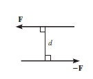
This, in scalar formulation, Formula for couple is given as,

Where F is magnitude of force and d is perpendicular distance between the forces. For finding the direction, the same method is used which is used for moment about a point, i.e. Right Hand rule.
If more than two moments are created, their resultant can be determined using vector addition. i.e., MR = M1 + M2.
Generalized equation for more than one couple moments is given as,

Properties of Couple:
1. Two unlike parallel, non-collinear forces of same magnitude will form couple.
2. Resultant of couple is always zero.
3. Moment of couple is product of one of the forces & lever arm of couple.
M = F xd
Lever arm of couple = ḻlar distance between couple forces.
4. Couple cannot be balanced by single force.
5. Couple can be balanced only by another couple of opposite nature.
6. Moment of couple is independent of moment centre. i.e. Ref. Point is not required to take moment of couple.

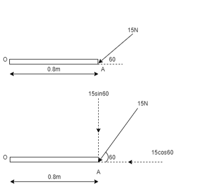
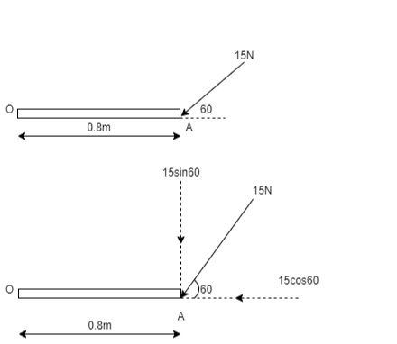
Q. A force of 15 N is applied at an angle of 600 to the edge of door as shown in figure. Find the moment of this force.
Solution:
Resolving force at point B & then taking the moment about point O,
M0 = (15 Cos 60 x 0) + (15 Sin 60 x 0.8)
= 0 + 10.39
M0 = 10.39 N.m
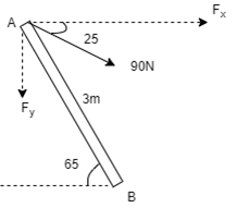
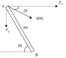
Q. A 90 N force is applied to the control rod AB. Determine moment of this Force about point B.
Solution:
As we don’t know perpendicular distance be tn force & point ‘ B ’, Let us resolve the force into two components.
X – Component of force
Fx = 90 Cos 25 = 81.567 N
Y – Component of force
Fy = 90 Sin 25 = 38.036
Now taking moments about point B.
MB = [Fx x (3 Sin 65)] - [Fy x (3 Cos 65)]
MB = (81.65 x 2.72) – (38.036 x 1.27)
= 221.843 – 48.31
MB = 173.53 N.m
Examples on Non concurrent forces & use of Varigon’s theorem
1. Determine the resultant of the system of forces acting on a beam as shown in figure.

Above Force system is Non concurrent force system.
Resolving the forces horizontally,
∑ Fx = - 20 Cos 60 = - 10 KN = 10 KN (toward left)
Resolving forces vertically,
∑Fy = - 20 – 30 – 20 Sin 60
= - 67.32 KN
∑Fy = 67.32 KN (downwards)
Resultant, R = √ (∑ Fx) 2 + (∑Fy) 2 = √10 2 + 67.322
R = 68.06 KN
Direction of Resultant,
Tanα = ∑Fy / ∑ Fx = 67.32 / 10.00
α = 81.550
Now taking moment about point A & using Varignon’s theorem.
∑MA = Moment of resultant A
(20 x 1.5) + (30 x 3) + (20 Sin 60 x 6) = (∑ Fx x 0 ) + (∑Fyx X)
223.92 = 67.32 x X
X = 223.92 / 67.32 = 3.326 m from point A
Ans

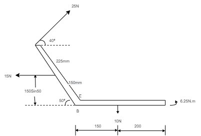
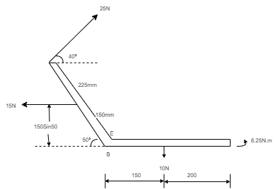
Q. For a given force system, find the resultant in magnitude & direction. Also find the location of Resultant.
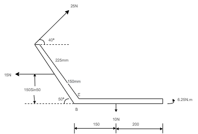
Solution
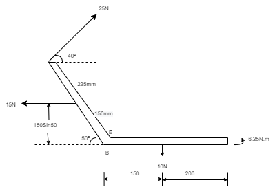
Resolving forces horizontally,
∑ Fx = - 15 + 25 Cos 40 = 4.15 N (toward right)
Resolving forces vertically,
∑Fy = 25 Sin 40 – 10
= 6.07 n (upward)
R = √(∑ Fx) 2 + (∑Fy)2
= √4.152 + 6.072
R = 7.35 N
Tanα = ∑Fy / ∑ Fx = 6.07 / 4.15
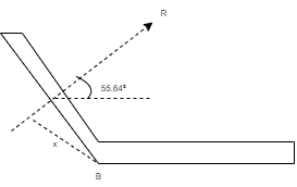
α= 55.640 - - - Angle made by resultant
To find exact position of R, let x is the perpendicular distance betn R & point B.
Using Varignon’s theorem at point B.
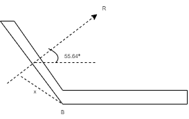
R x X = ∑MB
= (10 x 150) – (15 x 150 Sin 50) + ( 25 x 375 ) – ( 6.25 x 1000 )
= 1500 – 1723.6 + 9375 – 6250
= 2901.4 N.mm (clockwise)
x = 2901.4 / R
= 2901.4 / 7.35
x = 394.75 mm from point B.
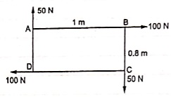
(Q) Find resultant moment of two couples for the loading as shown in Fig
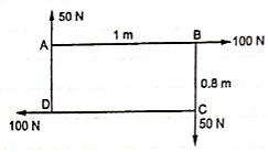
Moment of 50 N couple is clockwise,
= 50 x 1
= 50 N.m
Moment of 100 N couple is also clockwise
= 100 x 0.8 = 80 N.m.
Resultant Moment = 50 + 80 = 130 N.m
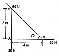
(Q) Find the resultant and its point of application on y – axis for the force system acting on Triangular plate as shown in fig.
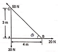
θ = tan-1 (3/4)
= 36.860 with Horizontal
Resolving forces in x & y dirn
∑ Fx = 20 – 50 Cosθ
= 20 – 50 Cos 36.86
= - 20 N
= 20 N
∑Fy = - 30 + 50 Sin 36.86
= 0.00007
≈ 0
R = √(∑ Fx) 2 + (∑Fy)2
= 20 N toward left (as ∑ Fy = 0 )
Let us apply Varignons theorem at point B
∑MB = R.x
( 30 x 4 ) = Rx
Rx = -120 N.m = 120 N.m
As moment of Resultant is negative i.e. it is anticlockwise
-Rx = -120
X = -120 / -20 = 6 m
X = 6 m from point B and it will be above point. B to create anticlockwise moment.
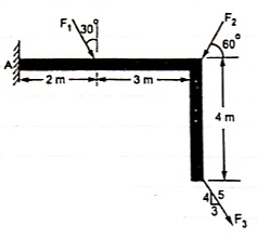
(Q) If the resultant moment about point A is 4800 Nm clockwise, determine the magnitude of F3 if F1 = 300 N and F2 = 400 N.
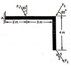
Given: Resultant Moment = 4800 N.m
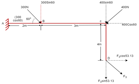
Let us apply Varignon’s theorem at point A,
∑MB = (R.x )
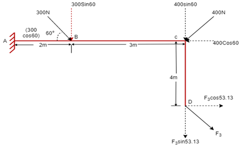
[(300 60) x 2] + [(400 Sin 60) x 5] + [(F3 Sin 53.13 x 5)] – [(F3 Cos 53.13) x 4] = 4800
519.62 + 1732.05 + 3.99 F3 – 2.4 F3 = 4800
2251.67 + 1.59F3 = 4800
F3 = 2548.33 / 1.59 F3 = 2548.33 / 1.6
OR
F3 = 1602.72 NF3 = 1592.7 N
(Q) The three forces shown in Fig. Create a vertical resultant acting through point B. If P = 361 N, compare the values of T and F.

From given figure,
1. Angle made by Force P is, = tan-1 (3/3) = 450 with Horizontal
2. Angle made by Force F is, = tan-1 (1/3) = 18.430 with Horizontal
3. Angle made by Force T is, = tan-1 (3/1) = 71.560 with Horizontal

Resolving forces along x & y dirn,
As Resultant is vertical, let it is upward, then
∑ Fx = 0& ∑Fy = R
∑ Fx = P Cos 45 + F Cos 18.43 – T Cos 71.56
0 = 361 Cos 45 + F Cos 18.43 – T Cos 71.56
0 = 255.26 + 0.95 F – 0.32 T
0.95 F – 0.32 T = - 255.26 . . . . (1)
∑Fy = P Sin 45 – F Sin 18.43 + T Sin 71.56
R = 361 Sin 45 – F Sin 18.43 + T Sin 71.56
R = 255.26 – 0.32 F + 0.95 T …… (2)
Now as it is given that Resultant acts at point B, let us apply Varignon’s theorem at point B.
∑MB = R.x
But as R is acting at B point, its perpendicular distance from point B itself will be zero.
∑MB = R.x
(P Cos 45 x 1) – (P Sin 45 x 2) + (T Cos 71.56 x 1) – (T Sin 71.56 x 1) – (F Cos 18.43 x 1) + (F Sin 18.43 x 2) = R x 0
As P = 361 N
-255.26 – (255.26 x 2) + 0.32 T – 0.95 T – 0.95 F + (0.32 F x 2) = 0
-765.78 + 0.32 T – 0.95 T – 0.95 F + 0.64 F = 0
-765.78 – 0.63 T – 0.31 F = 0
– 0.31 F – 0.63 T = 765.78 . . . . (3)
Solving equation (1) and (3) simultaneously

F = -581.716 N &
T = -929.282 N
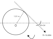
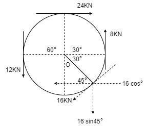
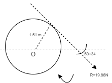
(Q) Determine the resultant of four forces tangent to the circle of radius 1.5 m as shown. Determine its location w.r.t. ‘O’.
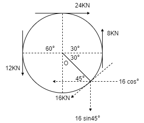
Resolving forces in X and Y direction,
∑ Fx = 24 - 16 Cos 45
= 12.69 KN ( )
∑Fy = -12 + 8 – 16 Sin 45
= -15.31 kN
= 15.31 kN ( )
Resultant R = √(∑ Fx) 2 + (∑Fy)2
= √ 12.69 2 + (-15.31)2
R = 19.88 kN
Direction of Resultant,
α = tan-1(∑Fy / ∑ Fx)
α = tan-1(15.31 / 12.69)
α = 50.350in 4th quadrant
To know exact location of Resultant, let us apply Varignon’s theorem at point O.
∑MO = R.x
-(12 x 1.5) + (24 x 1.5) – (8 x 1.5) + (16 x 1.5) = (19.88 x X)
30 = R.x
As product of R.x is positive it means moment of Resultant is positive. To create positive clockwise moment of Resultant it must be acting on Right side of O (in 4th quadrant).
30 = 19.88 x X
X = 1.51 m from O on the right hand side.
Force is basically a vector quantity which may be either push or pull exerted during interaction of one object with other. Force is sort of interaction, when the interaction stops between objects, force is considered to be absent.
Types of Forces:
They can be divided as Contact Forces and Action at a distance type forces.
- Contact Forces:
These forces act when there exists contact between surfaces or objects and are subdivided as:
Frictional Force: This type of force exists between the two surfaces making contact and having irregularities or roughness between the mating surfaces. E.g., Frictional force between the tyre of car and road causing it to wear and tear.
Tension Force: This type of force gets transmitted through ropes, wires or cables when some object is suspended or held using them. E.g., A block of material freely suspended using some rope and pulley arrangement.
Normal Force: This type of force exists when a particular object is placed on some other object, thus the weight of one object acts as a kind of force onto the other stable object. E.g., Book placed on the table.
Air resistance Force: This kind of force comes into action when motion of one object in presence of air, such that the air particle opposes the motion of that object, creating a kind of resistance force acting onto the body. E.g., An object falling from sky gets heated due to air resistance on the object.
Applied Force: This type of force is acted on an object externally, either to create a motion or retard the ongoing motion. E.g., Force applied by brakes to stop a moving vehicle.
Spring Force: This type of force exists when the spring which is compressed or stretched and gives a reaction force causing compression or stretching.
b. Action-at-a-Distance type Forces
These types of forces do not need to have physical contact between the two surfaces to exist. Some of these types of forces are
Gravitational Force: This force is considered to exist between any two bodies and is governed using Law of Gravitational Force given by Newton.
Electrical Force: This type of force is considered to be existing between two charged particles placed near each other causing pull or push between them.
Magnetic Force: This type of force is present between magnetic poles which may cause either pull or push of the magnets.
Effects of a force:
It may produce the effects on body on which it is acted as:
1. Motion of the body may be changed.
2. It may retard the motion of a body.
3. It may reduce the acting forces to make it stop or be in equilibrium
4. It may even create internal stresses in the body.
Characteristics of a force:
Following are the characteristics of a force:
1. Magnitude of the force (i.e., 100 N, 50 N, 20 kN, 5 kN, etc.)
2. The direction of the line, along which the force acts.
3. Nature of the force. This is denoted by placing an arrow head on the line of action of the force.
4. The point at which (or through which) the force acts on the body.
Particle Equilibrium in 2-D and 3-D:
A particle is said to be in equilibrium if it remains in rest condition or in a particular constant velocity if it is already in motion. If we consider in Static Equilibrium, then essentially a particle is considered to be in rest condition. Thus, for a particle to be in rest condition, it needs to satisfy the Newton’s First Law of motion that states that a particle remains in state of rest or motion, until an external unbalanced force act on it. Thus, the generalized equation for a particle to be in equilibrium states that resultant force acting on any particle should be zero for the particle to be in equilibrium,
i.e.,  .
.
Some generalized steps for solving particle equilibrium problem in 2D and 3D systems are
Drawing a free-body diagram which is discussed in next section.
Using equations of equilibrium for solving the unknowns and desired quantities.
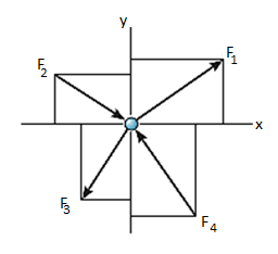
Thus, the equations of equilibrium for two-dimensional coplanar force system are given by considering that the particle is present in x-y plane as shown in fig. Below, then the force can be resolved into i and j components.
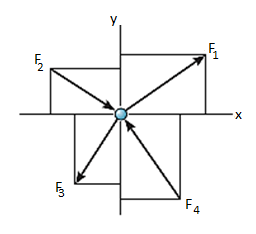
For equilibrium, the forces must add on to produce a zero-force output, i.e.,
Σ F = 0
Σ Fx i + Σ Fy j = 0
Thus, for satisfying this vector equation, the x and y component must be zero as mentioned in earlier points. Hence,
Σ Fx = 0
Σ Fy = 0
Thus, for solving two-dimensional coplanar force problems using conditions of equilibrium, we can follow the below-mentioned procedure.
Free-Body Diagram.
- In any orientation, establish x and y axes.
- Then mark all the known and unknown forces in figure.
- Unknown forces are also assumed and plotted.
Equilibrium equation.
- Apply the equations of equilibrium, Σ Fx = 0 and Σ Fy = 0.
- The forces are directed as positive for those along positive axis and vice-versa.
- If the resultant comes out to be negative value, it means that the direction needs to be reversed for that is already considered.
As we know, the sufficient case for stating equilibrium for a body under combination of forces is Σ F = 0.
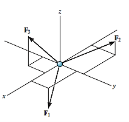
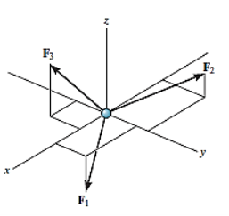
For any three-dimensional force system, as shown in Fig. Below, we can resolve the forces into their respective i, j, k components, so that
Σ Fx i + Σ Fy j + Σ Fz k = 0
To satisfy this equation we require,
Σ Fx = 0
Σ Fy = 0
Σ Fz = 0
These three equations state that the algebraic sum of the components of all the forces acting on the particle along each of the coordinate axes must be zero. Using these equations mentioned we can solve for maximum three of the unknowns, shown by coordinate direction angles or magnitudes of forces shown on the particle’s free-body diagram.
For solving three-dimensional problem, we can use the following procedure.
Free Body Diagram:
- In any orientation, establish x and y axes.
- Then mark all the known and unknown forces in figure.
- Unknown forces are also assumed and plotted.
Equations of Equilibrium.
- Apply the equations of equilibrium, Σ Fx = 0, Σ Fy = 0 and Σ Fz = 0.
- Initially we can display as a Cartesian vector if it becomes to solve the problem regularly, substitute these vectors into Σ F = 0 and then set the i, j, k components equal to zero.
- If the resultant comes out to be negative value, it means that the direction needs to be reversed for that is already considered.
Problems in two and three dimensions:
The above-mentioned procedure (2.2) is used for finding solutions to two- and three-dimensional problems. This procedure can be better understood through some of the examples mentioned below.
Problems in Two-dimensions:
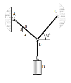
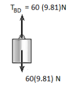
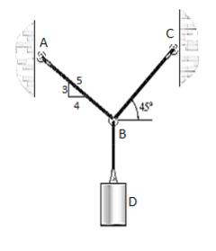
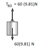
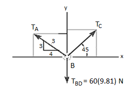
e.g., 1: Determine the tension that will be there in cables BA and BC necessary to support the 60-kg cylinder in Fig. Below.
Solution:
The first step involves drawing the free-body diagram of the given example. As this is two-dimensional structure, we will follow the method mentioned for two-dimensional coplanar structure.
1. Free-Body Diagram. Due to equilibrium, the weight of the cylinder sources the tension in cable TBD = 60*(9.81), Fig. (b). Using the equilibrium at B, forces in BA and BC can be found out. The free-body diagram is shown in Fig. Below (c). The magnitudes of TA and TC are unknown, but their directions are known.
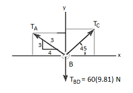
2. Equations of Equilibrium: Applying the equations of equilibrium along the x and y axes, we have
Σ Fx = 0 i.e., TC cos 45° - (4/5) TA = 0
Σ Fy = 0 i.e., TC sin 45° + (3/5) TA - 60(9.81) N = 0
Solving the above equations, we get, TC = 475.66 N = 476 N
Then, substituting this value in above equation,
TA = 420 N
In this way, using the equilibrium equations, we can solve for the unknown force in the given problem.
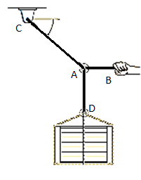
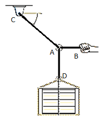
e.g., 2: The 200-kg crate in Fig. Below is suspended using the ropes AB and AC. Each rope can withstand a maximum force of 10 kN before it breaks. If AB always remains horizontal, determine the smallest angle to which the crate can be suspended before one of the ropes breaks.
Solution:
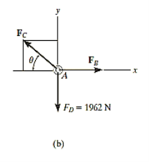
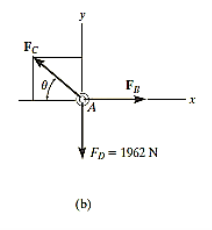
Free-Body Diagram: We will initially understand the equilibrium of ring. There are three forces acting on it, as shown in fig. (b). The magnitude of is equal to the weight of the crate, i.e.,
FD = 200 (9.81) N = 1962 N < 10 kN
Equations of Equilibrium: Applying the equations of equilibrium along the x and y axes,
Σ Fx = 0
i.e. - FC cos θ + FB = 0
Therefore FC = (FB / cos θ)
Σ Fy = 0
i.e., FC sin θ - 1962 N = 0
As seen from the above equations, FC is always greater than FB as cos θ is less than or equal to 1. So, rope AC will reach the max value of tensile force of 10 kN before that of rope AB. Thus, substituting FC = 10 kN in the above equations, we get
[10(103) N] sin θ - 1962 N = 0
Thus, θ = 11.30
The force developed in rope AB can be obtained by substituting the values for θ and FC into Equations mentioned above.
We get, FB = 9.81 kN.
In this way, using equations of equilibrium and free-body diagrams, we can calculate unknown quantities of the given problem.
Problems in Three-dimensions:
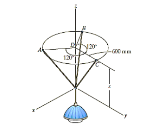
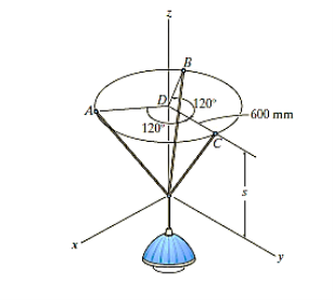
e.g., 3: The 10-kg lamp in Fig. Below is suspended from the three equal-length cords. Find the smallest vertical distance s from the ceiling if force built in cord is not to go beyond 50 kN.
Solution:
For solving these three-dimensional numerical, we will follow the same procedure mentioned above.
Free-Body Diagram: Because of symmetry, the distance are as  mm. It follows that from Σ Fx = 0 and Σ Fy = 0, the tension T in each cord will be the same. Also, the angle between z axis and every cord is
  .
.
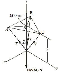
Equation of Equilibrium: Applying the equilibrium equation along the z-axis, with T = 50 N, we have
Σ Fz = 0;
3[(50 N) cos  ] - 10(9.81) N = 0
 = cos-1 (98.1 / 150)
= 49.160
Now,
By geometry shown in free-body diagram,
Tan 49.160 = (600 / s)
s = 519 mm
In this way, three-dimensional problems are solved using equations of equilibrium.
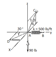
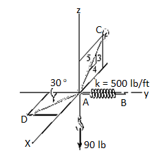
e.g., 4: A 90-lb load is being suspended from a hook as shown in Fig. Below. If the load is being supported by two cables and a spring having a stiffness of k = 500 lb/ft, find the force in the cables and the stretch of the spring for equilibrium. Cable AD lies in the x–y plane and cable AC lies in the x–z plane.
Solution:
Initially, force in spring is determined to determine stretching of spring.
Free-Body Diagram. A point is chosen for all analysis as all the points are concurrent here. The free-body diagram for the problem is shown in Fig. Below.
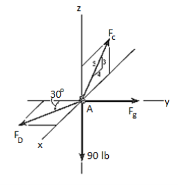
Equations of Equilibrium. We can resolve each force in x, y and z components, and so we can use three scalar equations of equilibrium. Considering components directed along each positive axis as “positive,” we have
Σ Fx = 0
FD sin 30° - (4/5) FC = 0
Σ Fy = 0
-FD cos 30° + FB = 0
Σ Fz = 0
(3/5) FC – 90 lb = 0
Thus, solving the above-mentioned equations, we get,
FC = 150 lb
FD = 240 lb
FB = 207.8 lb
The stretch of the spring is therefore
FB = ksAB
207.8 lb = (500 lb/ft) (sAB)
sAB = 0.416 ft
Thus, the method discussed earlier can be followed as shown in the examples for finding out the unknown quantities in two- and three-dimensional problems using equations of equilibrium.
References:
1. Engineering Mechanics: F. L. Singer
2. Engineering Mechanics: Timoshenko & Young
3. Engineering Mechanics: Bear & Johnston
4. Engineering Mechanics: I. H. Shames
5. Engineering Mechanics: A. Nelson
Unit - 1
Important Vector Quantities
As the name suggests, it is a vector, which signifies the position of a body (or a point) with respect to the origin (or with respect to a certain point).
Vector r is the position vector of the point P with respect to the origin O and a, b, c are the angles with the x, y and z axis
So, r = r cos a i + r cos b j + r cos c kis the position vector of point P
A convenient way to specify the position of an object is with the help of a coordinate system. We choose a fixed point, called the origin and three directed lines, which pass through the origin and are perpendicular to each other. These lines are called the coordinate axes of a three-dimensional rectangular (Cartesian) coordinate system and are labelled the x-, y-, and z-axis. Three numbers with units specify the position of a point P. These numbers are the x-, y-, and z-coordinates of the point P. The coordinates of the point P in the diagram to the right are (a, b, c).
The coordinates of the point P are the components of the position vector. A unit vector pointing in the x-direction has a x-component of 1 and y- and z- components of zero. It is denoted by i. Similarly, a unit vector pointing in the y-direction is denoted by j, and a unit vector pointing in the z-direction is denoted by k. Unit vectors are direction indicators.
The components of any vector add up to form the vector itself.
The position vector of a point P with coordinates (a, b, c) may be written in terms of its components as
r = ai + bj + ck.
The magnitude of the position vector is its length r. It depends on the choice of the origin of the coordinate system. It is the straight-line distance of P from the origin. Below is a 3D representation of a position vector r = ai + bj +ck
The turning effect produced by a force on the body on which it acts is called as Moment.
Moment of force about any point is the product of magnitude of force and perpendicular distance of force from the point about which moment is to be taken.
Let force F is applied at point A as shown & O is any point about which we want to take moment.
Thus from point O, draw OM line perpendicular to the line of action of force.
OM = d = Perpendicular distance between Force & point O.
Moment = M = F x d
Graphical representation of Moment:
- Select suitable scale to locate the force graphically.
- Draw a line parallel to line of action of force. Length of this line can be calculated from selected scale.
 -
-
Length of a line will be equal to magnitude of force. In the figure, Force F is represented by line AB.
- Now let O is the moment center &
OM = d = perpendicular distance
By definition, Mo = F xd
Now join OA & OB, then
In Δ OAB
Area (ΔOAB) = ½ x AB x OM
2 (Area of ΔOAB) = F xd = Mo
Thus the moment of any force about any point is numerically equal to twice area of triangle in which base represents force & height represents the perpendicular distance.
Moment of a Force about a point:
When a force is applied such that it creates rotation at the point of application along line of application, this tendency to rotate is called as torque, or the moment of a force. For example, consider a wrench used to unscrew the bolt in Fig. Below.
Note that if the force F is applied at an angle less than 900, Fig. (bas moment arm is smaller, it will be more difficult to turn.
If F is applied along the length of wrench, Fig. (c), the moment arm will be zero. Hence moment will also be zero.
Thus, using the above observations, we can generalize accordingly.
The magnitude of the moment is given by,

Where d is the moment arm or perpendicular distance from the axis at point O to the line of action of the force. Units are. N*m or lb*ft.
Resultant Moment: For two-dimensional problems, where all the forces lie within the x–y plane, Fig. Below, the resultant moment about point O (the z axis) can be determined by finding the algebraic sum of the moments caused by all the forces in the system. As a convention, we will generally consider positive moments as counterclockwise since they are directed along the positive z axis (out of the page). Clockwise moments will be considered to be negative. Doing this, the directional sense of each moment can be represented by a plus or minus sign. Thus, fig. Below shows the sign conventions.

As we know that product of Scalar and vector quantity is always a vector quantity. Hence, the Moment of a force or torque is a vector quantity, and can be calculated using cross-product.
The moment of a force F about point O, or actually about the moment axis passing through O and perpendicular to the plane containing O and F, Fig. Below, can be expressed using the vector cross product, namely,
MO = r X F
Here r represents a position vector directed from O to any point on the line of action of F. We will now show that indeed the moment when determined by this cross product, has the proper magnitude and direction.
The magnitude of the cross product is defined as MO = rFsin where the angle
  is measured between the tails of r and F. To establish this angle, r must be treated as a sliding vector so that
  can be constructed properly. Since the moment arm d = rsin
 therefore,
MO = rFsin
MO = Fd
Cartesian Vector Formulation: If we establish x, y, z coordinate axes, then the position vector r and force F can be expressed as Cartesian vectors, Fig. (a) below.
Formulating the equation in matrix format we have,

Where,
rx, ry, rz represent the x, y, z components of the position vector drawn from point O to any point on the line of action of the force.
Fx, Fy, Fz represent the x, y, z components of the force vector.
If the determinant is expanded, we will get the value of MO as,
MO = (ryFz – rzFy) i – (rxFz – rzFx) j + (rxFy – ryFx) k
Moment of a Force about a Specified Axis:
Sometimes, the moment produced by a force about a specified axis must be determined. For example, suppose the lug nut at O on the car tire in Fig. Above needs to be loosened. The force applied to the wrench will create a tendency for the wrench and the nut to rotate about the moment axis passing through O; however, the nut can only rotate about the y axis. Therefore, to determine the turning effect, only the y component of the moment is needed, and the total moment produced is not important. To determine this component, we can use either a scalar or vector analysis.
Scalar Analysis. To use a scalar analysis in the case of the lug nut in Fig. Above, the moment arm perpendicular distance from the axis to the line of action of the force is dy = d cos  . Thus, the moment will be
MOy = F (d cos )
)
Vector Analysis: To find the moment of force F in above figure about the y axis using a vector analysis, we must first determine the moment of the force about any point O on the y axis by applying MO = r x F. The component My along the y axis is the projection of MO onto the y axis. It can be found using the dot product discussed above, so that My = j*MO = j*(r x F) where j is the unit vector for the y axis.
We can generalize this approach by letting ua be the unit vector that specifies the direction of the axis shown in Fig. 4–21. Then the moment of F about the axis is

This combination is referred to as the scalar triple product. If the vectors are written in Cartesian form, we have


Equivalent Moment:
The equivalent moment acting on a system of forces can be calculated as illustrated in the following examples:
e.g., 5: A force of 15 N is applied perpendicular to the edge of a door 0.8 m wide as shown in Fig. Below. Find the moment of the force about the hinge.
Solution:
Given: Force applied (P) = 15 N and width of the door (l) = 0.8 m
Moment when the force acts perpendicular to the door as shown in fig.
We know that the moment of the force about the hinge is given as,
MO = P × l = 15 × 0.8 = 12.0 N-m
If the force is to be applied at a particular angle according to fig. Below,
Then the calculations are done in following procedure.
As the force applied in the question above is inclined at an angle of 600 with the horizontal, we can calculate the moment of force by two methods, either by finding out the perpendicular distance between the hinge and the line of action of the force as shown in Fig. (a) or by finding out the vertical component of the force as shown in Fig. (b) below.
From the geometry of Fig. (a), we find that the perpendicular distance between the line of action of the force and hinge,
OC = OB sin 60° = 0.8 × 0.866 = 0.693 m
∴ Moment = 15 × 0.693 = 10.4 N-m
In the second case, we know that the vertical component of the force
= 15 sin 60° = 15 × 0.866 = 13.0 N
∴ Moment = 13 × 0.8 = 10.4 N-m
Couple can be defined as combination of two forces which are of equal magnitude but are opposite in direction, and are separated by a perpendicular distance d as shown in figure below. This can be illustrated by considering that when we are driving a car, to take a right turn, the right hand imparts a pull downwards on the steering wheel and the left hand imparts a push on steering wheel upwards, thus creating a couple. This moment created by couple is known as Couple Moment.
This, in scalar formulation, Formula for couple is given as,

Where F is magnitude of force and d is perpendicular distance between the forces. For finding the direction, the same method is used which is used for moment about a point, i.e. Right Hand rule.
If more than two moments are created, their resultant can be determined using vector addition. i.e., MR = M1 + M2.
Generalized equation for more than one couple moments is given as,

Properties of Couple:
1. Two unlike parallel, non-collinear forces of same magnitude will form couple.
2. Resultant of couple is always zero.
3. Moment of couple is product of one of the forces & lever arm of couple.
M = F xd
Lever arm of couple = ḻlar distance between couple forces.
4. Couple cannot be balanced by single force.
5. Couple can be balanced only by another couple of opposite nature.
6. Moment of couple is independent of moment centre. i.e. Ref. Point is not required to take moment of couple.

Q. A force of 15 N is applied at an angle of 600 to the edge of door as shown in figure. Find the moment of this force.
Solution:
Resolving force at point B & then taking the moment about point O,
M0 = (15 Cos 60 x 0) + (15 Sin 60 x 0.8)
= 0 + 10.39
M0 = 10.39 N.m
Q. A 90 N force is applied to the control rod AB. Determine moment of this Force about point B.
Solution:
As we don’t know perpendicular distance be tn force & point ‘ B ’, Let us resolve the force into two components.
X – Component of force
Fx = 90 Cos 25 = 81.567 N
Y – Component of force
Fy = 90 Sin 25 = 38.036
Now taking moments about point B.
MB = [Fx x (3 Sin 65)] - [Fy x (3 Cos 65)]
MB = (81.65 x 2.72) – (38.036 x 1.27)
= 221.843 – 48.31
MB = 173.53 N.m
Examples on Non concurrent forces & use of Varigon’s theorem
1. Determine the resultant of the system of forces acting on a beam as shown in figure.

Above Force system is Non concurrent force system.
Resolving the forces horizontally,
∑ Fx = - 20 Cos 60 = - 10 KN = 10 KN (toward left)
Resolving forces vertically,
∑Fy = - 20 – 30 – 20 Sin 60
= - 67.32 KN
∑Fy = 67.32 KN (downwards)
Resultant, R = √ (∑ Fx) 2 + (∑Fy) 2 = √10 2 + 67.322
R = 68.06 KN
Direction of Resultant,
Tanα = ∑Fy / ∑ Fx = 67.32 / 10.00
α = 81.550
Now taking moment about point A & using Varignon’s theorem.
∑MA = Moment of resultant A
(20 x 1.5) + (30 x 3) + (20 Sin 60 x 6) = (∑ Fx x 0 ) + (∑Fyx X)
223.92 = 67.32 x X
X = 223.92 / 67.32 = 3.326 m from point A
Ans

Q. For a given force system, find the resultant in magnitude & direction. Also find the location of Resultant.
Solution
Resolving forces horizontally,
∑ Fx = - 15 + 25 Cos 40 = 4.15 N (toward right)
Resolving forces vertically,
∑Fy = 25 Sin 40 – 10
= 6.07 n (upward)
R = √(∑ Fx) 2 + (∑Fy)2
= √4.152 + 6.072
R = 7.35 N
Tanα = ∑Fy / ∑ Fx = 6.07 / 4.15
α= 55.640 - - - Angle made by resultant
To find exact position of R, let x is the perpendicular distance betn R & point B.
Using Varignon’s theorem at point B.
R x X = ∑MB
= (10 x 150) – (15 x 150 Sin 50) + ( 25 x 375 ) – ( 6.25 x 1000 )
= 1500 – 1723.6 + 9375 – 6250
= 2901.4 N.mm (clockwise)
x = 2901.4 / R
= 2901.4 / 7.35
x = 394.75 mm from point B.
(Q) Find resultant moment of two couples for the loading as shown in Fig
Moment of 50 N couple is clockwise,
= 50 x 1
= 50 N.m
Moment of 100 N couple is also clockwise
= 100 x 0.8 = 80 N.m.
Resultant Moment = 50 + 80 = 130 N.m
(Q) Find the resultant and its point of application on y – axis for the force system acting on Triangular plate as shown in fig.
θ = tan-1 (3/4)
= 36.860 with Horizontal
Resolving forces in x & y dirn
∑ Fx = 20 – 50 Cosθ
= 20 – 50 Cos 36.86
= - 20 N
= 20 N
∑Fy = - 30 + 50 Sin 36.86
= 0.00007
≈ 0
R = √(∑ Fx) 2 + (∑Fy)2
= 20 N toward left (as ∑ Fy = 0 )
Let us apply Varignons theorem at point B
∑MB = R.x
( 30 x 4 ) = Rx
Rx = -120 N.m = 120 N.m
As moment of Resultant is negative i.e. it is anticlockwise
-Rx = -120
X = -120 / -20 = 6 m
X = 6 m from point B and it will be above point. B to create anticlockwise moment.
(Q) If the resultant moment about point A is 4800 Nm clockwise, determine the magnitude of F3 if F1 = 300 N and F2 = 400 N.
Given: Resultant Moment = 4800 N.m
Let us apply Varignon’s theorem at point A,
∑MB = (R.x )
[(300 60) x 2] + [(400 Sin 60) x 5] + [(F3 Sin 53.13 x 5)] – [(F3 Cos 53.13) x 4] = 4800
519.62 + 1732.05 + 3.99 F3 – 2.4 F3 = 4800
2251.67 + 1.59F3 = 4800
F3 = 2548.33 / 1.59 F3 = 2548.33 / 1.6
OR
F3 = 1602.72 NF3 = 1592.7 N
(Q) The three forces shown in Fig. Create a vertical resultant acting through point B. If P = 361 N, compare the values of T and F.

From given figure,
1. Angle made by Force P is, = tan-1 (3/3) = 450 with Horizontal
2. Angle made by Force F is, = tan-1 (1/3) = 18.430 with Horizontal
3. Angle made by Force T is, = tan-1 (3/1) = 71.560 with Horizontal

Resolving forces along x & y dirn,
As Resultant is vertical, let it is upward, then
∑ Fx = 0& ∑Fy = R
∑ Fx = P Cos 45 + F Cos 18.43 – T Cos 71.56
0 = 361 Cos 45 + F Cos 18.43 – T Cos 71.56
0 = 255.26 + 0.95 F – 0.32 T
0.95 F – 0.32 T = - 255.26 . . . . (1)
∑Fy = P Sin 45 – F Sin 18.43 + T Sin 71.56
R = 361 Sin 45 – F Sin 18.43 + T Sin 71.56
R = 255.26 – 0.32 F + 0.95 T …… (2)
Now as it is given that Resultant acts at point B, let us apply Varignon’s theorem at point B.
∑MB = R.x
But as R is acting at B point, its perpendicular distance from point B itself will be zero.
∑MB = R.x
(P Cos 45 x 1) – (P Sin 45 x 2) + (T Cos 71.56 x 1) – (T Sin 71.56 x 1) – (F Cos 18.43 x 1) + (F Sin 18.43 x 2) = R x 0
As P = 361 N
-255.26 – (255.26 x 2) + 0.32 T – 0.95 T – 0.95 F + (0.32 F x 2) = 0
-765.78 + 0.32 T – 0.95 T – 0.95 F + 0.64 F = 0
-765.78 – 0.63 T – 0.31 F = 0
– 0.31 F – 0.63 T = 765.78 . . . . (3)
Solving equation (1) and (3) simultaneously

F = -581.716 N &
T = -929.282 N
(Q) Determine the resultant of four forces tangent to the circle of radius 1.5 m as shown. Determine its location w.r.t. ‘O’.
Resolving forces in X and Y direction,
∑ Fx = 24 - 16 Cos 45
= 12.69 KN ( )
∑Fy = -12 + 8 – 16 Sin 45
= -15.31 kN
= 15.31 kN ( )
Resultant R = √(∑ Fx) 2 + (∑Fy)2
= √ 12.69 2 + (-15.31)2
R = 19.88 kN
Direction of Resultant,
α = tan-1(∑Fy / ∑ Fx)
α = tan-1(15.31 / 12.69)
α = 50.350in 4th quadrant
To know exact location of Resultant, let us apply Varignon’s theorem at point O.
∑MO = R.x
-(12 x 1.5) + (24 x 1.5) – (8 x 1.5) + (16 x 1.5) = (19.88 x X)
30 = R.x
As product of R.x is positive it means moment of Resultant is positive. To create positive clockwise moment of Resultant it must be acting on Right side of O (in 4th quadrant).
30 = 19.88 x X
X = 1.51 m from O on the right hand side.
Force is basically a vector quantity which may be either push or pull exerted during interaction of one object with other. Force is sort of interaction, when the interaction stops between objects, force is considered to be absent.
Types of Forces:
They can be divided as Contact Forces and Action at a distance type forces.
- Contact Forces:
These forces act when there exists contact between surfaces or objects and are subdivided as:
Frictional Force: This type of force exists between the two surfaces making contact and having irregularities or roughness between the mating surfaces. E.g., Frictional force between the tyre of car and road causing it to wear and tear.
Tension Force: This type of force gets transmitted through ropes, wires or cables when some object is suspended or held using them. E.g., A block of material freely suspended using some rope and pulley arrangement.
Normal Force: This type of force exists when a particular object is placed on some other object, thus the weight of one object acts as a kind of force onto the other stable object. E.g., Book placed on the table.
Air resistance Force: This kind of force comes into action when motion of one object in presence of air, such that the air particle opposes the motion of that object, creating a kind of resistance force acting onto the body. E.g., An object falling from sky gets heated due to air resistance on the object.
Applied Force: This type of force is acted on an object externally, either to create a motion or retard the ongoing motion. E.g., Force applied by brakes to stop a moving vehicle.
Spring Force: This type of force exists when the spring which is compressed or stretched and gives a reaction force causing compression or stretching.
b. Action-at-a-Distance type Forces
These types of forces do not need to have physical contact between the two surfaces to exist. Some of these types of forces are
Gravitational Force: This force is considered to exist between any two bodies and is governed using Law of Gravitational Force given by Newton.
Electrical Force: This type of force is considered to be existing between two charged particles placed near each other causing pull or push between them.
Magnetic Force: This type of force is present between magnetic poles which may cause either pull or push of the magnets.
Effects of a force:
It may produce the effects on body on which it is acted as:
1. Motion of the body may be changed.
2. It may retard the motion of a body.
3. It may reduce the acting forces to make it stop or be in equilibrium
4. It may even create internal stresses in the body.
Characteristics of a force:
Following are the characteristics of a force:
1. Magnitude of the force (i.e., 100 N, 50 N, 20 kN, 5 kN, etc.)
2. The direction of the line, along which the force acts.
3. Nature of the force. This is denoted by placing an arrow head on the line of action of the force.
4. The point at which (or through which) the force acts on the body.
Particle Equilibrium in 2-D and 3-D:
A particle is said to be in equilibrium if it remains in rest condition or in a particular constant velocity if it is already in motion. If we consider in Static Equilibrium, then essentially a particle is considered to be in rest condition. Thus, for a particle to be in rest condition, it needs to satisfy the Newton’s First Law of motion that states that a particle remains in state of rest or motion, until an external unbalanced force act on it. Thus, the generalized equation for a particle to be in equilibrium states that resultant force acting on any particle should be zero for the particle to be in equilibrium,
i.e.,  .
.
Some generalized steps for solving particle equilibrium problem in 2D and 3D systems are
Drawing a free-body diagram which is discussed in next section.
Using equations of equilibrium for solving the unknowns and desired quantities.
Thus, the equations of equilibrium for two-dimensional coplanar force system are given by considering that the particle is present in x-y plane as shown in fig. Below, then the force can be resolved into i and j components.
For equilibrium, the forces must add on to produce a zero-force output, i.e.,
Σ F = 0
Σ Fx i + Σ Fy j = 0
Thus, for satisfying this vector equation, the x and y component must be zero as mentioned in earlier points. Hence,
Σ Fx = 0
Σ Fy = 0
Thus, for solving two-dimensional coplanar force problems using conditions of equilibrium, we can follow the below-mentioned procedure.
Free-Body Diagram.
- In any orientation, establish x and y axes.
- Then mark all the known and unknown forces in figure.
- Unknown forces are also assumed and plotted.
Equilibrium equation.
- Apply the equations of equilibrium, Σ Fx = 0 and Σ Fy = 0.
- The forces are directed as positive for those along positive axis and vice-versa.
- If the resultant comes out to be negative value, it means that the direction needs to be reversed for that is already considered.
As we know, the sufficient case for stating equilibrium for a body under combination of forces is Σ F = 0.
For any three-dimensional force system, as shown in Fig. Below, we can resolve the forces into their respective i, j, k components, so that
Σ Fx i + Σ Fy j + Σ Fz k = 0
To satisfy this equation we require,
Σ Fx = 0
Σ Fy = 0
Σ Fz = 0
These three equations state that the algebraic sum of the components of all the forces acting on the particle along each of the coordinate axes must be zero. Using these equations mentioned we can solve for maximum three of the unknowns, shown by coordinate direction angles or magnitudes of forces shown on the particle’s free-body diagram.
For solving three-dimensional problem, we can use the following procedure.
Free Body Diagram:
- In any orientation, establish x and y axes.
- Then mark all the known and unknown forces in figure.
- Unknown forces are also assumed and plotted.
Equations of Equilibrium.
- Apply the equations of equilibrium, Σ Fx = 0, Σ Fy = 0 and Σ Fz = 0.
- Initially we can display as a Cartesian vector if it becomes to solve the problem regularly, substitute these vectors into Σ F = 0 and then set the i, j, k components equal to zero.
- If the resultant comes out to be negative value, it means that the direction needs to be reversed for that is already considered.
Problems in two and three dimensions:
The above-mentioned procedure (2.2) is used for finding solutions to two- and three-dimensional problems. This procedure can be better understood through some of the examples mentioned below.
Problems in Two-dimensions:
e.g., 1: Determine the tension that will be there in cables BA and BC necessary to support the 60-kg cylinder in Fig. Below.
Solution:
The first step involves drawing the free-body diagram of the given example. As this is two-dimensional structure, we will follow the method mentioned for two-dimensional coplanar structure.
1. Free-Body Diagram. Due to equilibrium, the weight of the cylinder sources the tension in cable TBD = 60*(9.81), Fig. (b). Using the equilibrium at B, forces in BA and BC can be found out. The free-body diagram is shown in Fig. Below (c). The magnitudes of TA and TC are unknown, but their directions are known.
2. Equations of Equilibrium: Applying the equations of equilibrium along the x and y axes, we have
Σ Fx = 0 i.e., TC cos 45° - (4/5) TA = 0
Σ Fy = 0 i.e., TC sin 45° + (3/5) TA - 60(9.81) N = 0
Solving the above equations, we get, TC = 475.66 N = 476 N
Then, substituting this value in above equation,
TA = 420 N
In this way, using the equilibrium equations, we can solve for the unknown force in the given problem.
e.g., 2: The 200-kg crate in Fig. Below is suspended using the ropes AB and AC. Each rope can withstand a maximum force of 10 kN before it breaks. If AB always remains horizontal, determine the smallest angle to which the crate can be suspended before one of the ropes breaks.
Solution:
Free-Body Diagram: We will initially understand the equilibrium of ring. There are three forces acting on it, as shown in fig. (b). The magnitude of is equal to the weight of the crate, i.e.,
FD = 200 (9.81) N = 1962 N < 10 kN
Equations of Equilibrium: Applying the equations of equilibrium along the x and y axes,
Σ Fx = 0
i.e. - FC cos θ + FB = 0
Therefore FC = (FB / cos θ)
Σ Fy = 0
i.e., FC sin θ - 1962 N = 0
As seen from the above equations, FC is always greater than FB as cos θ is less than or equal to 1. So, rope AC will reach the max value of tensile force of 10 kN before that of rope AB. Thus, substituting FC = 10 kN in the above equations, we get
[10(103) N] sin θ - 1962 N = 0
Thus, θ = 11.30
The force developed in rope AB can be obtained by substituting the values for θ and FC into Equations mentioned above.
We get, FB = 9.81 kN.
In this way, using equations of equilibrium and free-body diagrams, we can calculate unknown quantities of the given problem.
Problems in Three-dimensions:
e.g., 3: The 10-kg lamp in Fig. Below is suspended from the three equal-length cords. Find the smallest vertical distance s from the ceiling if force built in cord is not to go beyond 50 kN.
Solution:
For solving these three-dimensional numerical, we will follow the same procedure mentioned above.
Free-Body Diagram: Because of symmetry, the distance are as  mm. It follows that from Σ Fx = 0 and Σ Fy = 0, the tension T in each cord will be the same. Also, the angle between z axis and every cord is
  .
.
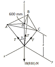
Equation of Equilibrium: Applying the equilibrium equation along the z-axis, with T = 50 N, we have
Σ Fz = 0;
3[(50 N) cos  ] - 10(9.81) N = 0
 = cos-1 (98.1 / 150)
= 49.160
Now,
By geometry shown in free-body diagram,
Tan 49.160 = (600 / s)
s = 519 mm
In this way, three-dimensional problems are solved using equations of equilibrium.
e.g., 4: A 90-lb load is being suspended from a hook as shown in Fig. Below. If the load is being supported by two cables and a spring having a stiffness of k = 500 lb/ft, find the force in the cables and the stretch of the spring for equilibrium. Cable AD lies in the x–y plane and cable AC lies in the x–z plane.
Solution:
Initially, force in spring is determined to determine stretching of spring.
Free-Body Diagram. A point is chosen for all analysis as all the points are concurrent here. The free-body diagram for the problem is shown in Fig. Below.
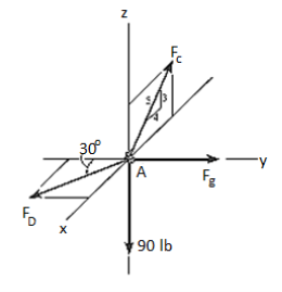
Equations of Equilibrium. We can resolve each force in x, y and z components, and so we can use three scalar equations of equilibrium. Considering components directed along each positive axis as “positive,” we have
Σ Fx = 0
FD sin 30° - (4/5) FC = 0
Σ Fy = 0
-FD cos 30° + FB = 0
Σ Fz = 0
(3/5) FC – 90 lb = 0
Thus, solving the above-mentioned equations, we get,
FC = 150 lb
FD = 240 lb
FB = 207.8 lb
The stretch of the spring is therefore
FB = ksAB
207.8 lb = (500 lb/ft) (sAB)
sAB = 0.416 ft
Thus, the method discussed earlier can be followed as shown in the examples for finding out the unknown quantities in two- and three-dimensional problems using equations of equilibrium.
References:
1. Engineering Mechanics: F. L. Singer
2. Engineering Mechanics: Timoshenko & Young
3. Engineering Mechanics: Bear & Johnston
4. Engineering Mechanics: I. H. Shames
5. Engineering Mechanics: A. Nelson