Unit - 3
Centroids and Moments of Inertia
Second moment of area
The integral ∫ y2 dA defines the second moment of area I about an axis and can be obtained by considering a segment of area δA some distance y from the neutral axis, writing down an expression for its second moment of area and then summing all such strips that make up the section concerned, i.e. integrating. As indicated in the discussion of the general bending equation, the second moment of area is needed if we are to relate the stress produced in a beam to the applied bending moment.
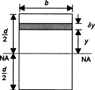
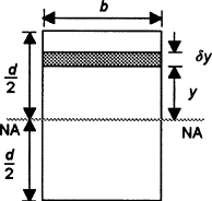
As an illustration of the derivation of a second moment of area from first principles, consider a rectangular cross-section of breadth b and depth d . For a layer of thickness δy a distance y from the neutral axis, which passes through the centroid, the second moment of area for the layer is:
Second moment of area of strip=y2δA=y2b δy
The total second moment of area for the section is thus:
Second moment of area=∫limits from −d/2 to d/2) y2bdy=bd3/12
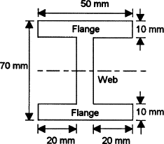
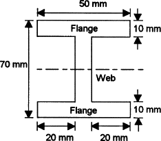
Q. Determine the second moment of area about the neutral axis of the I-section shown in Figure.
Sol:
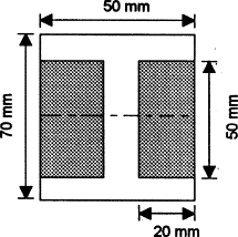
We can determine the second moment of area for such a section by determining the second moment of area for the entire rectangle containing the section and then subtracting the second moments of area for the rectangular pieces ‘missing’
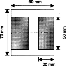
Thus for the rectangle containing the entire section, the second moment of area is given by I = bd3/12 = (50 × 703)/12 = 1.43 × 106mm4. Each of the ‘missing’ rectangles will have a second moment of area of (20 × 503)/12 = 0.21 × 106 mm4. Thus the second moment of area of the I-section is 1.43 × 10⁶ − 2 × 0.21 × 106 = 1.01 × 106mm4
The product of inertia is defined as
The x and y terms inside the integral denote the centroidal position of the differential area measured from the y and x axes, respectively. Similar to moments of inertia discussed previously, the value of product of inertia depends on the position and orientation of selected axes. It is possible for the product of inertia to have a positive, negative, or even a zero value.
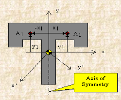
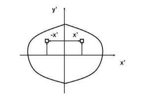
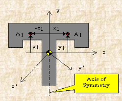
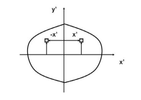
For example, either x or y represents an axis of symmetry, then the product of inertia Ixy would be zero. To see why this is the case, take a look at the figure to the right. Consider the small area A1 to the right of y axis at the distance of x1. Then consider a similar area to the left of this axis of symmetry at the distance of -x1. Since both areas are at the same vertical position from the x-axis, they have the same value of y. The contribution from the left area is -x1yA1 and that from the right is x1yA1 which add up to zero. Since every point on one side of the axis of symmetry has an equal counterpart on the other side, the total value of the integral would be zero.
However, if we were to consider the product of inertia with respect to the x' and y' axes, then Ix'y' would not be zero. We will have more discussion about the product of inertia in the section on principal axes.
For a general three-dimensional body, it is always possible to find 3 mutually orthogonal axes (an x, y, z coordinate system) for which the products of inertia are zero, and the inertia matrix takes a diagonal form. In most problems, this would be the preferred system in which to formulate a problem. For a rotation about only one of these axis, the angular momentum vector is parallel to the angular velocity vector. For symmetric bodies, it may be obvious which axis is principle axis. However, for an irregular-shaped body this coordinate system may be difficult to determine by inspection; we will present a general method to determine these axes in the next section. But, if the body has symmetries with respect to some of the axis, then some of the products of inertia become zero and we can identify the principal axes.
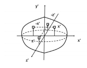
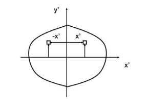
For instance, if the body is symmetric with respect to the plane x’ = 0 then, we will have Ix’y’ = Iy’x’ = Ix’z’ = Iz’x’ = 0 and x’ will be a principal axis. This can be shown by looking at the definition of the products of inertia.
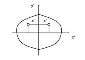
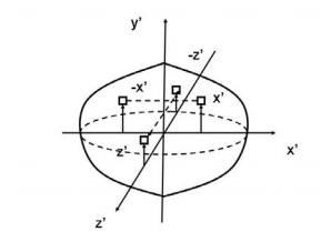
The integral for, say, Ix’y’ can be decomposed into two integrals for the two halves of the body at either side of the plane x’ = 0. The integrand on one half x’y’. will be equal in magnitude and opposite in sign to the integrand on the other half (because x’ will change sign). Therefore, the integrals over the two halves will cancel each other and the product of inertia Ix’y’ will be zero. (As will the product of inertia Ix’z’ ) Also, if the body is symmetric with respect to two planes passing through the center of mass which are orthogonal to the coordinate axis, then the tensor of inertia is diagonal, with Ix’y’ = Ix’z’ = Iy’z’ = 0
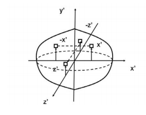
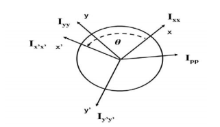
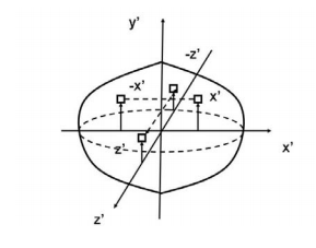
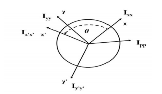
Another case of practical importance is when we consider axisymmetric bodies of revolution. In this case, if one of the axes coincides with the axis of symmetry, the tensor of inertia has a simple diagonal form. For an axisymmetric body, the moments of inertia about the two axis in the plane will be equal. Therefore, the moment about any axis in this plane is equal to one of these. And therefore, any axis in the plane is a principal axis. One can extend this to show that if the moment of inertia is equal about two axis in the plane (IP P = Ixx), whether or not they are orthogonal, then all axes in the plane are principal axes and the moment of inertia is the same about all of them. In its inertial properties, the body behaves like a circular cylinder.
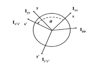
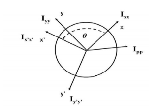
The tensor of inertia will take different forms when expressed in different axes. When the axes are such that the tensor of inertia is diagonal, then these axes are called the principal axes of inertia.
Key takeaways
1) Second moment of area of strip=y2δA=y2b δy
2) Thus for the rectangle containing the entire section, the second moment of area is given by I = bd3/12
Moment of Inertia of Cylinder
The moment of inertia of cylinder about a perpendicular axis passing through its centre is determined by;
Ix = ¼ MR2 + 1/12 ML2
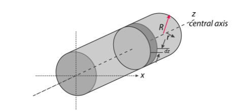
We will look at the derivation of this formula below.
Generally, the derivation involves 3 primary steps. It includes;
- Splitting the cylinder into infinitesimally thin disks and stating the moment of inertia.
- Using both parallel and perpendicular axis theorems to determine the expression.
- Integrating over the length of the cylinder.
1. Cutting the cylinder into infinitesimally thin disks
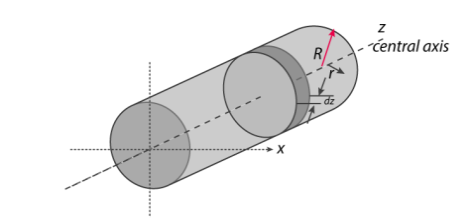
We will consider the cylinder having mass M, radius R, length L and the z-axis which passes through the central axis.
Here,
Density ρ = M / V
Next, we will consider the moment of inertia of the infinitesimally thin disks with thickness dz.
First, we assume that dm is the mass of each disk, We get;
Dm = ρ X Volume of disk
Dm = M / V X (πr2.dz)
We take V = area of circular face X length which is = πr2L. Now we obtain;
Dm = M / πr2L X (πr2.dz)
Dm = M / L X dz
The moment of inertia about the central axis is given as;
Dlz = ½ dmR2
Use of Perpendicular Axis Theorem
We now apply the perpendicular axis theorem which gives us;
Dlz = dlx + dly
Here, if we need to consider that both x and y moments of inertia are equal by symmetry.
Dlx = dly
We need to combine the equations for the perpendicular axis theorem and symmetry. We get;
Dlx = dlz / 2
Now we substitute lz from the equation above.
Dlx = ½ x ½ dmR2
Dlx = ¼ dmR2
Alternatively, for the x-axis, we use the parallel axis theorem to find the moment of inertia. We get;
Dlx = ¼ dmR2 + dmz2
Integration
Now we conduct integration over the length of the cylinder to express the mass element dm in terms of z. We take the integral from z=0 to z=L.
Ix = o∫L dlx
Ix = o∫L ¼ dzR2 + o∫L ¼ z2 m / l dz
Ix = ¼ M / L R2z + M / L Z3 / 3]0L
Since it is a definite form of integral we ignore the constant. We will now have;
Ix = ¼ M / L R2 L + M / 3L 2L3 / 23
Ix = ¼ MR2 + 1/12 ML2
= M [ R2/4 + R2/12]
Imy = M/12 [3R2 + h2]
Similarly, Imx = M/12[3R2 + h2]
As the centroidal axis coincides with axis of cylinder
Imz = 
= 
Therefore, I =1/2 MR2
Moment Of Inertia of Sphere
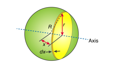
First, we take the moment of inertia of a disc that is thin. It is given as;
I = ½ MR2
In this case, we write it as;
DI (infinitesimally moment of inertia element) = ½ r2dm
Find the dm and dv using;
Dm = p dV
p = moment of a thin disk of mass dm
Dv = expressing mass dm in terms of density and volume
DV = π r2 dx
Now we replace dV into dm. We get;
Dm = p π r2 dx
And finally, we replace dm with dI.
DI = ½ p π r4 dx
The next step involves adding x to the equation. If we look at the diagram we see that r, R and x forms a triangle. Now we will use Pythagoras theorem which gives us;
r2 = R2 – x2
Now if we substitute the values we get;
DI = ½ p π (R2 – x2)2 dx
This leads to:
I = ½ p π -R∫R (R2 – x2)2 dx
After integration and expanding we get;
I = pπ 8/15 R5
Additionally, we have to find the density as well. For that we use;
P (density) = M (mass) / V (volume)
p = M (mass) / (4/3 πR3)
If we substitute all the values;
I = 8/15 π [M / (4/3 πR3)] R5
I = ⅖ MR2
Moment of inertia of Solid Cone
We will take a solid cone where its axis will pass through the centre with radius = r, height = h. We will need to determine the mass though.
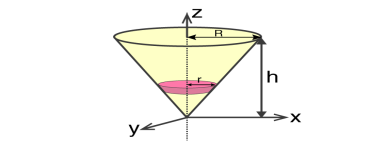
We take the elemental disc whose mass is given by;
Dm = ρ⋅ π r2dz
Density is given as;
ρ = M / V = M / (⅓π R2h)
With this, we will calculate the dm.
Dm = [M / (⅓π R2h)] X π r2dz
Dm = (3M / R2h) Xr2dz
If we consider the similarity of the triangle, then we have;
R / r = h / z
r = R .z / h
Now,
Dm = (3M / R2h )⋅( R2 / h2) ⋅ z2dz
Dm = (3M / h3 ). z2dz
If we consider z-axis, the moment of inertia of the elemental disk will be;
DI = ½ dmr2
DI = ½ ⋅(3M / h3) . z2 ⋅(z2 R2 / h2) dz
DI = 3 / 2 ⋅ M R2 / h5 X z4dz
Now we will follow the integration process. Here;
I = 3 / 2 ⋅ M R2 / h5 o∫h z4dz
I = 3 / 2 ⋅ M R2 / h5 [z5 / 5 ]oh
I = 3 / 2 ⋅ M R2 / h5 ⋅ h5 / 5
Therefore, I = 3/10 MR2
Q. Determine moment of Inertia for  section about x & y axis as shown in figure.
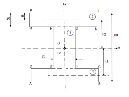
M.I. If this rectangle about xx and yy axis will be,         |     = 106666666.7 mm4 Consider rectangle ABCD area ③             = 213.64 
|
      |
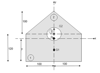
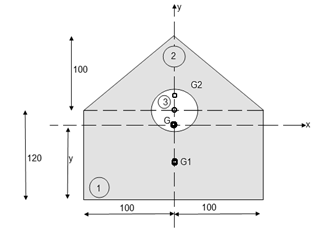
Q: Determine the moment of inertia of shaded area as shown in figure about its centroid as axis.
Ans:
As this figure is symmetrical about
Y axis
X = 100 mm
Y = 
Where,
Area ① = rectangle
Area ② = triangle
Area ③ = circle

Y = 79.95 mm
 to find M.I. Of shaded portion , let G is the centroid of shaded area which is at y = 79.95 mm from base.
 of shaded portion @ x-x axis passing through its centroid G will be,
 x-x) +
 x-x) –
 x-x axis)
 1 +
1 +  2
2 3
3
= ( G1 + A1h12) +
  G2 + A2h22) -
  G3 + A3h32)
=  +
+  -60
-60 ] +
] +
 +
+  –
–


 84329013.21 mm4
 of shaded portion about y-y axis passing through its centroid G will be,
 y-y) +
 y-y axis) –
 y-yaxis)
 1 +
1 +  2
2 3
3
= 

= 80000000 + 16666666.67 – 3220623.34
 93446043.33 mm4
The Transfer theorem is also known as Parallel Axis Theorem.
When we calculated the area and mass moments of inertia via integration, one of the first things we had to do was to select a point or axis we were going to take the moment of inertia about. We then measured all distances from that point or axis, where the distances were the moment arms in our moment integrals. Because the centroid of a shape is the geometric center of an area or volume, the average distance to any one point in a body is at a minimum.
If we pick a different point or axis to take the moment of inertia about then on average all the distances in our moment integral will be a little bit bigger Specifically the further we move from the centroid, the larger the average distances become.
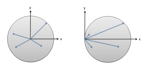
Fig: The distance used in our moment integrals depends on the point or axis chosen. These distances will be at a minimum at the centroid and will get larger as we start further from the centroid.
Though this complicates our analysis, the nice thing is that the change in the moment of inertia is predicable. It will always be at a minimum when we take the moment of inertia about the centroid, or an axis going through the centroid. This minimum, which we will call Ic is the value we will look up in our moment of inertia table. From this minimum, or unadjusted value, we can find the moment of inertia value about any point Ip by adding an an adjustment factor equal to the area times distance squared for area moments of inertia, or mass times distance squared for mass moments of inertia.
IxxP=IxxC+A∗r2
IxxP=IxxC+m∗r2
This adjustment process with the equations above is the parallel axis theorem. The area or mass terms simply represent the area or mass of the part you are looking at, while the distance (r) represents the distance we are moving the axis we are taking the moment of inertia about. This may be a vertical distance, a horizontal distance, or a diagonal depending on the axis the moment or inertia is about.
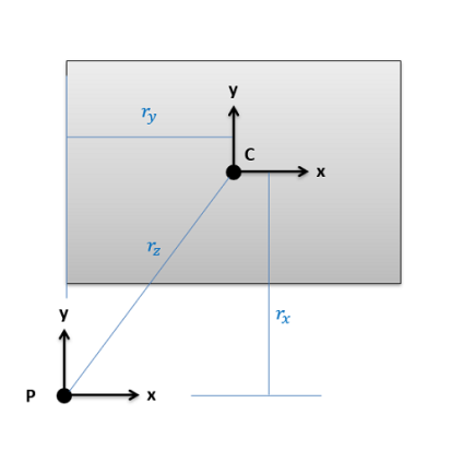
Fig: The distance (r) in the Parallel Axis Theorem represents the distance we are moving the axis we are taking the moment or intent about.
Say we are trying to find the moments of inertia of the rectangle above about point P. We would start by looking up Ixx, Iyy, and Jzz about the centroid of the rectangle (C) in the moment of inertia table. Then we would add on an area times distance squared term to each to find the adjusted moments of inertia about P. The distance we are moving the x axis for Ixx is the vertical distance rx, the distance we are moving the y axis for Iyy is the horizontal distance ry, and the distance we would move the z axis (which is pointing out of the page) for Jzz is the diagonal rz. Center of mass adjustments follow a similar logic, using mass times distance squared, where the distance represents how far you are moving the axis of rotation in three dimensional Spaces
Using the Method of Composite Parts to Find the Moment of Inertia
To find the moment of inertia of a body using the method of composite parts, you need to start by breaking your area or volume down into simple shapes. Make sure each individual shape is available in the moment of inertia table, and you can treat holes or cut-out’s as negative area or mass.
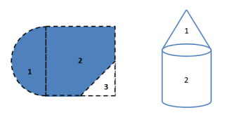
Fig: Start by breaking down your area or volume into simple parts and number those shapes. Holes or cut-outs will count as negative areas or masses.
Next you are going to create a table to keep track of values. Devote a row to each part that your numbered earlier, and include a final "total" row that will be used for some values. Most of the work of the method of composite parts is filling in this table The columns will vary slightly with what you are looking for, but you will generally need the following.
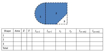
Most work in the method of composite parts will revolve around filling out a table such as this one. This table contains the rows and columns necessary to find the rectangular area moments of inertia (Ixx and Iyy) for this composite body.
- The area or mass for each piece (area for area moments of inertia or mass for mass moments of inertia). Remember cut outs should be listed as negative areas or masses.
- The centroid or center of mass locations (X, Y and possibly Z coordinates). Most of the time, we will be finding the moment of inertia about centroid of the composite shape, and if that is not explicitly given to you, you will need to find that before going further. For more details on this, see the page "Centroids and Center of Mass via Method of Composite Parts".
- The moment of inertia values about each shape's centroid. To find these values you will plug numbers for height, radius, mass, etc. into formulas on the moment of inertia table. Do not use these formulas blindly though as you may need to mentally rotate the body, and thus switch equations, if the orientation of the shape in the table does not match the orientation of the shape in your diagram.
- The adjustment distances (r) for each shape. For this value you will want to determine how far the x-axis, y-axis, or z-axis moves to go from the centroid of the piece to the overall centroid, or point you are taking the moment of inertia about. To calculate these values generally, you will be finding the horizontal, vertical, or diagonal distances between piece centroids and the overall centroids that you have listed earlier in the table. See the parallel axis theorem section of this page earlier for more details.
- Finally, you will have a column of the adjusted moments of inertia. Take the original moment of inertia about the centroid, then simply add your area times r squared term or mass times r squared term for this adjusted value.
The overall moment of inertia of your composite body is simply the sum of all of the adjusted moments of inertia for the pieces, which will be the sum of the values in the last column (or columns if you are finding the moments of inertia about more than one axis).
Product of inertia
In addition to the moment of inertia, the product of inertia is commonly used. Here only the product of the area is defined and discussed. The product of inertia defined as
Ixixj=∫AxixjdA
For example, the product of inertia for xx and yy axes is
Ixy=∫AxydA
Product of inertia can be positive or negative value as oppose the moment of inertia. The calculation of the product of inertia isn't different much for the calculation of the moment of inertia. The units of the product of inertia are the same as for moment of inertia.
Transfer of Axis Theorem
Same as for moment of inertia there is also similar theorem.
I x′y′ = ∫Ax′y′dA= ∫A(x+Δx)(y+Δy)dA
Expanding equation above results in
I x′y′ = ∫AxydA+ ∫AxΔydA+ ∫AΔxydA+ ∫AΔxΔydA
The final form is
I x′y′= Ixy+ ΔxΔydA
There are several relationships should be mentioned
I xy=I yx
Symmetrical area has zero product of inertia because integration of odd function (asymmmertial function) left part cancel the right part.
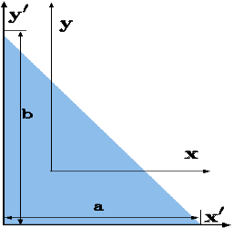
Fig. Product of inertia
Polar Moment of Inertia is a measure of an object’s capacity to oppose or resist torsion when some amount of torque is applied to it on a specified axis. Torsion, on the other hand, is nothing but the twisting of an object due to an applied torque. Polar moment of inertia basically describes the cylindrical object’s (including its segments) resistance to torsional deformation when torque is applied in a plane that is parallel to the cross-section area or in a plane that is perpendicular to the object’s central axis.
If we put it in simple terms polar moment of inertia is the resistance offered by a beam or shaft when it is being distorted by torsion. This opposition usually arises from the cross-sectional area and it should be noted that it does not depend on the material composition. If the polar moment of inertia is of higher magnitude then the torsional resistance of the object will also be greater. More torque will be required to turn the shaft at an angle.
Nonetheless, it is one of the main aspects of the area moment of inertia and we can use the perpendicular axis theorem to link the two quantities.
Polar Moment Of Inertia Formula
Polar Moment of Inertia is also called the second polar moment of area. It is usually denoted by IZ. However, sometimes J or JZ is also used. Polar Moment of Inertia can be represented mathematically with the given formula;
I or J = r2 dA
Here,
r = distance to the element dA.
Units
The dimension unit of polar moment of inertia is length to the power of four (L4); The SI unit of this property is, meters to the fourth power (m4). In the imperial unit system, it is inches to the fourth power (in4).
Types of Cross-section Polar Moment of Inertia
There are three main types of cross-section polar moment of inertia. They are as follows.

1. Hollow Shaft
To determine the polar moment of inertia we use;
Jhollow = π(R04–R14)/2
R1 and Ro = inner and outer radius of the hollow shaft.
2. Thin-Walled Shaft
To determine the polar moment of inertia we use;
Jthin = 2πt [R0+Ri/2]3
t = thickness of the thin-walled shaft.
3. Solid Circular Shaft
To determine the polar moment of inertia we use the following formula;
Jsolid = πR4/2
R = radius of the circular shaft.
Uses and Limitations
Generally, the second polar moment of area is used in determining the angular displacement of a body that is subjected to torque or to calculate the torsion force on a circular body. As for the limitation, the polar moment of inertia is not suitable for analysing shafts and beams with non-circular cross-sections. This is mainly because objects with non-circular cross-sections tend to warp when torque is applied and it further leads to out-of-plane deformations.
Shape | Area(a) | Moment of Inertia | Radius of gyration (r) | Polar moment of Inertia (J) |
Rectangle 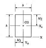 | A = bh | IXa = bh3/12 Iya = hb3/12 IX = bh3/3
| rx0 = h/12 ry0 = b/12 rx = h/3
| ICG = hb/12 (b2 + h2) |
Triangle 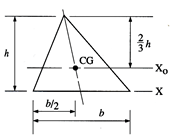 | A = bh/2 | IXa = bh3/36 IX = bh3/12
| rx0 = h/18 rx = h/6
|
|
Circle 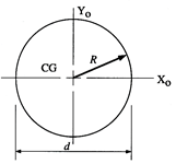 | A = πd2/4 = 0.7854 d2 | Ix0 = Iy0 = πd2/64 | Γx0 = Γy0 = d/4 | ICG = πd2/32 |
Semicircle 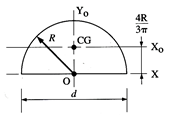 | A = πR2/4 = 1.571 R2 | Ix0 = 01098 R4 Iy0 = Ix = πR4/8 | Γx0 = 0.264 R Γy0 = Γx = R/2 | ICG = Ix0 + Iy0 = 0 I0 = πR4/4 |
Hollow circle 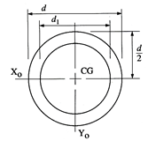 | A =  | Ix0 =  Iy0 = Ix0 | Γx0 =  Γy0 = Γx0 | ICG =  |
Hollow rectangle 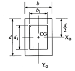 | A = bd – b1d1 | Ix0 =  Iy0 =  | Γx0 =  Γy0 =  | ICG = Ix0 + Iy0 |
Quarter circle 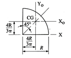 | A = πR2/4 | Ix0 = Iy0 = 0.05 Ix = πR4/16 | Γx0 = Γy0 = 0.2∈ rx = 0.5 R | ICG = 0.1098 R4 |
Principal moments of inertia and principal axes
For a general three-dimensional body, it is always possible to find 3 mutually orthogonal axis (an x, y, z coordinate system) for which the products of inertia are zero, and the inertia matrix takes a diagonal form. In most problems, this would be the preferred system in which to formulate a problem. For a rotation about only one of this axis, the angular momentum vector is parallel to the angular velocity vector. For symmetric bodies, it may be obvious which axis is principle axis. However, for an irregular-shaped body this coordinate system may be difficult to determine by inspection; we will present a general method to determine these axes in the next section. But, if the body has symmetries with respect to some of the axis, then some of the products of inertia become zero and we can identify the principal axes.
For instance, if the body is symmetric with respect to the plane x’ = 0 then, we will have Ix’y’ = Iy’z’ = Ix’z’ = Iz’x’ =0and x’ will be a principal axis. This can be shown by looking at the definition of the products of inertia.
The integral for, say,Ix’y’ can be decomposed into two integrals for the two halves of the body at either side of the plane x’ = 0. The integrand on one halfx’ y’ will be equal in magnitude and opposite in sign to the integrand on the other half (because x’ will change sign). Therefore, the integrals over the two halves will cancel each other and the product of inertia Ix’y’ will be zero. (As will the product of inertia Ix’z’) Also, if the body is symmetric with respect to two planes passing through the center of mass which are orthogonal to the coordinate axis, then the tensor of inertia is diagonal, with Ix’y’ = Ix’z’ = Iy’z’ = 0
Another case of practical importance is when we consider axisymmetric bodies of revolution. In this case, if one of the axis coincides with the axis of symmetry, the tensor of inertia has a simple diagonal form. For an axisymmetric body, the moments of inertia about the two axis in the plane will be equal. Therefore, the moment about any axis in this plane is equal to one of these. And therefore, any axis in the plane is a principal axis. One can extend this to show that if the moment of inertia is equal about two axis in the plane (IP P = Ixx), whether or not they are orthogonal, then all axes in the plane are principal axes and the moment of inertia is the same about all of them. In its inertial properties, the body behaves like a circular cylinder.
The tensor of inertia will take different forms when expressed in different axes. When the axes are such that the tensor of inertia is diagonal, then these axes are called the principal axes of inertia.
The Search for Principal Axes and Moments of Inertia as an Eigenvalue Problem
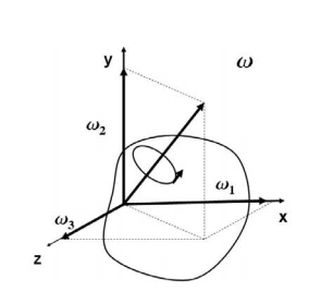
Three orthogonal principal axes of inertia always exist even though in bodies without symmetries their directions may not be obvious. To find the principle axis of a general body consider the body shown in the figure that rotates about an unknown principal axis. The total angular momentum vector is r in the direction of the principle axis. For rotation about the principal axis, the angular momentum and the angular velocity are in the same direction.
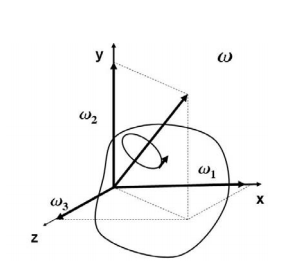
We seek a coordinate axes x, y and z, about which a rotation ωx, ωy and ωz, which is aligned with this coordinate direction, will be parallel to the angular momentum vector and related by the equation

We then express the general form for angular momentum vector in components along the x, y and z axis in term of the components of ω along these axes using the general form of the inertia tensor in the x, y, z system, we have

To obtain the special directions of that is aligned with a principal axis, we equate these two expressions.

At this point in the process we know the inertia tensor in an arbitrary x, y, and z system and are seeking the special orientation of ω which will align the angular momentum HG with the angular velocity ω. Collecting terms from equation(11) on the left-hand side, we obtain

Resulting in the requirement that

The structure of the solution for finding the principal axes of inertia and their magnitudes is a characteristic value problem. The three eigen values give the directions of the three principal axis, and the three eigenvectors give the moments of inertia with respect to each of these axis. In principal directions, the inertia tensor has the form

Where we will write Ix = Ixx, Iy = Iyy and Iz = Izz. Also, in principal axes we will then have
HG = Ixxi + Iyyj + Izzk
Q: A body of weight 50 N is along rough horizontal plane A pull of 18 N acting at an angle of 140 with the horizontal find coefficient of static friction.

Ans.
Considering the equilibrium of block

 18 Cos 14 – Fs = 0
 Fs = 17.46 N

RN + 18 Sin 14 – 50 = 0
RN = 45.64 N
As Fs =  S RN
S RN
17.46 =  S
S  45.64
45.64
 S = 0.386
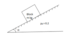
Q: A block of mass m rests on frictional plane which makes an angle  with horizontal as shown if the coeff. Of friction between the block & frictional plane is 0.2, determine angle
  for limiting friction.
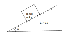
Ans:
For limiting friction
Tan  tan
tan  S =
S =  S
S
 tan-1
tan-1 S
S
 tan-1
tan-1
 11.310
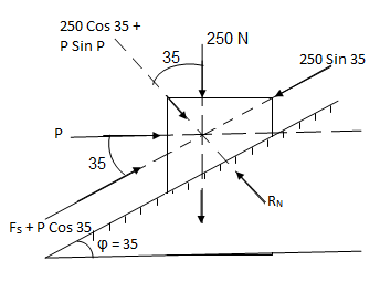
Q: Determine whether the block shown is in equilibrium and find the magnitude and direction of friction force when  = 350 and P = 100 N
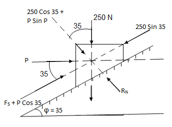
Ans.
Let us select inclined plane as x-x axis & perpendicular to plane as y-y axis
Let Fs = static frictional force which is required to maintain equilibrium.
 -------- resolving force along x-axis
 Fs + 100 Cos 35 – 250 Sin 35 = 0
 Fs – 61.48 = 0
 Fs = 61.48 N ----- frictional force
 -------- resolving force along y-axis
 -(250 Cos 35 + P Sin 35) + RN = 0
 -250 Cos 35 – 100 Sin 35 + RN = 0
-262.15 + RN = 0
 RN = 262.15 N -------- normal reaction
Maximum frictional force can be developed is given by
Fs max =  S
S RN = 0.3
  262.15
Fs max = 78.65 N
As frictional force required to maintain equilibrium (61.48 N) is less than max. Frictional force,
 Equilibrium will be maintained
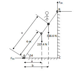
Q. Uniform ladder AB has a length of 8 m and mass 24 kg end A is on horizontal floor and end B rests against vertical wall. A man of mass of 60 kg has to climb this ladder. At what position from the base, will be induce the slipping of ladder.
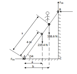
Ans.
Take  S = 0.34 at all contact surface.
Weight of man = 60 9.81 =588.6 N
Weight of ladder 
AB = 8 m
Impending motion
 Ac = 8 Cos 54
 BC = 8 Sin 54
 ɑ = 2.35 m
 b = x Cos 54
 FSA =
FSA =  S
S  RNA
RNA
 FSB =
FSB =  S
S  RNB
RNB
Considering the equilibrium of ladder
 FX = 0
             |
 

From eqn …..1
RNB = 0.34 

|
Taking moment about point A,
 MA = 0

 SB
SB Cos 54) – (RNB
 8 Sin 54) = 0
 (
( S
S  RNB
RNB  4.7) – (6.47 RNB) = 0
 1.598 RNB – 6.47 RNB = 0
 345.97x – 8.068 RNB = 553.284
 345.97x – 8.068
  251.14 = 553.284
 345.97x = 1472.913
X = 4.257 m
At X = 4.257 m from point A, along the ladder, man can climb without slipping.
Beyond this distance, ladder will be slipping.
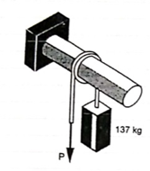
Q. A 137 kg block is supported by a rope which Is wrapped 1.5 times around a horizontal Rod knowing that coeff. Of static friction Between rope and rod is 0.15, determine the range of values of P for which Equilibrium is maintained.
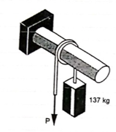
Ans.
Weight of block = 
Angle of contact = LAP Angle


A) Case I: when P > 1343.97 N
Force P tends to move the rope down ward and block moves upward. Thus the part rope on which force P is acting is height side and rope to which block is attached is slack side.
 =
=  =
= 
 P = 5525.34 N
B) Case II: when P < 1343.97 N
 force P is less than 1343.97 N, so block will move down ward & the side rope on which P acts will move upward.
 Rope side to which block is attached is tight side and another side is slack side.
 =
=  =
= 
 P = 326.92 N
 range of P for equilibrium is 326.92 N
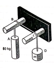
Q. Two cylinders are connected by a rope that passes Over two fixed rods as shown. Knowing that the Coefficient of static friction between the rope and the rods is 0.40. Determine the range of the mass m of cylinder D for which equilibrium is maintained.
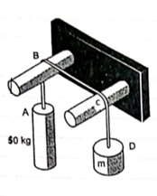
Ans.
Weight of cylinder = 50  9.81 = 490.5 N
Lap angle = 
 S = 0.40
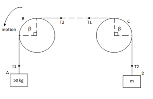
A) Case I:
Weight of cylinder A > weight of cylinder B.
In this case cylinder A will tends to move downward while B will tends to move upward
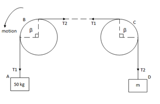
Consider part AB of the Rope as AB rope is moving down,
Tension in hight side T1 = 
Tension in slack side = T2 = unknown.
 =
=  =
=  = 1.874
 = T2
= T2
 T2 = 261.74 N
Consider part CD, of the rope. As rope CD is moving upward,
Tension in tight side T1 = T2 of rope AB
Tension in tight side, T1 = 261.74 N
Tension in slack side = T2 = (m  9.81)
9.81)
    |   |
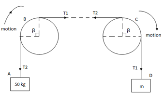
B) Case II:
Weight of cylinder A < weight of cylinder B
In this case cylinder a will tends to move upward while cylinder B will tends to move downward
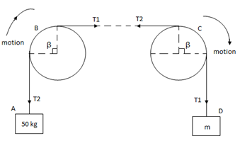
Consider part AB of the rope moving upwards
Tension in slack side = side A = 
    |   |
Consider part CD of rope, Rope CD is moving downwards
Tension in tight side = T1 = (m 9.81) N
Tension in slack side = T2 = T1 of rope AB = 919.197 N
    |   |
Range of mass m for equilibrium to be maintained is
14.23 kg  m
m 175.59 kg
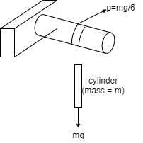
Q. A Force P = mg/6 is required to lower the cylinder with card making 1.25 turns around the fixed shaft. Determine the coeff. Of friction “ S” between the card and the shaft
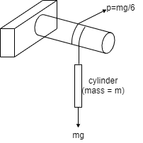
Ans.
Refer the figure
Lap angle

= 2.5 radians
For flat belt,
 =
= 
 =
= 
 6
6 
 1.79 =
  S
S 2.5
2.5
 S = 0.23
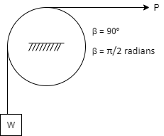
Q. Determine the range of P for the equilibrium of block of weight W as shown in fig. The coeff. Of friction between rope and pulley is 0.2
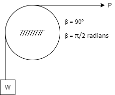
Ans.
Case I: when P is max.
 =
= 
 =
= 
 Pmax = 1.369 w
Case II: when P is min.
 =
= 

 Pmin = 0.73 w
For equilibrium P must be between 0.73  P
P  1.369 w
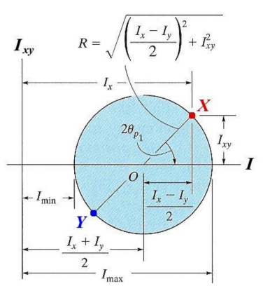
Mohr's Circle for Mom. Of Inertia
- When all possible moments and products of inertia for a shape are plotted on a graph, the resulting graph is a circle.
- This graph makes it easy to find any moment or product of inertia for a shape that we want. All we have to do is use the geometrical properties of a circle.
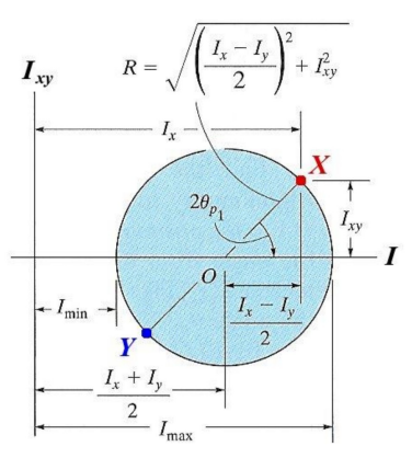
- Ix and ly are plotted on horizontal axis
- Ixy is plotted on vertical axis
- Plot point 'X 1st (Ix, lxy)
- 'Y' will be on opposite side as (Iy, -lxy) (note signs of lxy)
- Now you have two points
- Draw the circle through these points
- Find any other points you need (usually Imin and Imax)
Finding Imin and Imax
- Once the circle is drawn (see previous slide) locate the center point (shown here as O)
- Form a right triangle by dropping a vertical line from point X to horizontal axis.
- Use this triangle to find the radius of the circle (hypotenuse) and the angle shown as 2
- Imin and Imax are simply the center plus or minus the radius.
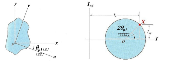
Finding Theta
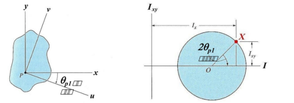
- It can be important to know the orientation (with respect to the x-y axis system) of a physical object for a given moment of inertia.
- Rotating the object's coordinate system through any angle will correspond to an angle of 2 on Mohr's Circle.
- Theta () is always measured:
- the same rotational direction on both the object and the graph.
- from point X on the graph and from the x-axis on the object.
The principle of virtual work was proposed by the Swiss mathematician Jean Bernoulli in the eighteenth century. It provides an alternative method for solving problems involving the equilibrium of a particle, a rigid body, or a system of connected rigid bodies.
The definitions of the work of a force and a couple can be presented in terms of the actual movements which are expressed by differential displacements having values of  and
and  . Consider now an imaginary or virtual movement of a body in static equilibrium, which indicates a displacement or rotation that is assumed and does not actually exist. These movements are first-order differential quantities and will be denoted by the symbols
  and
and  (delta r and delta
  ), respectively. The virtual work done by a force having a virtual displacement
  is
is

Similarly, when a couple undergoes a virtual rotation  in the plane of the couple forces, the virtual work is

According to the principle of virtual work if a body is in equilibrium, then virtual displacement of the body is zero for all the algebraic sum of the virtual work which is done by all the forces and moments of couple that are acting on the body. Thus,

For example, consider the free-body diagram of the particle (ball) that rests on the floor, Fig. Below. If we “imagine” the ball to be displaced downwards a virtual amount  then the weight does positive virtual work
  , and the normal force does negative virtual work
  , For equilibrium the total virtual work must be zero, so that

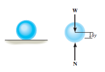
As seen from the above example, no added advantage is gained by solving particle and rigid-body equilibrium problems using the principle of virtual work. This is because for each application of the virtual-work equation, the virtual displacement, common to every term, factors out, leaving an equation that could have been obtained in a more direct manner by simply applying an equation of equilibrium.
A particle of mass m is acted upon by a number of forces f1,f2….fN. Suppose the particle undergoes a virtual displacement δu to reiterate, these impressed forces fido not cause the particle to move, one imagines it to be incorrectly positioned a little away from the true equilibrium position.
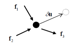
If the particle is moving with an acceleration a, the quantity -ma is treated as an inertial force. The total virtual work is then (each term here is the dot product of two vectors)
δW = (
Now if the particle is in equilibrium by the action of the effective (impressed plus inertial) force then δW = 0
This can be expressed as follows:
The principle of virtual work (or principle of virtual displacements) if a particle is in equilibrium under the action of a number of forces (including the inertial force) the total work done by the forces for a virtual displacement is zero.
Alternatively, one can define the external virtual work δWest =  , Wext and the virtual kinetic energy δK = ma. δu in which case the principle takes the form δWest = δK (compare with the work-energy principle
In the above, the principle of virtual work was derived using Newton’s second law. One could just as well regard the principle of virtual work as the fundamental principle and from it derive the conditions for equilibrium. In this case one can say that the principle of virtual work (or principle of virtual displacements)
a particle is in equilibrium under the action of a system of forces (including the inertial force) if the total work done by the forces is zero for any virtual displacement of the particle. The term kinematically admissible displacement is used to mean one that does not violate the constraints, and hence one arrives at the version of the principle which is often used in practice:
The principle of virtual work (or principle of virtual displacements):a particle is in equilibrium under the action of a system of forces (including the inertial force) if the total work done by the forces (excluding reaction forces) is zero for any kinematic ally admissible virtual displacement of the particle.
Key takeaways
1) The virtual work done by a force having a virtual displacement  is
is

Beam:
It is horizontal structural member on which different types of loads can be supported. It takes load from floor or roof & transfers to column.
The beam may be sometimes constructed in the inclined position for architectural point of view.
Types of Beam
- Simply supported beam –
A beam which is just resting on the supports at the end without any connection is known as simply supported beam. It is generally used for vertical landing system.

2. Overhanging Beam –
A beam which is supported at the intermediate point other than ends is called as overhanging beam. Here portion of beam is extended beyond the support

a) (singly overhanging beam)

b) (doubly overhanging beam)
3. Cantilever Beam –
A beam which is fixed at one end is called as cantilever beam

Here, there are three reactions components:
- Vertical reaction at A (RVA)
- Horizontal reaction at A (RHA)
- Fixing moment at A (MA)
We can assume any direction for above components.
4. Continuous Beam:
A beam having more than two support is called as continuous beam.

5. Compound Beam:
When two or more beams are joined together by using internal hinge; or when one beam rests over another beam by using internal roller, then such beam is called as compound beam.

Trusses are simply defined as triangulation of members to make the stabilized structure. Triangulation is the stable configuration mathematically. Generally, a truss has the members called as top chord, bottom chord, vertical chord and diagonal chord. The main functions of the trusses are:
- Carrying the loads from the over structures
- Providing adequate lateral stability to the entire structure
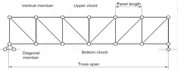
There are some basic assumptions in the designing process. It should be clarified that the construction of the trusses should conform with the design assumptions to avoid the unwanted failures due to the dispersion of the forces and loads.
Following are the assumptions in truss design.
- Truss members will carry only the axial forces
- The nodes i.e. the connections of the members are designed as pinned joints so that moments won’t be transferred to the members of the truss
- All the external loads and the reactions are act only on the nodes
- Generally, the truss should be in a plane.
- Typically the members of the trusses are made as I sections, angles, T sections, Tube sections, Square sections and channel sections. I sections are more preferable as an optimized section in terms of the structural forces.
Types of Trusses
- Simple truss – indicates a single triangular truss. These trusses are most often used as the roof trusses.
- Planar truss – as the name implies it is a two-dimensional truss. If all the members and the nodes are in a planar surface, then this truss is a planar truss.
- Space frame truss – Contrast to planar truss, the members and the nodes are located in the three-dimensional space. Electrical and telecom towers are the one of the simplest examples that we are seeing in the day-to-day life.
Simple Truss: It is possible to create a simple truss by joining three bars together to form a triangle. We can increase the size of the truss by adding two more members with an additional joint. By repeating this process, we can develop simple trusses with different shapes as shown below. The triangular building block assures internal stability of the truss structure as it is increased in size.

Although it is possible to have non-triangular cells in a simple truss, internal stability will not be guaranteed in that case.
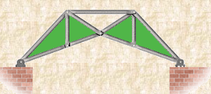
Compound Truss: A compound truss is made up of simple trusses joined together to form a larger truss. The figure below shows a compound truss consisting of two simple trusses joined by a common joint and a bar. It is also possible to have multiple simple trusses joined together to create a larger compound truss. The connection of simple trusses then becomes a design issue determined based on the size of the resulting compound truss. Compound trusses are commonly used to support loads over long spans as in bridges.
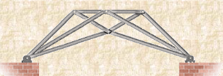
Complex Truss: A complex truss uses a general layout of members different from that used in simple and compound trusses. It often incorporates overlapping members.
Key takeaways
1) Simple truss – indicates a single triangular truss. These trusses are most often used as the roof trusses.
2) Planar truss – as the name implies it is a two dimensional truss. If all the members and the nodes are in a planar surface, then this truss is a planar truss
References:
1. Engineering Mechanics: F. L. Singer
2. Engineering Mechanics: Timoshenko & Young
3. Engineering Mechanics: Bear & Johnston
4. Engineering Mechanics: I. H. Shames
5. Engineering Mechanics: A. Nelson
Unit - 3
Centroids and Moments of Inertia
Second moment of area
The integral ∫ y2 dA defines the second moment of area I about an axis and can be obtained by considering a segment of area δA some distance y from the neutral axis, writing down an expression for its second moment of area and then summing all such strips that make up the section concerned, i.e. integrating. As indicated in the discussion of the general bending equation, the second moment of area is needed if we are to relate the stress produced in a beam to the applied bending moment.
As an illustration of the derivation of a second moment of area from first principles, consider a rectangular cross-section of breadth b and depth d . For a layer of thickness δy a distance y from the neutral axis, which passes through the centroid, the second moment of area for the layer is:
Second moment of area of strip=y2δA=y2b δy
The total second moment of area for the section is thus:
Second moment of area=∫limits from −d/2 to d/2) y2bdy=bd3/12
Q. Determine the second moment of area about the neutral axis of the I-section shown in Figure.
Sol:
We can determine the second moment of area for such a section by determining the second moment of area for the entire rectangle containing the section and then subtracting the second moments of area for the rectangular pieces ‘missing’
Thus for the rectangle containing the entire section, the second moment of area is given by I = bd3/12 = (50 × 703)/12 = 1.43 × 106mm4. Each of the ‘missing’ rectangles will have a second moment of area of (20 × 503)/12 = 0.21 × 106 mm4. Thus the second moment of area of the I-section is 1.43 × 10⁶ − 2 × 0.21 × 106 = 1.01 × 106mm4
The product of inertia is defined as
The x and y terms inside the integral denote the centroidal position of the differential area measured from the y and x axes, respectively. Similar to moments of inertia discussed previously, the value of product of inertia depends on the position and orientation of selected axes. It is possible for the product of inertia to have a positive, negative, or even a zero value.
For example, either x or y represents an axis of symmetry, then the product of inertia Ixy would be zero. To see why this is the case, take a look at the figure to the right. Consider the small area A1 to the right of y axis at the distance of x1. Then consider a similar area to the left of this axis of symmetry at the distance of -x1. Since both areas are at the same vertical position from the x-axis, they have the same value of y. The contribution from the left area is -x1yA1 and that from the right is x1yA1 which add up to zero. Since every point on one side of the axis of symmetry has an equal counterpart on the other side, the total value of the integral would be zero.
However, if we were to consider the product of inertia with respect to the x' and y' axes, then Ix'y' would not be zero. We will have more discussion about the product of inertia in the section on principal axes.
For a general three-dimensional body, it is always possible to find 3 mutually orthogonal axes (an x, y, z coordinate system) for which the products of inertia are zero, and the inertia matrix takes a diagonal form. In most problems, this would be the preferred system in which to formulate a problem. For a rotation about only one of these axis, the angular momentum vector is parallel to the angular velocity vector. For symmetric bodies, it may be obvious which axis is principle axis. However, for an irregular-shaped body this coordinate system may be difficult to determine by inspection; we will present a general method to determine these axes in the next section. But, if the body has symmetries with respect to some of the axis, then some of the products of inertia become zero and we can identify the principal axes.
For instance, if the body is symmetric with respect to the plane x’ = 0 then, we will have Ix’y’ = Iy’x’ = Ix’z’ = Iz’x’ = 0 and x’ will be a principal axis. This can be shown by looking at the definition of the products of inertia.
The integral for, say, Ix’y’ can be decomposed into two integrals for the two halves of the body at either side of the plane x’ = 0. The integrand on one half x’y’. will be equal in magnitude and opposite in sign to the integrand on the other half (because x’ will change sign). Therefore, the integrals over the two halves will cancel each other and the product of inertia Ix’y’ will be zero. (As will the product of inertia Ix’z’ ) Also, if the body is symmetric with respect to two planes passing through the center of mass which are orthogonal to the coordinate axis, then the tensor of inertia is diagonal, with Ix’y’ = Ix’z’ = Iy’z’ = 0
Another case of practical importance is when we consider axisymmetric bodies of revolution. In this case, if one of the axes coincides with the axis of symmetry, the tensor of inertia has a simple diagonal form. For an axisymmetric body, the moments of inertia about the two axis in the plane will be equal. Therefore, the moment about any axis in this plane is equal to one of these. And therefore, any axis in the plane is a principal axis. One can extend this to show that if the moment of inertia is equal about two axis in the plane (IP P = Ixx), whether or not they are orthogonal, then all axes in the plane are principal axes and the moment of inertia is the same about all of them. In its inertial properties, the body behaves like a circular cylinder.
The tensor of inertia will take different forms when expressed in different axes. When the axes are such that the tensor of inertia is diagonal, then these axes are called the principal axes of inertia.
Key takeaways
1) Second moment of area of strip=y2δA=y2b δy
2) Thus for the rectangle containing the entire section, the second moment of area is given by I = bd3/12
Moment of Inertia of Cylinder
The moment of inertia of cylinder about a perpendicular axis passing through its centre is determined by;
Ix = ¼ MR2 + 1/12 ML2
We will look at the derivation of this formula below.
Generally, the derivation involves 3 primary steps. It includes;
- Splitting the cylinder into infinitesimally thin disks and stating the moment of inertia.
- Using both parallel and perpendicular axis theorems to determine the expression.
- Integrating over the length of the cylinder.
1. Cutting the cylinder into infinitesimally thin disks
We will consider the cylinder having mass M, radius R, length L and the z-axis which passes through the central axis.
Here,
Density ρ = M / V
Next, we will consider the moment of inertia of the infinitesimally thin disks with thickness dz.
First, we assume that dm is the mass of each disk, We get;
Dm = ρ X Volume of disk
Dm = M / V X (πr2.dz)
We take V = area of circular face X length which is = πr2L. Now we obtain;
Dm = M / πr2L X (πr2.dz)
Dm = M / L X dz
The moment of inertia about the central axis is given as;
Dlz = ½ dmR2
Use of Perpendicular Axis Theorem
We now apply the perpendicular axis theorem which gives us;
Dlz = dlx + dly
Here, if we need to consider that both x and y moments of inertia are equal by symmetry.
Dlx = dly
We need to combine the equations for the perpendicular axis theorem and symmetry. We get;
Dlx = dlz / 2
Now we substitute lz from the equation above.
Dlx = ½ x ½ dmR2
Dlx = ¼ dmR2
Alternatively, for the x-axis, we use the parallel axis theorem to find the moment of inertia. We get;
Dlx = ¼ dmR2 + dmz2
Integration
Now we conduct integration over the length of the cylinder to express the mass element dm in terms of z. We take the integral from z=0 to z=L.
Ix = o∫L dlx
Ix = o∫L ¼ dzR2 + o∫L ¼ z2 m / l dz
Ix = ¼ M / L R2z + M / L Z3 / 3]0L
Since it is a definite form of integral we ignore the constant. We will now have;
Ix = ¼ M / L R2 L + M / 3L 2L3 / 23
Ix = ¼ MR2 + 1/12 ML2
= M [ R2/4 + R2/12]
Imy = M/12 [3R2 + h2]
Similarly, Imx = M/12[3R2 + h2]
As the centroidal axis coincides with axis of cylinder
Imz = 
= 
Therefore, I =1/2 MR2
Moment Of Inertia of Sphere
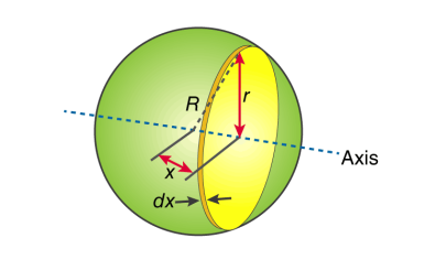
First, we take the moment of inertia of a disc that is thin. It is given as;
I = ½ MR2
In this case, we write it as;
DI (infinitesimally moment of inertia element) = ½ r2dm
Find the dm and dv using;
Dm = p dV
p = moment of a thin disk of mass dm
Dv = expressing mass dm in terms of density and volume
DV = π r2 dx
Now we replace dV into dm. We get;
Dm = p π r2 dx
And finally, we replace dm with dI.
DI = ½ p π r4 dx
The next step involves adding x to the equation. If we look at the diagram we see that r, R and x forms a triangle. Now we will use Pythagoras theorem which gives us;
r2 = R2 – x2
Now if we substitute the values we get;
DI = ½ p π (R2 – x2)2 dx
This leads to:
I = ½ p π -R∫R (R2 – x2)2 dx
After integration and expanding we get;
I = pπ 8/15 R5
Additionally, we have to find the density as well. For that we use;
P (density) = M (mass) / V (volume)
p = M (mass) / (4/3 πR3)
If we substitute all the values;
I = 8/15 π [M / (4/3 πR3)] R5
I = ⅖ MR2
Moment of inertia of Solid Cone
We will take a solid cone where its axis will pass through the centre with radius = r, height = h. We will need to determine the mass though.
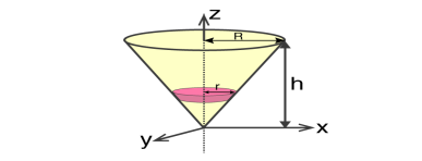
We take the elemental disc whose mass is given by;
Dm = ρ⋅ π r2dz
Density is given as;
ρ = M / V = M / (⅓π R2h)
With this, we will calculate the dm.
Dm = [M / (⅓π R2h)] X π r2dz
Dm = (3M / R2h) Xr2dz
If we consider the similarity of the triangle, then we have;
R / r = h / z
r = R .z / h
Now,
Dm = (3M / R2h )⋅( R2 / h2) ⋅ z2dz
Dm = (3M / h3 ). z2dz
If we consider z-axis, the moment of inertia of the elemental disk will be;
DI = ½ dmr2
DI = ½ ⋅(3M / h3) . z2 ⋅(z2 R2 / h2) dz
DI = 3 / 2 ⋅ M R2 / h5 X z4dz
Now we will follow the integration process. Here;
I = 3 / 2 ⋅ M R2 / h5 o∫h z4dz
I = 3 / 2 ⋅ M R2 / h5 [z5 / 5 ]oh
I = 3 / 2 ⋅ M R2 / h5 ⋅ h5 / 5
Therefore, I = 3/10 MR2
Q. Determine moment of Inertia for  section about x & y axis as shown in figure.
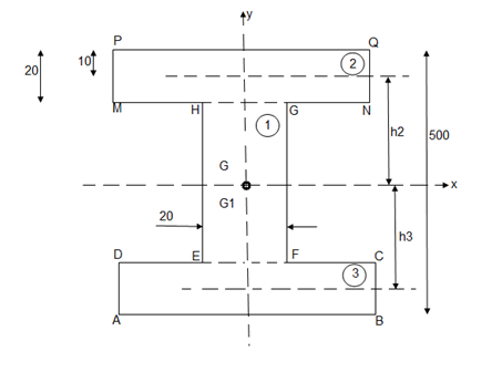
M.I. If this rectangle about xx and yy axis will be,         |     = 106666666.7 mm4 Consider rectangle ABCD area ③             = 213.64 
|
      |
Q: Determine the moment of inertia of shaded area as shown in figure about its centroid as axis.
Ans:
As this figure is symmetrical about
Y axis
X = 100 mm
Y = 
Where,
Area ① = rectangle
Area ② = triangle
Area ③ = circle

Y = 79.95 mm
 to find M.I. Of shaded portion , let G is the centroid of shaded area which is at y = 79.95 mm from base.
 of shaded portion @ x-x axis passing through its centroid G will be,
 x-x) +
 x-x) –
 x-x axis)
 1 +
1 +  2
2 3
3
= ( G1 + A1h12) +
  G2 + A2h22) -
  G3 + A3h32)
=  +
+  -60
-60 ] +
] +
 +
+  –
–


 84329013.21 mm4
 of shaded portion about y-y axis passing through its centroid G will be,
 y-y) +
 y-y axis) –
 y-yaxis)
 1 +
1 +  2
2 3
3
= 

= 80000000 + 16666666.67 – 3220623.34
 93446043.33 mm4
The Transfer theorem is also known as Parallel Axis Theorem.
When we calculated the area and mass moments of inertia via integration, one of the first things we had to do was to select a point or axis we were going to take the moment of inertia about. We then measured all distances from that point or axis, where the distances were the moment arms in our moment integrals. Because the centroid of a shape is the geometric center of an area or volume, the average distance to any one point in a body is at a minimum.
If we pick a different point or axis to take the moment of inertia about then on average all the distances in our moment integral will be a little bit bigger Specifically the further we move from the centroid, the larger the average distances become.
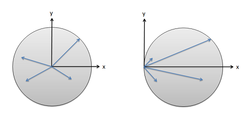
Fig: The distance used in our moment integrals depends on the point or axis chosen. These distances will be at a minimum at the centroid and will get larger as we start further from the centroid.
Though this complicates our analysis, the nice thing is that the change in the moment of inertia is predicable. It will always be at a minimum when we take the moment of inertia about the centroid, or an axis going through the centroid. This minimum, which we will call Ic is the value we will look up in our moment of inertia table. From this minimum, or unadjusted value, we can find the moment of inertia value about any point Ip by adding an an adjustment factor equal to the area times distance squared for area moments of inertia, or mass times distance squared for mass moments of inertia.
IxxP=IxxC+A∗r2
IxxP=IxxC+m∗r2
This adjustment process with the equations above is the parallel axis theorem. The area or mass terms simply represent the area or mass of the part you are looking at, while the distance (r) represents the distance we are moving the axis we are taking the moment of inertia about. This may be a vertical distance, a horizontal distance, or a diagonal depending on the axis the moment or inertia is about.
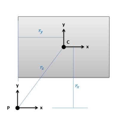
Fig: The distance (r) in the Parallel Axis Theorem represents the distance we are moving the axis we are taking the moment or intent about.
Say we are trying to find the moments of inertia of the rectangle above about point P. We would start by looking up Ixx, Iyy, and Jzz about the centroid of the rectangle (C) in the moment of inertia table. Then we would add on an area times distance squared term to each to find the adjusted moments of inertia about P. The distance we are moving the x axis for Ixx is the vertical distance rx, the distance we are moving the y axis for Iyy is the horizontal distance ry, and the distance we would move the z axis (which is pointing out of the page) for Jzz is the diagonal rz. Center of mass adjustments follow a similar logic, using mass times distance squared, where the distance represents how far you are moving the axis of rotation in three dimensional Spaces
Using the Method of Composite Parts to Find the Moment of Inertia
To find the moment of inertia of a body using the method of composite parts, you need to start by breaking your area or volume down into simple shapes. Make sure each individual shape is available in the moment of inertia table, and you can treat holes or cut-out’s as negative area or mass.
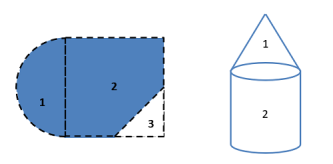
Fig: Start by breaking down your area or volume into simple parts and number those shapes. Holes or cut-outs will count as negative areas or masses.
Next you are going to create a table to keep track of values. Devote a row to each part that your numbered earlier, and include a final "total" row that will be used for some values. Most of the work of the method of composite parts is filling in this table The columns will vary slightly with what you are looking for, but you will generally need the following.
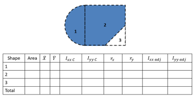
Most work in the method of composite parts will revolve around filling out a table such as this one. This table contains the rows and columns necessary to find the rectangular area moments of inertia (Ixx and Iyy) for this composite body.
- The area or mass for each piece (area for area moments of inertia or mass for mass moments of inertia). Remember cut outs should be listed as negative areas or masses.
- The centroid or center of mass locations (X, Y and possibly Z coordinates). Most of the time, we will be finding the moment of inertia about centroid of the composite shape, and if that is not explicitly given to you, you will need to find that before going further. For more details on this, see the page "Centroids and Center of Mass via Method of Composite Parts".
- The moment of inertia values about each shape's centroid. To find these values you will plug numbers for height, radius, mass, etc. into formulas on the moment of inertia table. Do not use these formulas blindly though as you may need to mentally rotate the body, and thus switch equations, if the orientation of the shape in the table does not match the orientation of the shape in your diagram.
- The adjustment distances (r) for each shape. For this value you will want to determine how far the x-axis, y-axis, or z-axis moves to go from the centroid of the piece to the overall centroid, or point you are taking the moment of inertia about. To calculate these values generally, you will be finding the horizontal, vertical, or diagonal distances between piece centroids and the overall centroids that you have listed earlier in the table. See the parallel axis theorem section of this page earlier for more details.
- Finally, you will have a column of the adjusted moments of inertia. Take the original moment of inertia about the centroid, then simply add your area times r squared term or mass times r squared term for this adjusted value.
The overall moment of inertia of your composite body is simply the sum of all of the adjusted moments of inertia for the pieces, which will be the sum of the values in the last column (or columns if you are finding the moments of inertia about more than one axis).
Product of inertia
In addition to the moment of inertia, the product of inertia is commonly used. Here only the product of the area is defined and discussed. The product of inertia defined as
Ixixj=∫AxixjdA
For example, the product of inertia for xx and yy axes is
Ixy=∫AxydA
Product of inertia can be positive or negative value as oppose the moment of inertia. The calculation of the product of inertia isn't different much for the calculation of the moment of inertia. The units of the product of inertia are the same as for moment of inertia.
Transfer of Axis Theorem
Same as for moment of inertia there is also similar theorem.
I x′y′ = ∫Ax′y′dA= ∫A(x+Δx)(y+Δy)dA
Expanding equation above results in
I x′y′ = ∫AxydA+ ∫AxΔydA+ ∫AΔxydA+ ∫AΔxΔydA
The final form is
I x′y′= Ixy+ ΔxΔydA
There are several relationships should be mentioned
I xy=I yx
Symmetrical area has zero product of inertia because integration of odd function (asymmmertial function) left part cancel the right part.
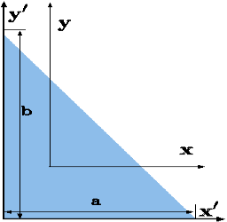
Fig. Product of inertia
Polar Moment of Inertia is a measure of an object’s capacity to oppose or resist torsion when some amount of torque is applied to it on a specified axis. Torsion, on the other hand, is nothing but the twisting of an object due to an applied torque. Polar moment of inertia basically describes the cylindrical object’s (including its segments) resistance to torsional deformation when torque is applied in a plane that is parallel to the cross-section area or in a plane that is perpendicular to the object’s central axis.
If we put it in simple terms polar moment of inertia is the resistance offered by a beam or shaft when it is being distorted by torsion. This opposition usually arises from the cross-sectional area and it should be noted that it does not depend on the material composition. If the polar moment of inertia is of higher magnitude then the torsional resistance of the object will also be greater. More torque will be required to turn the shaft at an angle.
Nonetheless, it is one of the main aspects of the area moment of inertia and we can use the perpendicular axis theorem to link the two quantities.
Polar Moment Of Inertia Formula
Polar Moment of Inertia is also called the second polar moment of area. It is usually denoted by IZ. However, sometimes J or JZ is also used. Polar Moment of Inertia can be represented mathematically with the given formula;
I or J = r2 dA
Here,
r = distance to the element dA.
Units
The dimension unit of polar moment of inertia is length to the power of four (L4); The SI unit of this property is, meters to the fourth power (m4). In the imperial unit system, it is inches to the fourth power (in4).
Types of Cross-section Polar Moment of Inertia
There are three main types of cross-section polar moment of inertia. They are as follows.

1. Hollow Shaft
To determine the polar moment of inertia we use;
Jhollow = π(R04–R14)/2
R1 and Ro = inner and outer radius of the hollow shaft.
2. Thin-Walled Shaft
To determine the polar moment of inertia we use;
Jthin = 2πt [R0+Ri/2]3
t = thickness of the thin-walled shaft.
3. Solid Circular Shaft
To determine the polar moment of inertia we use the following formula;
Jsolid = πR4/2
R = radius of the circular shaft.
Uses and Limitations
Generally, the second polar moment of area is used in determining the angular displacement of a body that is subjected to torque or to calculate the torsion force on a circular body. As for the limitation, the polar moment of inertia is not suitable for analysing shafts and beams with non-circular cross-sections. This is mainly because objects with non-circular cross-sections tend to warp when torque is applied and it further leads to out-of-plane deformations.
Shape | Area(a) | Moment of Inertia | Radius of gyration (r) | Polar moment of Inertia (J) |
Rectangle 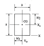 | A = bh | IXa = bh3/12 Iya = hb3/12 IX = bh3/3
| rx0 = h/12 ry0 = b/12 rx = h/3
| ICG = hb/12 (b2 + h2) |
Triangle 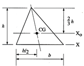 | A = bh/2 | IXa = bh3/36 IX = bh3/12
| rx0 = h/18 rx = h/6
|
|
Circle 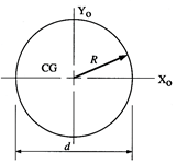 | A = πd2/4 = 0.7854 d2 | Ix0 = Iy0 = πd2/64 | Γx0 = Γy0 = d/4 | ICG = πd2/32 |
Semicircle 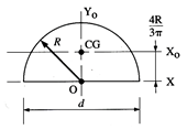 | A = πR2/4 = 1.571 R2 | Ix0 = 01098 R4 Iy0 = Ix = πR4/8 | Γx0 = 0.264 R Γy0 = Γx = R/2 | ICG = Ix0 + Iy0 = 0 I0 = πR4/4 |
Hollow circle 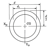 | A =  | Ix0 =  Iy0 = Ix0 | Γx0 =  Γy0 = Γx0 | ICG =  |
Hollow rectangle 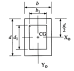 | A = bd – b1d1 | Ix0 =  Iy0 =  | Γx0 =  Γy0 =  | ICG = Ix0 + Iy0 |
Quarter circle 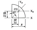 | A = πR2/4 | Ix0 = Iy0 = 0.05 Ix = πR4/16 | Γx0 = Γy0 = 0.2∈ rx = 0.5 R | ICG = 0.1098 R4 |
Principal moments of inertia and principal axes
For a general three-dimensional body, it is always possible to find 3 mutually orthogonal axis (an x, y, z coordinate system) for which the products of inertia are zero, and the inertia matrix takes a diagonal form. In most problems, this would be the preferred system in which to formulate a problem. For a rotation about only one of this axis, the angular momentum vector is parallel to the angular velocity vector. For symmetric bodies, it may be obvious which axis is principle axis. However, for an irregular-shaped body this coordinate system may be difficult to determine by inspection; we will present a general method to determine these axes in the next section. But, if the body has symmetries with respect to some of the axis, then some of the products of inertia become zero and we can identify the principal axes.
For instance, if the body is symmetric with respect to the plane x’ = 0 then, we will have Ix’y’ = Iy’z’ = Ix’z’ = Iz’x’ =0and x’ will be a principal axis. This can be shown by looking at the definition of the products of inertia.
The integral for, say,Ix’y’ can be decomposed into two integrals for the two halves of the body at either side of the plane x’ = 0. The integrand on one halfx’ y’ will be equal in magnitude and opposite in sign to the integrand on the other half (because x’ will change sign). Therefore, the integrals over the two halves will cancel each other and the product of inertia Ix’y’ will be zero. (As will the product of inertia Ix’z’) Also, if the body is symmetric with respect to two planes passing through the center of mass which are orthogonal to the coordinate axis, then the tensor of inertia is diagonal, with Ix’y’ = Ix’z’ = Iy’z’ = 0
Another case of practical importance is when we consider axisymmetric bodies of revolution. In this case, if one of the axis coincides with the axis of symmetry, the tensor of inertia has a simple diagonal form. For an axisymmetric body, the moments of inertia about the two axis in the plane will be equal. Therefore, the moment about any axis in this plane is equal to one of these. And therefore, any axis in the plane is a principal axis. One can extend this to show that if the moment of inertia is equal about two axis in the plane (IP P = Ixx), whether or not they are orthogonal, then all axes in the plane are principal axes and the moment of inertia is the same about all of them. In its inertial properties, the body behaves like a circular cylinder.
The tensor of inertia will take different forms when expressed in different axes. When the axes are such that the tensor of inertia is diagonal, then these axes are called the principal axes of inertia.
The Search for Principal Axes and Moments of Inertia as an Eigenvalue Problem
Three orthogonal principal axes of inertia always exist even though in bodies without symmetries their directions may not be obvious. To find the principle axis of a general body consider the body shown in the figure that rotates about an unknown principal axis. The total angular momentum vector is r in the direction of the principle axis. For rotation about the principal axis, the angular momentum and the angular velocity are in the same direction.
We seek a coordinate axes x, y and z, about which a rotation ωx, ωy and ωz, which is aligned with this coordinate direction, will be parallel to the angular momentum vector and related by the equation

We then express the general form for angular momentum vector in components along the x, y and z axis in term of the components of ω along these axes using the general form of the inertia tensor in the x, y, z system, we have

To obtain the special directions of that is aligned with a principal axis, we equate these two expressions.

At this point in the process we know the inertia tensor in an arbitrary x, y, and z system and are seeking the special orientation of ω which will align the angular momentum HG with the angular velocity ω. Collecting terms from equation(11) on the left-hand side, we obtain

Resulting in the requirement that

The structure of the solution for finding the principal axes of inertia and their magnitudes is a characteristic value problem. The three eigen values give the directions of the three principal axis, and the three eigenvectors give the moments of inertia with respect to each of these axis. In principal directions, the inertia tensor has the form

Where we will write Ix = Ixx, Iy = Iyy and Iz = Izz. Also, in principal axes we will then have
HG = Ixxi + Iyyj + Izzk
Q: A body of weight 50 N is along rough horizontal plane A pull of 18 N acting at an angle of 140 with the horizontal find coefficient of static friction.

Ans.
Considering the equilibrium of block

 18 Cos 14 – Fs = 0
 Fs = 17.46 N

RN + 18 Sin 14 – 50 = 0
RN = 45.64 N
As Fs =  S RN
S RN
17.46 =  S
S  45.64
45.64
 S = 0.386
Q: A block of mass m rests on frictional plane which makes an angle  with horizontal as shown if the coeff. Of friction between the block & frictional plane is 0.2, determine angle
  for limiting friction.
Ans:
For limiting friction
Tan  tan
tan  S =
S =  S
S
 tan-1
tan-1 S
S
 tan-1
tan-1
 11.310
Q: Determine whether the block shown is in equilibrium and find the magnitude and direction of friction force when  = 350 and P = 100 N
Ans.
Let us select inclined plane as x-x axis & perpendicular to plane as y-y axis
Let Fs = static frictional force which is required to maintain equilibrium.
 -------- resolving force along x-axis
 Fs + 100 Cos 35 – 250 Sin 35 = 0
 Fs – 61.48 = 0
 Fs = 61.48 N ----- frictional force
 -------- resolving force along y-axis
 -(250 Cos 35 + P Sin 35) + RN = 0
 -250 Cos 35 – 100 Sin 35 + RN = 0
-262.15 + RN = 0
 RN = 262.15 N -------- normal reaction
Maximum frictional force can be developed is given by
Fs max =  S
S RN = 0.3
  262.15
Fs max = 78.65 N
As frictional force required to maintain equilibrium (61.48 N) is less than max. Frictional force,
 Equilibrium will be maintained
Q. Uniform ladder AB has a length of 8 m and mass 24 kg end A is on horizontal floor and end B rests against vertical wall. A man of mass of 60 kg has to climb this ladder. At what position from the base, will be induce the slipping of ladder.
Ans.
Take  S = 0.34 at all contact surface.
Weight of man = 60 9.81 =588.6 N
Weight of ladder 
AB = 8 m
Impending motion
 Ac = 8 Cos 54
 BC = 8 Sin 54
 ɑ = 2.35 m
 b = x Cos 54
 FSA =
FSA =  S
S  RNA
RNA
 FSB =
FSB =  S
S  RNB
RNB
Considering the equilibrium of ladder
 FX = 0
             |
 

From eqn …..1
RNB = 0.34 

|
Taking moment about point A,
 MA = 0

 SB
SB Cos 54) – (RNB
 8 Sin 54) = 0
 (
( S
S  RNB
RNB  4.7) – (6.47 RNB) = 0
 1.598 RNB – 6.47 RNB = 0
 345.97x – 8.068 RNB = 553.284
 345.97x – 8.068
  251.14 = 553.284
 345.97x = 1472.913
X = 4.257 m
At X = 4.257 m from point A, along the ladder, man can climb without slipping.
Beyond this distance, ladder will be slipping.
Q. A 137 kg block is supported by a rope which Is wrapped 1.5 times around a horizontal Rod knowing that coeff. Of static friction Between rope and rod is 0.15, determine the range of values of P for which Equilibrium is maintained.
Ans.
Weight of block = 
Angle of contact = LAP Angle


A) Case I: when P > 1343.97 N
Force P tends to move the rope down ward and block moves upward. Thus the part rope on which force P is acting is height side and rope to which block is attached is slack side.
 =
=  =
= 
 P = 5525.34 N
B) Case II: when P < 1343.97 N
 force P is less than 1343.97 N, so block will move down ward & the side rope on which P acts will move upward.
 Rope side to which block is attached is tight side and another side is slack side.
 =
=  =
= 
 P = 326.92 N
 range of P for equilibrium is 326.92 N
Q. Two cylinders are connected by a rope that passes Over two fixed rods as shown. Knowing that the Coefficient of static friction between the rope and the rods is 0.40. Determine the range of the mass m of cylinder D for which equilibrium is maintained.
Ans.
Weight of cylinder = 50  9.81 = 490.5 N
Lap angle = 
 S = 0.40
A) Case I:
Weight of cylinder A > weight of cylinder B.
In this case cylinder A will tends to move downward while B will tends to move upward
Consider part AB of the Rope as AB rope is moving down,
Tension in hight side T1 = 
Tension in slack side = T2 = unknown.
 =
=  =
=  = 1.874
 = T2
= T2
 T2 = 261.74 N
Consider part CD, of the rope. As rope CD is moving upward,
Tension in tight side T1 = T2 of rope AB
Tension in tight side, T1 = 261.74 N
Tension in slack side = T2 = (m  9.81)
9.81)
    |   |
B) Case II:
Weight of cylinder A < weight of cylinder B
In this case cylinder a will tends to move upward while cylinder B will tends to move downward
Consider part AB of the rope moving upwards
Tension in slack side = side A = 
    |   |
Consider part CD of rope, Rope CD is moving downwards
Tension in tight side = T1 = (m 9.81) N
Tension in slack side = T2 = T1 of rope AB = 919.197 N
    |   |
Range of mass m for equilibrium to be maintained is
14.23 kg  m
m 175.59 kg
Q. A Force P = mg/6 is required to lower the cylinder with card making 1.25 turns around the fixed shaft. Determine the coeff. Of friction “ S” between the card and the shaft
Ans.
Refer the figure
Lap angle

= 2.5 radians
For flat belt,
 =
= 
 =
= 
 6
6 
 1.79 =
  S
S 2.5
2.5
 S = 0.23
Q. Determine the range of P for the equilibrium of block of weight W as shown in fig. The coeff. Of friction between rope and pulley is 0.2
Ans.
Case I: when P is max.
 =
= 
 =
= 
 Pmax = 1.369 w
Case II: when P is min.
 =
= 

 Pmin = 0.73 w
For equilibrium P must be between 0.73  P
P  1.369 w
Mohr's Circle for Mom. Of Inertia
- When all possible moments and products of inertia for a shape are plotted on a graph, the resulting graph is a circle.
- This graph makes it easy to find any moment or product of inertia for a shape that we want. All we have to do is use the geometrical properties of a circle.
- Ix and ly are plotted on horizontal axis
- Ixy is plotted on vertical axis
- Plot point 'X 1st (Ix, lxy)
- 'Y' will be on opposite side as (Iy, -lxy) (note signs of lxy)
- Now you have two points
- Draw the circle through these points
- Find any other points you need (usually Imin and Imax)
Finding Imin and Imax
- Once the circle is drawn (see previous slide) locate the center point (shown here as O)
- Form a right triangle by dropping a vertical line from point X to horizontal axis.
- Use this triangle to find the radius of the circle (hypotenuse) and the angle shown as 2
- Imin and Imax are simply the center plus or minus the radius.
Finding Theta
- It can be important to know the orientation (with respect to the x-y axis system) of a physical object for a given moment of inertia.
- Rotating the object's coordinate system through any angle will correspond to an angle of 2 on Mohr's Circle.
- Theta () is always measured:
- the same rotational direction on both the object and the graph.
- from point X on the graph and from the x-axis on the object.
The principle of virtual work was proposed by the Swiss mathematician Jean Bernoulli in the eighteenth century. It provides an alternative method for solving problems involving the equilibrium of a particle, a rigid body, or a system of connected rigid bodies.
The definitions of the work of a force and a couple can be presented in terms of the actual movements which are expressed by differential displacements having values of  and
and  . Consider now an imaginary or virtual movement of a body in static equilibrium, which indicates a displacement or rotation that is assumed and does not actually exist. These movements are first-order differential quantities and will be denoted by the symbols
  and
and  (delta r and delta
  ), respectively. The virtual work done by a force having a virtual displacement
  is
is

Similarly, when a couple undergoes a virtual rotation  in the plane of the couple forces, the virtual work is

According to the principle of virtual work if a body is in equilibrium, then virtual displacement of the body is zero for all the algebraic sum of the virtual work which is done by all the forces and moments of couple that are acting on the body. Thus,

For example, consider the free-body diagram of the particle (ball) that rests on the floor, Fig. Below. If we “imagine” the ball to be displaced downwards a virtual amount  then the weight does positive virtual work
  , and the normal force does negative virtual work
  , For equilibrium the total virtual work must be zero, so that

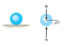
As seen from the above example, no added advantage is gained by solving particle and rigid-body equilibrium problems using the principle of virtual work. This is because for each application of the virtual-work equation, the virtual displacement, common to every term, factors out, leaving an equation that could have been obtained in a more direct manner by simply applying an equation of equilibrium.
A particle of mass m is acted upon by a number of forces f1,f2….fN. Suppose the particle undergoes a virtual displacement δu to reiterate, these impressed forces fido not cause the particle to move, one imagines it to be incorrectly positioned a little away from the true equilibrium position.
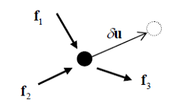
If the particle is moving with an acceleration a, the quantity -ma is treated as an inertial force. The total virtual work is then (each term here is the dot product of two vectors)
δW = (
Now if the particle is in equilibrium by the action of the effective (impressed plus inertial) force then δW = 0
This can be expressed as follows:
The principle of virtual work (or principle of virtual displacements) if a particle is in equilibrium under the action of a number of forces (including the inertial force) the total work done by the forces for a virtual displacement is zero.
Alternatively, one can define the external virtual work δWest =  , Wext and the virtual kinetic energy δK = ma. δu in which case the principle takes the form δWest = δK (compare with the work-energy principle
In the above, the principle of virtual work was derived using Newton’s second law. One could just as well regard the principle of virtual work as the fundamental principle and from it derive the conditions for equilibrium. In this case one can say that the principle of virtual work (or principle of virtual displacements)
a particle is in equilibrium under the action of a system of forces (including the inertial force) if the total work done by the forces is zero for any virtual displacement of the particle. The term kinematically admissible displacement is used to mean one that does not violate the constraints, and hence one arrives at the version of the principle which is often used in practice:
The principle of virtual work (or principle of virtual displacements):a particle is in equilibrium under the action of a system of forces (including the inertial force) if the total work done by the forces (excluding reaction forces) is zero for any kinematic ally admissible virtual displacement of the particle.
Key takeaways
1) The virtual work done by a force having a virtual displacement  is
is

Beam:
It is horizontal structural member on which different types of loads can be supported. It takes load from floor or roof & transfers to column.
The beam may be sometimes constructed in the inclined position for architectural point of view.
Types of Beam
- Simply supported beam –
A beam which is just resting on the supports at the end without any connection is known as simply supported beam. It is generally used for vertical landing system.

2. Overhanging Beam –
A beam which is supported at the intermediate point other than ends is called as overhanging beam. Here portion of beam is extended beyond the support

a) (singly overhanging beam)

b) (doubly overhanging beam)
3. Cantilever Beam –
A beam which is fixed at one end is called as cantilever beam

Here, there are three reactions components:
- Vertical reaction at A (RVA)
- Horizontal reaction at A (RHA)
- Fixing moment at A (MA)
We can assume any direction for above components.
4. Continuous Beam:
A beam having more than two support is called as continuous beam.

5. Compound Beam:
When two or more beams are joined together by using internal hinge; or when one beam rests over another beam by using internal roller, then such beam is called as compound beam.

Trusses are simply defined as triangulation of members to make the stabilized structure. Triangulation is the stable configuration mathematically. Generally, a truss has the members called as top chord, bottom chord, vertical chord and diagonal chord. The main functions of the trusses are:
- Carrying the loads from the over structures
- Providing adequate lateral stability to the entire structure
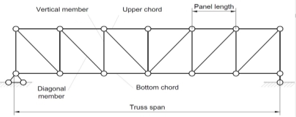
There are some basic assumptions in the designing process. It should be clarified that the construction of the trusses should conform with the design assumptions to avoid the unwanted failures due to the dispersion of the forces and loads.
Following are the assumptions in truss design.
- Truss members will carry only the axial forces
- The nodes i.e. the connections of the members are designed as pinned joints so that moments won’t be transferred to the members of the truss
- All the external loads and the reactions are act only on the nodes
- Generally, the truss should be in a plane.
- Typically the members of the trusses are made as I sections, angles, T sections, Tube sections, Square sections and channel sections. I sections are more preferable as an optimized section in terms of the structural forces.
Types of Trusses
- Simple truss – indicates a single triangular truss. These trusses are most often used as the roof trusses.
- Planar truss – as the name implies it is a two-dimensional truss. If all the members and the nodes are in a planar surface, then this truss is a planar truss.
- Space frame truss – Contrast to planar truss, the members and the nodes are located in the three-dimensional space. Electrical and telecom towers are the one of the simplest examples that we are seeing in the day-to-day life.
Simple Truss: It is possible to create a simple truss by joining three bars together to form a triangle. We can increase the size of the truss by adding two more members with an additional joint. By repeating this process, we can develop simple trusses with different shapes as shown below. The triangular building block assures internal stability of the truss structure as it is increased in size.

Although it is possible to have non-triangular cells in a simple truss, internal stability will not be guaranteed in that case.
Compound Truss: A compound truss is made up of simple trusses joined together to form a larger truss. The figure below shows a compound truss consisting of two simple trusses joined by a common joint and a bar. It is also possible to have multiple simple trusses joined together to create a larger compound truss. The connection of simple trusses then becomes a design issue determined based on the size of the resulting compound truss. Compound trusses are commonly used to support loads over long spans as in bridges.
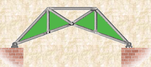
Complex Truss: A complex truss uses a general layout of members different from that used in simple and compound trusses. It often incorporates overlapping members.
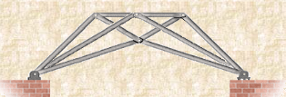
Key takeaways
1) Simple truss – indicates a single triangular truss. These trusses are most often used as the roof trusses.
2) Planar truss – as the name implies it is a two dimensional truss. If all the members and the nodes are in a planar surface, then this truss is a planar truss
References:
1. Engineering Mechanics: F. L. Singer
2. Engineering Mechanics: Timoshenko & Young
3. Engineering Mechanics: Bear & Johnston
4. Engineering Mechanics: I. H. Shames
5. Engineering Mechanics: A. Nelson