Unit - 5
Quality of services
QoS is an overall performance measure of the computer network. Quality of Service (QoS) is a group of technologies that work together on a network to ensure that high-priority applications and traffic are reliably delivered even when network capacity is reduced. This is accomplished using QoS technologies, which provide differential handling and power allocation of individual network traffic flows.
Multimedia applications that combine audio, video, and data should be supported by the network. It should be able to do so with enough bandwidth. The delivery timeliness can be extremely critical. Real-time apps are applications that are responsive to data timeliness. The information should be provided in a timely manner. Help quality of service refers to a network that can deliver these various levels of service.
Bandwidth (throughput), latency (delay), jitter (variance in latency), and error rate are all important QoS metrics. As a result, QoS is especially important for high-bandwidth, real-time traffic like VoIP, video conferencing, and video-on-demand, which are sensitive to latency and jitter.
Important flow characteristics of the QoS are given below:
1. Reliability
If a packet gets lost or acknowledgement is not received (at sender), the re-transmission of data will be needed. This decreases the reliability.
The importance of reliability can differ according to the application.
Example: E- mail and file transfer need to have a reliable transmission as compared to that of an audio conferencing.
2. Delay
Delay of a message from source to destination is a very important characteristic. However, delay can be tolerated differently by the different applications.
Example: The time delay cannot be tolerated in audio conferencing (needs a minimum time delay), while the time delay in the email or file transfer has less importance.
3. Jitter
The jitter is the variation in the packet delay.
If the difference between delays is large, then it is called a high jitter. On the contrary, if the difference between delays is small, it is known as low jitter.
Example:
Case1: If 3 packets are sent at times 0, 1, 2 and received at 10, 11, 12. Here, the delay is the same for all packets and it is acceptable for the telephonic conversation.
Case2: If 3 packets 0, 1, 2 are sent and received at 31, 34, 39, so the delay is different for all packets. In this case, the time delay is not acceptable for the telephonic conversation.
4. Bandwidth
Different applications need different bandwidth.
Example: Video conferencing needs more bandwidth in comparison to that of sending an e-mail.
Integrated Services and Differentiated Service
These two models are designed to provide Quality of Service (QoS) in the network.
1. Integrated Services (IntServ)
Integrated service is a flow-based QoS model and designed for IP.
In integrated services, a user needs to create a flow in the network, from source to destination and needs to inform all routers (every router in the system implements IntServ) of the resource requirement.
Following are the steps to understand how integrated services work.
i) Resource Reservation Protocol (RSVP)
An IP is connectionless, datagram, packet-switching protocol. To implement a flow-based model, a signaling protocol is used to run over IP, which provides the signaling mechanism to make reservations (every application needs assurance to make reservation), this protocol is called RSVP.
Ii) Flow Specification
While making reservations, resources need to define the flow specification. The flow specification has two parts:
a) Resource specification
It defines the resources that the flow needs to reserve. For example: Buffer, bandwidth, etc.
b) Traffic specification
It defines the traffic categorization of the flow.
Iii) Admit or deny
After receiving the flow specification from an application, the router decides to admit or deny the service and the decision can be taken based on the previous commitments of the router and current availability of the resource.
Classification of services
The two classes of services to define Integrated Services are:
a) Guaranteed Service Class
This service guarantees that the packets arrive within a specific delivery time and not discarded, if the traffic flow maintains the traffic specification boundary.
This type of service is designed for real time traffic, which needs a guaranty of minimum end to end delay.
Example: Audio conferencing.
b) Controlled Load Service Class
This type of service is designed for the applications, which can accept some delays, but are sensitive to overload networks and to the possibility of losing packets.
Example: E-mail or file transfer.
Problems with Integrated Services
The two problems with the Integrated services are:
i) Scalability
In Integrated Services, it is necessary for each router to keep information of each flow. But this is not always possible due to the growing network.
Ii) Service- Type Limitation
The integrated services model provides only two types of services, guaranteed and control-load.
2. Differentiated Services (DS or Diffserv):
● DS is a computer networking model, which is designed to achieve scalability by managing the network traffic.
● DS is a class based QoS model specially designed for IP.
● DS was designed by IETF (Internet Engineering Task Force) to handle the problems of Integrated Services.
The solutions to handle the problems of Integrated Services are explained below:
1. Scalability
The main processing unit can be moved from the central place to the edge of the network to achieve scalability. The router does not need to store the information about the flows and the applications (or the hosts) define the type of services they want every time while sending the packets.
2. Service Type Limitation
The routers, route the packets on the basis of the class of services defined in the packet and not by the flow. This method is applied by defining the classes based on the requirement of the applications.
Key takeaway:
● QoS is an overall performance measure of the computer network.
● Bandwidth (throughput), latency (delay), jitter (variance in latency), and error rate are all important QoS metrics.
● QoS is especially important for high-bandwidth, real-time traffic like VoIP, video conferencing, and video-on-demand, which are sensitive to latency and jitter.
Let's have a look at how the Leaky Bucket Algorithm works.
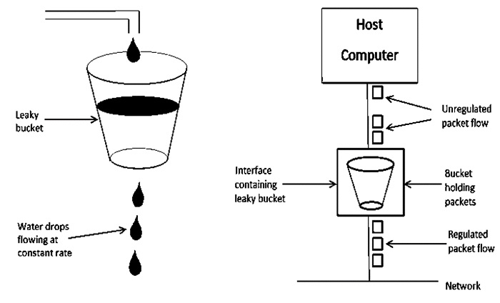
Fig 1: Leaky bucket algorithm
The Leaky Bucket Algorithm is primarily responsible for controlling the total volume and rate of traffic supplied to the network.
Step 1: Consider a bucket with a small hole at the bottom into which water is poured at a variable pace, but which leaks at a constant rate.
Step 2 So (as long as there is water in the bucket), the rate at which water leaks is unaffected by the pace at which water is poured into the bucket.
Step 3: If the bucket is full, any more water that enters will pour over the edges and be lost.
Step 4: The same technique was applied to network packets. Consider the fact that data is arriving at varying speeds from the source. Assume a source transmits data at 10 Mbps for 4 seconds. For the next three seconds, there is no data. For 2 seconds, the source transfers data at an 8 Mbps pace. Thus, 68 Mb of data was sent in less than 8 seconds.
As a result, if you employ a leaky bucket technique, the data flow will be 8 Mbps for 9 seconds. As a result, the steady flow is maintained.
One of the strategies for congestion management algorithms is the token bucket algorithm. When there are too many packets in the network, it causes packet delay and packet loss, lowering the system's performance. Congestion is the term for this circumstance.
Congestion management is shared between the network layer and the transport layer. Trying to lessen the burden that the transport layer places on the network is one of the most effective strategies to control congestion. To keep this network running, the network and transport layers must collaborate.
The Token Bucket Algorithm is illustrated graphically as follows:
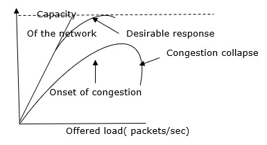
When there is too much traffic, performance suffers significantly.
Token Bucket Algorithm
No matter how busy the network is, the leaky bucket algorithm enforces output patterns at the average rate. To deal with the increased traffic, we'll need a flexible algorithm that won't lose data. The token bucket algorithm is one such method.
Let's take a look at this method one step at a time, as shown below.
Step 1: Tokens are thrown into the bucket f at regular intervals.
Step 2: The bucket can hold a maximum of f.
Step 3: If the packet is ready, a token from the bucket is taken, and the packet is sent.
Step 4 Assume that the packet cannot be forwarded if there is no token in the bucket.
Example
Let's look at an example of the Token Bucket Algorithm.
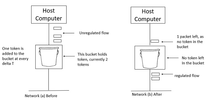
Two tokens are in the bucket in figure (a), and three packets are waiting to be transmitted out of the interface.
Figure (b) shows that two packets have been sent out after two tokens have been consumed, and one packet remains.
The token bucket method is less limiting than the Leaky bucket algorithm, allowing for more traffic. The amount of tokens accessible in the bucket at any given time determines the maximum amount of bustle.
The token bucket technique is simple to construct because the tokens are counted using a variable. The counter is incremented every t seconds and then decremented whenever a packet is sent. When the counter reaches zero, no further packet is sent out.
This is shown in below given diagram −
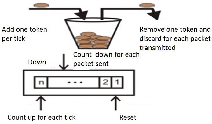
Some advantage of token Bucket over leaky bucket –
● If the token bucket is full, tokens are discarded rather than packets. Packets are discarded while in a leaky bucket.
● Token Bucket may deliver large bursts at a quicker pace, but a leaky bucket sends packets at the same rate every time.
Difference between leaky bucket and token bucket
Leaky Bucket | Token Bucket |
When the host has to send a packet , packet is thrown in bucket. | In this leaky bucket holds tokens generated at regular intervals of time. |
Bucket leaks at constant rate | Bucket has maximum capacity. |
Bursty traffic is converted into uniform traffic by leaky bucket. | If there is a ready packet , a token is removed from Bucket and packet is send. |
In practice bucket is a finite queue outputs at finite rate | If there is a no token in bucket, packet can not be send.
|
The Domain Name System (DNS) is a hierarchical decentralized naming system for computers, services, or other resources connected to the Internet or a private network. It associates various information with domain names assigned to each of the participating entities.
Currently, the limit on domain name length is 63 characters, including www. And .com or other extensions. Domain names are also restricted to only a subset of ASCII characters, making many other languages unable to properly represent their names and words. Punycode-based IDNA systems, which map Unicode strings to valid DNS character sets, have been validated and adopted by some registries as a workaround.
A protocol that can be used on various platforms is DNS. The domain name space (tree) is split into three separate parts on the Internet: generic domains, country domains, and the inverse domain.
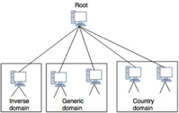
Fig 2: DNS in internet
Generic Domains
Based on their generic behavior, the generic domains identify registered hosts. A domain, which is an index to the domain name space database, is specified by each node in the tree.
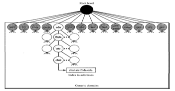
Fig 3: Generic domain
Looking at the tree, we see that 14 possible labels are allowed by the first level in the generic domains segment.
Label |
Description |
Aero |
Airlines and aerospace companies |
Biz |
Business or firms |
Com |
Commercial organizations |
Coop |
Cooperative business organization |
Edu |
Educational institutions |
Gov |
Government institutions |
Info |
Information service provider |
Int |
International organizations |
Mil |
Military groups |
Museum |
Museum and other nonprofit organization |
Name |
Personal name |
Net |
Network support centers |
Org |
Nonprofit organizations |
Pro |
Professional individual organizations |
Country Domains
The segment on country domains utilizes two-character country abbreviations (e.g., us for United States). The second labels may be organizational, or national designations may be more precise.
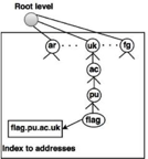
Fig 4: Country domain
For instance, the country domain is "au" for Australia, India is .in, and the UK is .uk
Inverse domains
For mapping an address to a name, the inverse domain is used. This can happen when a server has received a request from a client to do a task for testing. Although the server has a file containing a list of approved clients, only the client's IP address (extracted from the IP packet received) is identified. The server prompts its resolver to send a question to the DNS server to map a name to an address to decide if the client is on the approved list.
A reverse or pointer (PTR) query is called this type of query. The inverse domain is added to the domain name space with a first-level node named arpa to handle a pointer query (for historical reasons). One single node called in-addr is also the second stage (for inverse address). IP addresses are specified in the rest of the domain.
Also, the servers managing the inverse domain are hierarchical.
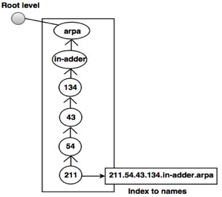
Fig 5: Inverse domain
For example, when a client sends a request to a server to perform a specific task, the server finds an approved client list. The list includes only the client's IP addresses.
Key takeaway:
- DNS is a directory service that maps a host's name to its numerical address on a network.
- DNS is necessary for the internet to work.
- Based on their generic behavior, the generic domains identify registered hosts.
- The segment on country domains utilizes two-character country abbreviations.
- For mapping an address to a name, the inverse domain is used.
- The servers managing the inverse domain are hierarchical.
Network management is an important part of running a successful network. Network administrators require software to keep track of the network devices' capabilities, as well as the interactions between them and the services they provide. SNMP has become the de facto standard for network management solutions, and it is closely linked to remote monitoring (RMON) and Management Information Bases (MIBs) (MIB).
Each controlled device in the network has a set of variables that describe its current state. You can read the values of these variables to track managed devices, and you can write values into these variables to manipulate managed devices.
Network Management Architecture
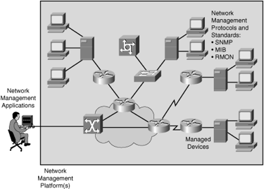
Fig 6: Network management architecture
The following components make up the network management architecture:
● A network management system (NMS) is a computer system that runs programs to track and control controlled devices. The majority of the processing and memory resources needed for network management are provided by NMSs.
● SNMP, MIB, and RMON are examples of network management protocols that allow the sharing of management information between the NMS and managed devices.
● A computer (such as a router) that is operated by an NMS is referred to as a managed device.
● Management agents, such as SNMP agents and RMON agents, are software that gathers and stores management information on controlled devices.
● Management information: Data that is relevant to the management of a system and is typically stored in MIBs.
A network management system can run a number of network management applications, depending on the network platform (such as the hardware or operating system). Management information is stored on network computers, with management agents collecting and storing data in a standardized data definition system known as the MIB.
The data collected by the management agents is retrieved by the network management program using SNMP or other network management protocols. The retrieved data is usually processed and prepared for display with a GUI, which allows the user to monitor controlled devices and program the network management framework using a graphical representation of the network.
Key takeaway:
- Network management is an important part of running a successful network.
- SNMP is the simplest network management protocol.
- A network management system can run a number of network management applications, depending on the network platform (such as the hardware or operating system).
The idea is to use the Internet, with some added capabilities, as a telephone network. This programme allows contact between two parties over the packet-switched Internet, instead of communicating over a circuit-switched network.
Two protocols were developed to deal with this kind of Communication:
SIP(Session Initiation Protocol) and H.323
Session Initiation Protocol (SIP)
The Session Initiation Protocol (SIP) is an application layer protocol established by IETE that creates, manages and terminates a multimedia session (call). Two-party, multiparty, or multicast sessions can be generated using it.
SIP is built to be independent of the underlying transport layer; UDP, TCP, or SCTP may be used.
Message:
SIP is a protocol based on text, and so is HTTP. SIP uses messages, as does HTTP. There are six specified messages.
There is a header and a body in each post. The header consists of several lines which describe the message structure, the capacity of the caller, media type, and so on.

Fig 7: SIP message
● A session with the INVITE message is initialised by the caller.
● The caller sends an ACK message for clarification after the caller answers the call.
● A session is terminated by a BYE call.
● The OPTIONS message asks about the capabilities of a computer.
● The CANCEL message cancels an initialization process which has already begun.
● When the callee is not available, the REGISTER message allows a connection.
Address
A telephone number identifies the sender in a periodic telephone correspondence, and another telephone number identifies the recipient. SIP is very versatile. To distinguish the sender and recipient, an e-mail address, an IP address, a telephone number, and other types of addresses may be used in SIP. The address needs to be in SIP format, though (also called scheme).

Fig 8: SIP address format
Simple sessions
Three modules consist of a basic session using SIP: Establish, Communicating, and terminating.
● Establish a session: It takes a three-way handshake to create a session in SIP. Using UDP, TCP, or SCTP to start contact, the caller sends an INVITE request. She sends a response message if the caller is ready to start the session.
● Communicating: The caller and the callee will communicate by using two temporary ports after the session has been created.
● Terminating the session: With a BYE message sent by either side, the session can be terminated.
Tracking the callee
What happens if there isn't a callee sitting in her terminal? She might be away or at another terminal from her system. If DHCP is being used, she does not even have a set IP address. SIP has a function that seeks the IP address of the terminal at which the callee is sitting (similar to one in DNS). SIP uses the idea of registration to do this monitoring. Some servers are specified by SIP as registrars. A user is registered with at least one registrar server at any time; that server knows the callee's IP address.
The caller should use the e-mail address rather than the IP address in the INVITE message when a caller wants to connect with the caller. The message goes to a server that is a proxy. The proxy server sends a search message (not part of the SIP) to the server of the registrar that registered the call. The proxy server takes the caller's INVITE message and adds the newly discovered IP address of the caller when the proxy server receives a reply message from the registrar's server. This message is sent to the callee, then.
H.323
H.323 is a standard developed by lTV to allow computers (called terminals in H.323) linked to the Internet to communicate to telephones on the public telephone network.
A gateway links the telephone network to the Internet. A gateway is typically a five-layer interface that can convert a message from one stack of protocols to another. The gateway does the very same thing here. It converts a message from the telephone network into an Internet message. As we mentioned in SIP, the gatekeeper server on the local area network plays the role of the registrar server.
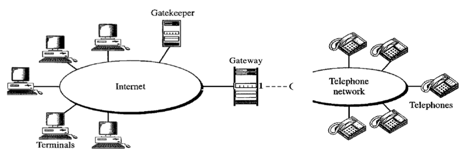
Fig 9: Architecture of H.323
Key takeaway:
● This programme allows contact between two parties over the packet-switched Internet, instead of communicating over a circuit-switched network.
● The Session Initiation Protocol is an application layer protocol established by IETE.
● SIP uses messages, as does HTTP.
● The address needs to be in SIP format.
● The proxy server sends a search message to the server of the registrar that registered the call.
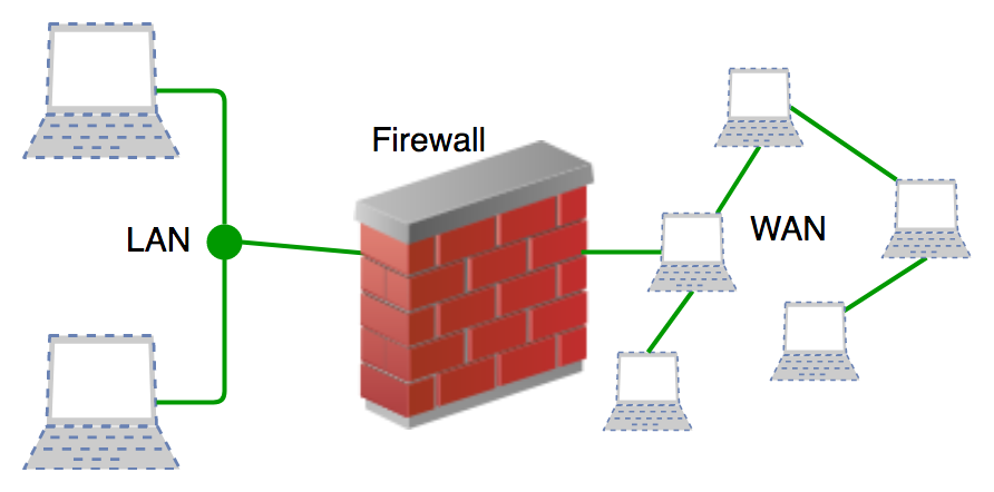
A firewall is a sort of network security hardware or software application that monitors and filters incoming and outgoing network traffic according to a set of security rules. It serves as a firewall between internal private networks and public networks (such as the public Internet).
A firewall's principal goal is to allow non-threatening communication while blocking dangerous or undesirable data transmission in order to protect the computer from viruses and attacks. A firewall is a cybersecurity solution that filters network traffic and assists users in preventing harmful malware from gaining access to the Internet on compromised machines.
A firewall creates a barrier between safe internal networks and untrusted external networks like the Internet.
History and needs for firewall
Prior to firewalls, network security was handled through router-based Access Control Lists (ACLs). ACLs are rules that define whether a specific IP address should have network access granted or refused.
ACLs, on the other hand, have no way of knowing what kind of packet they're preventing. Furthermore, ACL alone is insufficient to keep threats out of the network. As a result, the Firewall was created.
Organizations can no longer afford to be without Internet access. Accessing the Internet, on the other hand, promotes the business because it allows the outside world to connect with the organization's internal network. This puts the organisation in jeopardy. A Firewall is required to protect the internal network from illegal traffic.
Why a firewall?
Firewalls are used to protect against malware and network-based threats. They can also aid in the prevention of application-layer assaults. These firewalls serve as a barrier or a gatekeeper. They keep track of every connection our machine makes to another network. They only let data packets to pass through them if the data is coming or going from a trusted source designated by the user.
Firewalls are built in such a way that they can identify and counter-attack threats throughout the network fast. They can work with regulations that have been set up to defend the network, as well as conduct fast inspections to look for any unusual activity. In other words, the firewall can be used as a traffic controller.
Types of firewall
There are two types of firewalls: host-based and network-based.
● Host- based Firewalls: Each network node has a host-based firewall that controls all incoming and outgoing packets. It is a software programme or set of programmes that is included with the operating system. Because network firewalls cannot provide protection inside a trusted network, host-based firewalls are required. Each host is protected by a host firewall from assaults and illegal access.
● Network-based Firewalls: On the network level, there is a network firewall function. In other words, these firewalls filter all network traffic, including incoming and outgoing. It protects the internal network by filtering traffic according to firewall rules. There could be two or more network interface cards in a network firewall (NICs). A specialized system with proprietary software is frequently used as a network-based firewall.
Limitations
Firewalls have a number of limitations, including the following:
● Customers can still visit harmful websites across firewalls, exposing them open to internal risks and attacks.
● Firewalls are powerless to prevent the transmission of virus-infected files or software.
● Passwords can't be protected by firewalls.
● If security rules are misconfigured, firewalls will not be able to protect you.
● Non-technical security vulnerabilities, such as social engineering, are not protected by firewalls.
References:
- Peterson and Davie, “Computer Networks: A Systems Approach”, Morgan Kaufmann
- W. A. Shay, “Understanding Communications and Networks”, Cengage Learning.
- D. Comer, “Computer Networks and Internets”, Pearson.
- Behrouz Forouzan, “TCP/IP Protocol Suite”, McGraw Hill.