Unit - 2
Assembler
1. Compilers and Assemblers
- AN program or that of a compiler is simply another program that may execute on your ADPS.
- The sole issue special that of AN program or that of a compiler is that it interprets programs from that of the one type (source code) to a different (machine code).
- A typical that of the x86 program, as an example, would browse that of the lines of text with that of the x86 directions, take apart every of that of the statement, so write the binary equivalent of every of that of the instruction on to memory or thereto that of a file for later execution.
- Assemblers have 2 massive blessings over committal to writing in machine code:
- First, they mechanically translate strings like
- Add ax, bx
- Mov ax, [1000h]
To their corresponding binary type.
- Second, and doubtless even that of the additional necessary, assemblers allow you to attach labels to that of the statements so consult with them in this of a jump directions
(A coder won't ought to recognize the target address of AN instruction once specifying targets of jump directions.)
2. The Assembly method
1. Aggregation the ASCII text file into that of AN object file
2. Linking the article file thereupon of the opposite modules or the libraries into AN workable program
3. Loading the program into memory
4. Running the program
3. Tiny Assembly Sample
; add_16_bytes.asm
;
.586P
; Flat memory model, normal career convention:
.MODEL FLAT, STDCALL
;
; knowledge section
_DATA section
Values sound unit sixteen DUP( five ) ; 16 bytes of values "5"
_DATA ENDS
; Code section
_TEXT section
START:
Mov eax, zero ; clear result
Mov bl, sixteen ; init loop counter
Lea esi, values ; init knowledge pointer
Addup:
Add al, [esi] ; add computer memory unit to add
INC esi ; increment knowledge pointer
Dec bl ; decrement loop counter
Jnz addup ; if BL not zero, continue
Mov [esi], al ; save add
Dowse ; Exit
_TEXT ENDS
END START
- Listing file: add_16_bytes.lst
4. MASM statement Interface
- To assemble which of the run AN program program named myprog.asm, sort the subsequent commands:
- Decision "C:\Program Files\Microsoft Visual Studio 8\Common7\Tools\vsvars32.bat"
- Cubic centimetre /coff /c /Fl myprog.asm
- LINK /debug /subsystem:console /entry:start /out:myprog.exe myprog.obj ..\iolib\io.obj kernel32.lib
- Myprog.exe
5. Assembling
- At assembly time, the assembler:
o Evaluates conditional-assembly directives, aggregation if the conditions are true.
o Expands macros and that of the macro functions.
o Evaluates constant expressions like MYFLAG AND 80H, subbing the calculated worth for the expression.
o Encodes directions and non address operands. As an example, mov cx, 13; are often encoded at assembly time as a result of the instruction doesn't access memory.
o Saves memory offsets as that of the offsets from their segments.
o Places sections and segment attributes within the object file.
o Saves placeholders for that of the offsets and that of the segments (relocatable addresses).
o Outputs an inventory if requested.
o Passes messages (such as INCLUDELIB) on to the linker.
6. Linking
- Once your ASCII text file is assembled thereto of the ensuing object file is passed to that of the linker. At this time, the linker is also mix many object files into that of AN workable program. The linker:
o Combines segments in keeping with the directions within the object files, rearranging the positions of segments that share constant category or cluster.
o Fills in placeholders for offsets (relocatable addresses).
o Writes relocations for segments into the header of .EXE files (but not .COM files).
o Writes the result as AN workable program file.
7. Loading
- When loading that of the workable file into the memory, the in that of the operation system:
o Creates that of the program section prefix (PSP) header in that of the memory.
o Allocates memory for that of the program, supported the values within that of the PSP.
o Masses the program.
o Calculates the right values for absolute addresses from the relocation table.
o Masses the section registers SS, CS, DS, and Es with values that time to the correct areas of memory.
8. Helpful Tools and Utilities
- DUMPBIN dismantlement program
- Debuggers: OllyDbg and WinDbg
- Consol I/O: iolib.
Label
Symbolic labeling of an assembler address (command address at Machine level)
Mnemomic
Symbolic description of an operation
Operands
Contains of variables or addressee if necessary
Comments
Optional field
Statement format An Assembly language statement has following format:
[Label] <opcode> <operand spec>[,<operand spec>..]
If a label is specified in a statement, it is associated as a symbolic name with the memory word generated for the statement.
<operand spec> has the following syntax:
<symbolic name> [+<displacement>] [(<index register>)]
Eg. AREA, AREA+5, AREA(4), AREA+5(4)
AREA – memory word with which name AREA is associated
AREA +5 : The memory word, which is 5 words away from the word which name is AREA, here ’5’ is displacement offset from AREA
AREA(4) : indexing with index register 4 : the operand address is obtained by adding the content of index register 4 to the address of area
Structures of Data The establishment of a data base with which our assembler will work is the second phase in our assembler design.
Pass I - Database
1. Run the source code.
2. A counter that keeps track of where each instruction is located.
3. A table, the machine-operation table (MOT), that shows the symbolic mnemonics for each instruction as well as the duration of the instruction (tow, four or six bytes).
4. The pseudo operation table (POT), which lists the symbolic mnemonics and actions to be performed for each pseudo-op in pass-1.
5. A table called the literal table (LT), which is used to keep track of each literal encounter and its allocated position.
6. A table called the symbol table (ST), which is used to keep track of each label and its associated value.
7. A copy of the input for Pass-2 to use later. This could be saved on a separate storage device.
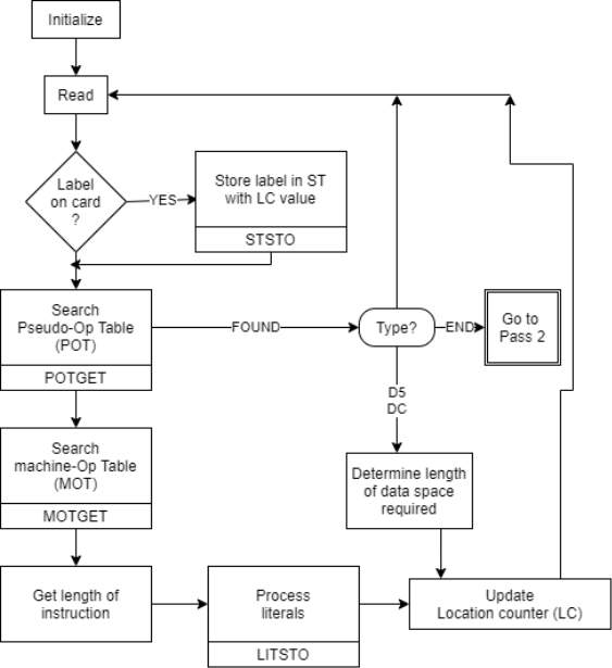
Fig 1: Pass 1 overview: define symbol
Pass II Database
1. Copy of source program input to pass-1
2. Location counter
3. A table the MOT that indicates for each instruction
a. Symbolic
b. Mnemonics
c. Length
d. Binary machine op-code
e. Format (RR, RS, RX, SI, SS)
4. The POT table, which shows the symbolic mnemonic and action to be taken in Pass-2 for each pseudo-op.
5. Pass-1 prepares the ST, which includes each label and its corresponding value.
6. A table, BT, that shows which registers are currently specified by the base register via pseudo-ops and what the contents of these registers are.
7. An INSR work space for storing each instruction as its various parts are put together.
8. A PRINT LINE in the workspace that is used to create a printed listing.
9. A workspace PUNCH CARD used to convert assembled instructions into the format required by the loader prior to actual outputting.
10. An output deck of assembled instruction in the format needed by the loader.
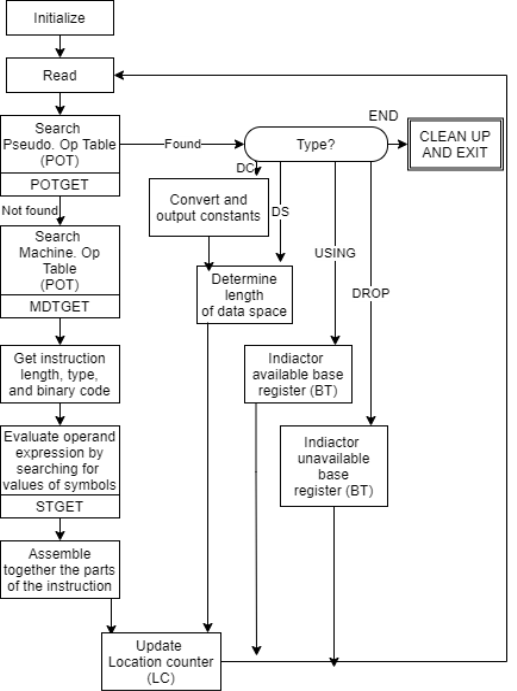
Fig 2: Pass 2 overview: evaluate fields and generate code
Format of Database
The section on data base format and content explains the format and content of each data base, which is a work that must be completed before defining the specific algorithm.
- Algorithms, databases, and formats are all intertwined in reality. When dealing with data bases, the designer keeps some elements of the format and algorithm in mind and iterates until all components work.
- Pass one necessitates a MOT with a name and length, whereas pass two necessitates a MOT with a name, length, binary code, and format.
- For both passes, we can use two tables with different formats and contents, or we can use one table.
- This is also true for POT. By generalizing the table formats, we can also combine the POT and MOT into one table.
- Machine Operation Table (MOT)
Fig machine op table for pass-1 and pass-2 the op code is the key and its value is the binary op-code equivalent which is stored for use in generating machine opcode. The instruction length is saved to update the location counter, and the instruction format is saved to build the machine language equivalent.
2. Pseudo Operation Table (POT)
The physical address will be stored in the table. Each pseudo-op is provided with an accompanying pointer to the assembler procedure for executing the pseudo-op in Fig POT for pass-1.
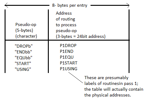
Fig 3: POT for pass 1
3. Symbol Table (ST)
In most cases, the symbol table is hash-organized. It includes all necessary information about the symbols defined and utilized in the source code. For each symbol and address in a symbol table, information about all forward references is created at random, and the information about that symbol gets the same address conflict is resolved using collision handling techniques.
The relative location indicator indicates to the assembler whether the symbol's value is absolute or relative to the program's base.

Fig 4: Symbol table for pass 1 and pass 2
4. Base Table (BT)
The assembler uses the base register table to generate the necessary base register references in machine instructions and to compute the correct offsets. When producing an address, the assembler consults the base register table to select a base register with a value close to the symbolic references. The address refers to the data stored in that base register.
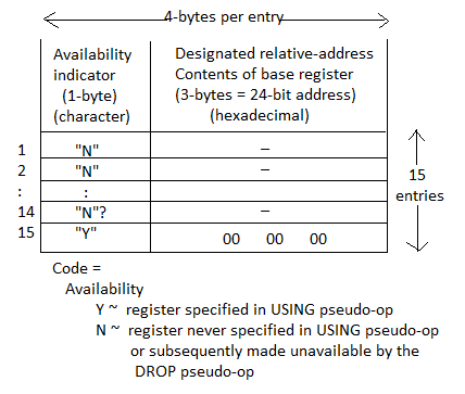
Fig 5: Base table for pass 2
Key takeaway
The symbol table is hash-organized. It includes all necessary information about the symbols defined and utilized in the source code.
The assembler uses the base register table to generate the necessary base register references in machine instructions and to compute the correct offsets.
An assembler is a machine language translator that converts an assembler programme into a machine language programme. The assembler generates machine code for each instruction by going over the programme one line at a time.
Two types of Assemblers
● Single pass assembler
● Two pass assembler
Single pass Assembler
● A one pass assembler examines the programme once and generates the binary equivalent.
● In a single pass, the assembler replaces all symbolic instructions with machine code.
Single pass assemblers are used when
It is required or desired to prevent a second pass through the source programme because the external storage for the intermediate file between the two passes is slow or unpleasant.
Main problem
● Forward references
● Data items
● Labels on instructions
Forward reference problem
● The symbol must be specified someplace in the assembly programme, according to the rules.
● However, a symbol may be used before it is defined in specific instances. This type of reference is known as a forward reference.
● As a result, the assembler is unable to construct the instructions, a condition known as forward referencing.
c=a + b;
Int a;
Int b;
Int c;
Forward reference
Any symbol that hasn't been defined yet
1. Don't translate the address.
2. Insert the symbol into SYMTAB and leave it undefined.
3. The address that refers to the undefined symbol is added to the symbol table entry's list of forward references.
4. When a symbol's definition is found, the symbol's proper address is placed into any instructions previously generated according to the forward reference list.
Solutions for one pass assembler
There are two approaches that can be used:
● Eliminating forward references:
Forward references to data items are either forbidden or all labels used in forward references are defined in the source programme before they are referenced.
● Generating the object code in memory:
There is no need to write an object programme or use a loader. Every time the software is run, it must be reassembled.
Design of 2 Pass Assembler
Tasks performed by the passes of a two pass assembler are:
Pass-1:
● Define symbols and literals, and keep track of them in the symbol and literal tables.
● Keep an eye on the location counter.
● Pseudo-operations are operations that aren't actually done.
Pass-2:
● Convert symbolic op-codes into numeric op-codes to generate object code.
● Create data for literals and look for symbol values.
First, we'll look at a tiny assembly language programme to see how their separate passes function. The following is the format of an assembly language statement:
[Label] [Opcode] [operand]
Example: M ADD R1, ='3'
Where, M - Label; ADD - symbolic opcode;
R1 - symbolic register operand; (='3') - Literal
Assembly Program:
Label Op-code operand LC value(Location counter)
JOHN START 200
MOVER R1, ='3' 200
MOVEM R1, X 201
L1 MOVER R2, ='2' 202
LTORG 203
X DS 1 204
END 205
Let's take a closer look at how this programme operates:
● START - This instruction begins the execution of the programme at address 200, and the label START gives the programme a name. (The program's name is JOHN.)
● MOVER: It moves the content of literal(=’3′) into register operand R1.
● MOVEM: It moves the content of register into memory operand(X).
● MOVER: It again moves the content of literal(=’2′) into register operand R2 and its label is specified as L1.
● LTORG: It assigns address to literals(current LC value).
● DS(Data Space): It assigns a data space of 1 to Symbol X.
● END: It finishes the program execution.
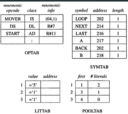
Pass 1 uses the given data structures:
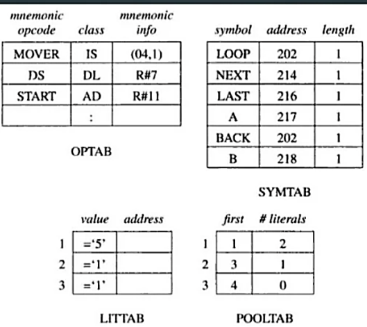
• OPTAB - table of mnemonic opcodes, class (IS,DL,AD) and mnemonic info
• SYMTAB - symbol table
• LITTAB - table of literals used in the program
• POOLTAB - table of information concerning literal pools
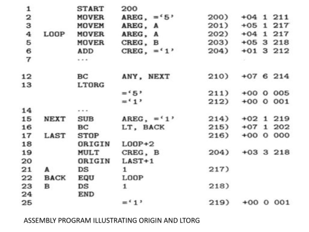
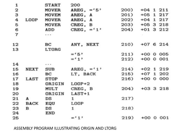
Program example
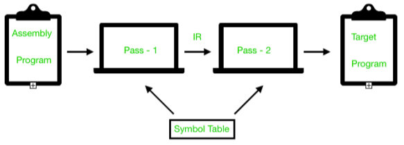
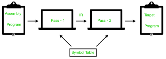
As a whole assembler works as:
Advantages of two pass assembler
One of the key advantages of a Two-Pass Assembler is that the output file is often generated by the first pass of an extreme Two-pass assembler, which is then read by the second pass.
This has the advantage of allowing the first pass to record each line of input, as well as the next position of some or all of the lexemes in that line and some of the parsing results.
In an assembly-level language, for example, each line can be transmitted to the next line by a record indicating whether the line was a definition or a statement, and if it was a statement, whether it had a label, and what the value of the location counter was before processing that line.
The use of such intermediate files can eliminate unnecessary computations in the two-pass assembler but then it adds to the input-output burden of the system.
References:
- John Donovan, “Systems Programming”, McGraw Hill, ISBN 978-0--07-460482-3
- Dhamdhere D., "Systems Programming and Operating Systems", McGraw Hill, ISBN 0 - 07 - 463579 – 4
- Leland Beck, “System Software: An Introduction to Systems Programming”, Pearson
- John R. Levine, Tony Mason, Doug Brown, “Lex & Yacc”, 1st Edition, O’REILLY, ISBN 81-7366-062-X
Unit - 2
Assembler
1. Compilers and Assemblers
- AN program or that of a compiler is simply another program that may execute on your ADPS.
- The sole issue special that of AN program or that of a compiler is that it interprets programs from that of the one type (source code) to a different (machine code).
- A typical that of the x86 program, as an example, would browse that of the lines of text with that of the x86 directions, take apart every of that of the statement, so write the binary equivalent of every of that of the instruction on to memory or thereto that of a file for later execution.
- Assemblers have 2 massive blessings over committal to writing in machine code:
- First, they mechanically translate strings like
- Add ax, bx
- Mov ax, [1000h]
To their corresponding binary type.
- Second, and doubtless even that of the additional necessary, assemblers allow you to attach labels to that of the statements so consult with them in this of a jump directions
(A coder won't ought to recognize the target address of AN instruction once specifying targets of jump directions.)
2. The Assembly method
1. Aggregation the ASCII text file into that of AN object file
2. Linking the article file thereupon of the opposite modules or the libraries into AN workable program
3. Loading the program into memory
4. Running the program
3. Tiny Assembly Sample
; add_16_bytes.asm
;
.586P
; Flat memory model, normal career convention:
.MODEL FLAT, STDCALL
;
; knowledge section
_DATA section
Values sound unit sixteen DUP( five ) ; 16 bytes of values "5"
_DATA ENDS
; Code section
_TEXT section
START:
Mov eax, zero ; clear result
Mov bl, sixteen ; init loop counter
Lea esi, values ; init knowledge pointer
Addup:
Add al, [esi] ; add computer memory unit to add
INC esi ; increment knowledge pointer
Dec bl ; decrement loop counter
Jnz addup ; if BL not zero, continue
Mov [esi], al ; save add
Dowse ; Exit
_TEXT ENDS
END START
- Listing file: add_16_bytes.lst
4. MASM statement Interface
- To assemble which of the run AN program program named myprog.asm, sort the subsequent commands:
- Decision "C:\Program Files\Microsoft Visual Studio 8\Common7\Tools\vsvars32.bat"
- Cubic centimetre /coff /c /Fl myprog.asm
- LINK /debug /subsystem:console /entry:start /out:myprog.exe myprog.obj ..\iolib\io.obj kernel32.lib
- Myprog.exe
5. Assembling
- At assembly time, the assembler:
o Evaluates conditional-assembly directives, aggregation if the conditions are true.
o Expands macros and that of the macro functions.
o Evaluates constant expressions like MYFLAG AND 80H, subbing the calculated worth for the expression.
o Encodes directions and non address operands. As an example, mov cx, 13; are often encoded at assembly time as a result of the instruction doesn't access memory.
o Saves memory offsets as that of the offsets from their segments.
o Places sections and segment attributes within the object file.
o Saves placeholders for that of the offsets and that of the segments (relocatable addresses).
o Outputs an inventory if requested.
o Passes messages (such as INCLUDELIB) on to the linker.
6. Linking
- Once your ASCII text file is assembled thereto of the ensuing object file is passed to that of the linker. At this time, the linker is also mix many object files into that of AN workable program. The linker:
o Combines segments in keeping with the directions within the object files, rearranging the positions of segments that share constant category or cluster.
o Fills in placeholders for offsets (relocatable addresses).
o Writes relocations for segments into the header of .EXE files (but not .COM files).
o Writes the result as AN workable program file.
7. Loading
- When loading that of the workable file into the memory, the in that of the operation system:
o Creates that of the program section prefix (PSP) header in that of the memory.
o Allocates memory for that of the program, supported the values within that of the PSP.
o Masses the program.
o Calculates the right values for absolute addresses from the relocation table.
o Masses the section registers SS, CS, DS, and Es with values that time to the correct areas of memory.
8. Helpful Tools and Utilities
- DUMPBIN dismantlement program
- Debuggers: OllyDbg and WinDbg
- Consol I/O: iolib.
Label
Symbolic labeling of an assembler address (command address at Machine level)
Mnemomic
Symbolic description of an operation
Operands
Contains of variables or addressee if necessary
Comments
Optional field
Statement format An Assembly language statement has following format:
[Label] <opcode> <operand spec>[,<operand spec>..]
If a label is specified in a statement, it is associated as a symbolic name with the memory word generated for the statement.
<operand spec> has the following syntax:
<symbolic name> [+<displacement>] [(<index register>)]
Eg. AREA, AREA+5, AREA(4), AREA+5(4)
AREA – memory word with which name AREA is associated
AREA +5 : The memory word, which is 5 words away from the word which name is AREA, here ’5’ is displacement offset from AREA
AREA(4) : indexing with index register 4 : the operand address is obtained by adding the content of index register 4 to the address of area
Structures of Data The establishment of a data base with which our assembler will work is the second phase in our assembler design.
Pass I - Database
1. Run the source code.
2. A counter that keeps track of where each instruction is located.
3. A table, the machine-operation table (MOT), that shows the symbolic mnemonics for each instruction as well as the duration of the instruction (tow, four or six bytes).
4. The pseudo operation table (POT), which lists the symbolic mnemonics and actions to be performed for each pseudo-op in pass-1.
5. A table called the literal table (LT), which is used to keep track of each literal encounter and its allocated position.
6. A table called the symbol table (ST), which is used to keep track of each label and its associated value.
7. A copy of the input for Pass-2 to use later. This could be saved on a separate storage device.
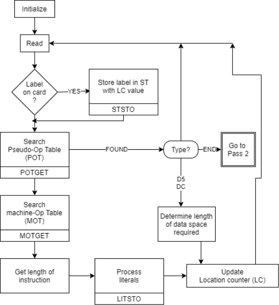
Fig 1: Pass 1 overview: define symbol
Pass II Database
1. Copy of source program input to pass-1
2. Location counter
3. A table the MOT that indicates for each instruction
a. Symbolic
b. Mnemonics
c. Length
d. Binary machine op-code
e. Format (RR, RS, RX, SI, SS)
4. The POT table, which shows the symbolic mnemonic and action to be taken in Pass-2 for each pseudo-op.
5. Pass-1 prepares the ST, which includes each label and its corresponding value.
6. A table, BT, that shows which registers are currently specified by the base register via pseudo-ops and what the contents of these registers are.
7. An INSR work space for storing each instruction as its various parts are put together.
8. A PRINT LINE in the workspace that is used to create a printed listing.
9. A workspace PUNCH CARD used to convert assembled instructions into the format required by the loader prior to actual outputting.
10. An output deck of assembled instruction in the format needed by the loader.
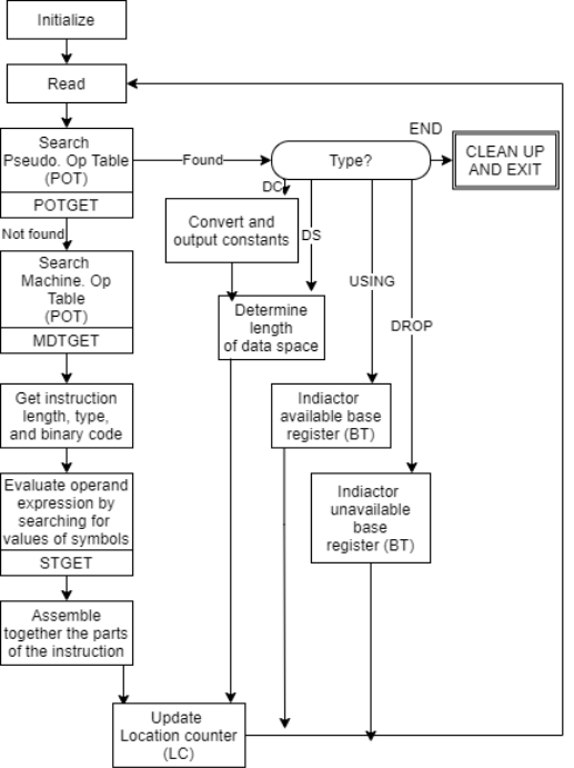
Fig 2: Pass 2 overview: evaluate fields and generate code
Format of Database
The section on data base format and content explains the format and content of each data base, which is a work that must be completed before defining the specific algorithm.
- Algorithms, databases, and formats are all intertwined in reality. When dealing with data bases, the designer keeps some elements of the format and algorithm in mind and iterates until all components work.
- Pass one necessitates a MOT with a name and length, whereas pass two necessitates a MOT with a name, length, binary code, and format.
- For both passes, we can use two tables with different formats and contents, or we can use one table.
- This is also true for POT. By generalizing the table formats, we can also combine the POT and MOT into one table.
- Machine Operation Table (MOT)
Fig machine op table for pass-1 and pass-2 the op code is the key and its value is the binary op-code equivalent which is stored for use in generating machine opcode. The instruction length is saved to update the location counter, and the instruction format is saved to build the machine language equivalent.
2. Pseudo Operation Table (POT)
The physical address will be stored in the table. Each pseudo-op is provided with an accompanying pointer to the assembler procedure for executing the pseudo-op in Fig POT for pass-1.
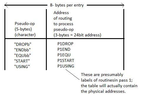
Fig 3: POT for pass 1
3. Symbol Table (ST)
In most cases, the symbol table is hash-organized. It includes all necessary information about the symbols defined and utilized in the source code. For each symbol and address in a symbol table, information about all forward references is created at random, and the information about that symbol gets the same address conflict is resolved using collision handling techniques.
The relative location indicator indicates to the assembler whether the symbol's value is absolute or relative to the program's base.

Fig 4: Symbol table for pass 1 and pass 2
4. Base Table (BT)
The assembler uses the base register table to generate the necessary base register references in machine instructions and to compute the correct offsets. When producing an address, the assembler consults the base register table to select a base register with a value close to the symbolic references. The address refers to the data stored in that base register.
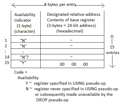
Fig 5: Base table for pass 2
Key takeaway
The symbol table is hash-organized. It includes all necessary information about the symbols defined and utilized in the source code.
The assembler uses the base register table to generate the necessary base register references in machine instructions and to compute the correct offsets.
An assembler is a machine language translator that converts an assembler programme into a machine language programme. The assembler generates machine code for each instruction by going over the programme one line at a time.
Two types of Assemblers
● Single pass assembler
● Two pass assembler
Single pass Assembler
● A one pass assembler examines the programme once and generates the binary equivalent.
● In a single pass, the assembler replaces all symbolic instructions with machine code.
Single pass assemblers are used when
It is required or desired to prevent a second pass through the source programme because the external storage for the intermediate file between the two passes is slow or unpleasant.
Main problem
● Forward references
● Data items
● Labels on instructions
Forward reference problem
● The symbol must be specified someplace in the assembly programme, according to the rules.
● However, a symbol may be used before it is defined in specific instances. This type of reference is known as a forward reference.
● As a result, the assembler is unable to construct the instructions, a condition known as forward referencing.
c=a + b;
Int a;
Int b;
Int c;
Forward reference
Any symbol that hasn't been defined yet
1. Don't translate the address.
2. Insert the symbol into SYMTAB and leave it undefined.
3. The address that refers to the undefined symbol is added to the symbol table entry's list of forward references.
4. When a symbol's definition is found, the symbol's proper address is placed into any instructions previously generated according to the forward reference list.
Solutions for one pass assembler
There are two approaches that can be used:
● Eliminating forward references:
Forward references to data items are either forbidden or all labels used in forward references are defined in the source programme before they are referenced.
● Generating the object code in memory:
There is no need to write an object programme or use a loader. Every time the software is run, it must be reassembled.
Design of 2 Pass Assembler
Tasks performed by the passes of a two pass assembler are:
Pass-1:
● Define symbols and literals, and keep track of them in the symbol and literal tables.
● Keep an eye on the location counter.
● Pseudo-operations are operations that aren't actually done.
Pass-2:
● Convert symbolic op-codes into numeric op-codes to generate object code.
● Create data for literals and look for symbol values.
First, we'll look at a tiny assembly language programme to see how their separate passes function. The following is the format of an assembly language statement:
[Label] [Opcode] [operand]
Example: M ADD R1, ='3'
Where, M - Label; ADD - symbolic opcode;
R1 - symbolic register operand; (='3') - Literal
Assembly Program:
Label Op-code operand LC value(Location counter)
JOHN START 200
MOVER R1, ='3' 200
MOVEM R1, X 201
L1 MOVER R2, ='2' 202
LTORG 203
X DS 1 204
END 205
Let's take a closer look at how this programme operates:
● START - This instruction begins the execution of the programme at address 200, and the label START gives the programme a name. (The program's name is JOHN.)
● MOVER: It moves the content of literal(=’3′) into register operand R1.
● MOVEM: It moves the content of register into memory operand(X).
● MOVER: It again moves the content of literal(=’2′) into register operand R2 and its label is specified as L1.
● LTORG: It assigns address to literals(current LC value).
● DS(Data Space): It assigns a data space of 1 to Symbol X.
● END: It finishes the program execution.
Pass 1 uses the given data structures:
• OPTAB - table of mnemonic opcodes, class (IS,DL,AD) and mnemonic info
• SYMTAB - symbol table
• LITTAB - table of literals used in the program
• POOLTAB - table of information concerning literal pools
Program example
As a whole assembler works as:
Advantages of two pass assembler
One of the key advantages of a Two-Pass Assembler is that the output file is often generated by the first pass of an extreme Two-pass assembler, which is then read by the second pass.
This has the advantage of allowing the first pass to record each line of input, as well as the next position of some or all of the lexemes in that line and some of the parsing results.
In an assembly-level language, for example, each line can be transmitted to the next line by a record indicating whether the line was a definition or a statement, and if it was a statement, whether it had a label, and what the value of the location counter was before processing that line.
The use of such intermediate files can eliminate unnecessary computations in the two-pass assembler but then it adds to the input-output burden of the system.
References:
- John Donovan, “Systems Programming”, McGraw Hill, ISBN 978-0--07-460482-3
- Dhamdhere D., "Systems Programming and Operating Systems", McGraw Hill, ISBN 0 - 07 - 463579 – 4
- Leland Beck, “System Software: An Introduction to Systems Programming”, Pearson
- John R. Levine, Tony Mason, Doug Brown, “Lex & Yacc”, 1st Edition, O’REILLY, ISBN 81-7366-062-X