Unit - 4
Linker and Loader
The loader is a program which takes this object program, prepares it for execution, and loads this executable code of the source into memory for execution.
Definition
Loader is utility program which takes object code as input prepares it for execution and loads the executable code in to the memory. Thus loader is actually responsible for initiating the execution process.
Functions of loader
The loader is responsible for the activities such as allocation, linking, relocation and loading
1) It allocates the space for the program in the memory, by calculating the size of the program. This activity is called allocation.
2) It resolves the symbolic references (code/data) between the object modules by assigning all the user subroutine and library subroutine addresses. This activity is called linking.
3) There are some address dependent locations in the program, such address constants must be adjusted according to allocated space, such activity done by loader is called relocation.
4) Finally it places all the machine instructions and data of corresponding programs and subroutines into the memory. Thus the program now becomes ready for execution.
Key takeaway
The loader is a program which takes this object program, prepares it for execution, and loads this executable code of the source into memory for execution.
Loader is utility program which takes object code as input prepares it for execution and loads the executable code in to the memory.
A loader's tasks include the following:
● Check the software for memory needs, permissions, and other issues.
● Copy necessary files from the disc into memory, such as the programme image or required libraries.
● Add the necessary command-line parameters to the stack.
● Link the program's start point as well as any other libraries that are required.
● Set up the registers.
● Return to the memory location where the programme began.
Function of loader
The loader is in charge of tasks like allocation, linking, relocation, and loading.
● Allocation - Allocation is the process of allocating memory space for a programme based on the size of the programme.
● Linking - It resolves the object's symbolic references (code/data).
● Relocation - Address-dependent locations in the programme must be relocated, and address constants must be modified according to available space.
● Loading - Loading is the process of physically putting all of the machine instructions and data into memory.
(a) Program Relocation
– Performing Relocation
(b) Linking
– EXTERN & ENTRY statement
– Resolving external references
– Binary Programs
(c) Object Module
Program Relocation
Address Sensitive Program:
● AA - Absolute Addresses, which can be either instruction or data addresses.
● AA ≠ ф; indicates that instructions or data are stored in memory words with a certain address.
● This type of programme is known as an address sensitive programme, and it has the following elements:
○ Address Sensitive Instruction: an instruction which contains address ai Є AA.
○ Address Constant: a data word containing an ai Є AA address.
● Important: Address Sensitive Program P can only run correctly if the memory space allocated to it has the same start address as its translated origin.
● As a result, each address-sensitive instruction of P must be 'corrected' in order to execute appropriately from any memory location.
● Def: Program Relocation: Is the process of changing the address in address sensitive instructions so that the programme can run appropriately from the specified memory location.
● Linker performs relocation if
○ Linked Origin ≠ Translated Origin
● Loader performs relocation if
○ Load Origin ≠ Linked Origin
● In general, a linker will always relocate a file, although some loaders will not.
● Absolute loaders don't relocate anything, therefore
○ Load Origin = Linked Origin
○ Thus, Load Origin and Linked Origin are used interchangeably.
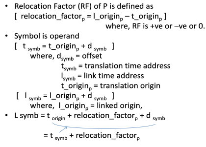
Performing Relocation
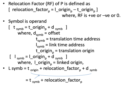
IRR: Instruction Requiring Relocation
● It's a series of instructions in programme p that effect relocation.
● Steps:
○ Calculate the Relocation Factor (RF).
○ For each instruction that is a member of IIR, add it to the Translation Time Address(es).
● Eg: relocation factor = 900 -500 = 400
IRR contains translation addresses 540 & 538
(instruction: read A)
Address is changed to 540 + 400 = 940 and
538 + 400 = 938
Linking
● SP = Pi is an Application Program that consists of a Set of Program Units.
● Using Pj's instructions and addresses, a programme unit Pi communicates with another programme unit Pj.
● This necessitates the following:
○ Public Definition: pub symb is a symbol defined in a programme unit that can be referenced by other programmes.
○ External Reference: a reference to ext symb, a symbol not defined in the programme unit containing the reference.
● Who will be in charge of these two situations?
EXTRN & ENTRY statements:
● The public definition of programme unit is provided in the ENTRY statement.
○ That is, it lists the symbols defined in one programme unit that may be referenced in another.
● The EXTRN statement lists the symbols in the programme unit to which external references are made.
● Example
○ THE ENTRY STATEMENT IS TOTAL. (as defined by the general population)
○ EXTRN statements MAX and ALPHA (external reference)
○ Because the assembler does not know the location of the EXTRN symb, it places a 0 in the address field of the instruction wherever these symb are found.
○ What happens if we don't use EXTRN stmts to refer to these variables? Assembler throws errors.
○ As a result, resolving external references becomes necessary.
Resolving External Reference:
● Every external reference should be bound to the correct link time address before the AP (application programme) runs.
● Who will be responsible for the binding?
○ Linker now enters the picture.
● Linking is the process of binding an external reference to the proper link time address.
● An external reference is considered to be unresolved until it is linked, and then resolved once it is.
Binary program
● Is a programme written in machine language that consists of a set of programme units SP such that for any Pi Є SP,
○ Pi relocated at link origin.
○ Linking is performed for each external reference in Pi
● Linker Command:
Linker <link origin> <object module names>
[, <execution start address> ]
● The linker transforms an object module into a set of programme units (SP), which is then converted into a binary programme.
● If link address = load address, A loader is a programme that loads a binary file into a memory location where it can be executed.
Object module
● The Object Module (OM) contains all of the data required to move and link the programme to other programmes.
● OM is made up of four parts:
○ Header: P's translation origin, size, and execution start address are all contained in the header.
○ Program: This file contains the machine language programme for P.
○ Relocation Table (RELOCTAB): This table describes IRRp (Instruction Requiring Relocation). 'Translated Address' - of address sensitive instruction - is a field in each entry.
○ Linking Table: (LINKTAB) contains public definition and external reference information. There are three fields:
■ Symbol: a name with a symbolic meaning.
■ Type: PD/EXT, which stands for "public definition" or "external reference."
■ Translated Address: If PD, this is the address of the first memory word that has been allocated. If EXT, the address of the memory word containing the symbol reference.
In this type of loader, the instruction is read line by line, its machine code is obtained and it is directly put in the main memory at some known address. That means the assembler runs in one part of memory and the assembled machine instructions and the data is directly put into their assigned memory locations. After completion of the assembly process, assign the starting address of the program to the location counter.
The typical example is WATFOR-77, it’s a FORTRAN compiler which uses such “load and go” scheme.
“Assembler-and-go” is another name for compile and go loader. To comprehend the various loader schemes, the concept "segment" must be introduced. A segment is a single source or object deck that corresponds to a single unit of information, such as a program or data. The compile and go loader is depicted in a diagram.
The compile and go loader runs the assembler program in one section of memory and then loads the completed machine instructions and data into their respective memory regions. Once the assembly is complete, the assembler passes control to the program's starting instruction.
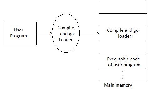
Fig 1: Compile and go
Advantages:
This scheme is simple to implement. Because assembler is placed at one part of the memory and loader simply loads assembled machine instructions into the memory.
Disadvantages:
- In this scheme some portion of memory is occupied by assembler which is simply wastage of memory. As this scheme is combination of assembler and loader activities, this combination program occupies large block of memory.
- There is no production of .obj file, the source code is directly converted to executable form. Hence even though there is no modification in the source program it needs to be assembled and executed each time, which then becomes a time consuming activity.
- It cannot handle multiple source programs or multiple programs written in different languages. This is because assembler can translate one source language to other target language.
- For a programmer it is very difficult to make an orderly modulator program and also it becomes difficult to maintain such program, and the “compile and go” loader cannot handle such programs.
- The execution time will be more in this scheme as every time program is assembled and then executed
Key takeaway
“Assembler-and-go” is another name for compile and go loader. To comprehend the various loader schemes, the concept "segment" must be introduced.
In this loader scheme, the source program is converted to object program by some translator (assembler). The loader accepts these object modules and puts machine instruction and data in an executable form at their assigned memory. The loader occupies some portion of main memory.
Advantages:
● The program need not be retranslated each time while running it. This is because initially when source program gets executed an object program gets generated. Of program is not modified, then loader can make use of this object program to convert it to executable form.
● There is no wastage of memory, because assembler is not placed in the memory, instead of it, loader occupies some portion of the memory. And size of loader is smaller than assembler, so more memory is available to the user.
● It is possible to write source program with multiple programs and multiple languages, because the source programs are first converted to object programs always, and loader accepts these object modules to convert it to executable form.
The following diagram shows the functionalities of general loader.
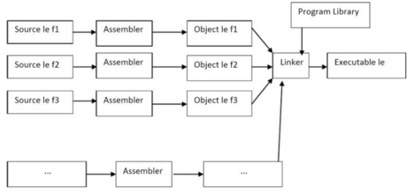
Fig 2: General loader
Key takeaway
In this loader scheme, the source program is converted to object program by some translator (assembler). The loader accepts these object modules and puts machine instruction and data in an executable form at their assigned memory.
Absolute loader is a kind of loader in which relocated object files are created, loader accepts these files and places them at specified locations in the memory. This type of loader is called absolute because no relocation information is needed; rather it is
Obtained from the programmer or assembler. The starting address of every module is known to the programmer, this corresponding starting address is stored in the object file, then task of loader becomes very simple and that is to simply place the executable form of the machine instructions at the locations mentioned in the object File.
In this scheme, the programmer or assembler should have knowledge of memory management. The resolution of external references or linking of different subroutines are the issues which need to be handled by the programmer. The programmer should take care of two things: first thing is specification of starting
Address of each module to be used. If some modification is done in some module then the length of that module may vary.
This causes a change in the starting address of immediate next modules, its then the programmer’s duty to make necessary changes in the starting addresses of respective modules. Second thing is, while branching from one segment to another the absolute starting address of respective module is to be known by the programmer so that such address can be specified at respective JMP instructions.
For example
Line number
1 MAIN START 1000
1 JMP 5000
16 STORE instruction at location 2000
END
1 SUM START 5000
2
20 JMP 2000
21 END
In this example there are two segments, which are interdependent. At line number 1 the assembler directive START specifies the physical starting address that can be used during the execution of the first segment MAIN.
Then at line number 15 the JMP instruction is given which specifies the physical starting address that can be used by the second segment. The assembler creates the object codes for these two segments by considering the stating addresses of these two segments. During the execution, the first segment will be loaded at address 1000 and second segment will be loaded at address 5000 as specified by the programmer. Thus the problem of linking is manually solved by the programmer itself by taking care of the mutually dependent dresses.
As you can notice that the control is correctly transferred to the address 5000 for invoking the other segment, and after that at line number 20 the JMP instruction transfers the control to the location 2000, necessarily at location 2000 the instruction STORE of line number 16 is present. Thus resolution of mutual references and linking is done by the programmer.
The task of assembler is to create the object codes for the above segments and along with the information such as starting address of the memory where actually the object code can be placed at the time of execution. The absolute loader accepts these object modules from assembler and by reading the information about their starting addresses, it will actually place (load) them in the memory at the specified address.
Advantages
- It is easy to implement
- This scheme allows multiple programs in different languages.
- The task of loader becomes simpler as its simply obeys the instruction regarding where to place the object code in memory.
- The process of execution is efficient.
Disadvantages
- The programmer should specify the address in core where the application should be loaded.
- If the program contains many subroutines, the programmer must remember the address of each one.
- Additionally, the programmer must use each absolute address explicitly in the other subroutines in order to maintain subroutine linkage.
- Overlapping
Absolute loader algorithm:
Begin
Read header record
Verify program name and length
Read first TEXT record
While record type !=E
Do begin
{If object code is in character form, convert into internal representation} Move object code to
Specified location in memory
Read the next object program record
End
Jump to address specified in END record end
Key takeaway
Absolute loader is a kind of loader in which relocated object files are created, loader accepts these files and places them at specified locations in the memory.
This type of loader is called absolute because no relocation information is needed; rather it is obtained from the programmer or assembler.
When a single subroutine is altered, relocating loaders was introduced to prevent the need for all subroutines to be reassembled. It also allows you to do the programmer's allocation and linking chores. The Binary Symbolic Subroutine (BSS) loader is an example of moving loaders. Despite the fact that the BSS loader only allows for one common data segment, it does allow for multiple procedure segments. This type of loader's assembler assembles each procedure segment separately and delivers the text and data to relocation and intersegment references.
In this technique, the assembler generates text as an output for each source program. The output text is prefixed with a transfer vector containing addresses, which includes names of the subroutines referenced by the source program. The loader would also receive other information from the assembler, such as the length of the entire program and the length of the transfer vector component.
The text and the transfer vector are loaded into the core after this information is provided. The loader would next load each subroutine that has been identified in the transfer vector. For each entry in the transfer vector, a transfer instruction would be placed in the relevant subroutine.
The object program and information about all the programs to which it refers are the outputs of the relocating assembler. It also includes relocation information for the locations that must be altered before it can be put into the core. This placement in the core could be arbitrary, such as the places that are depending on the core allocation. In computers having a fixed-length direct-address instruction format, the BSS loader technique is most commonly utilized.
Consider the following example of the 360 RX instruction format:

The 16-bit absolute address of the operand is A2 in this format, which is the direct address instruction format. Every instruction should have the address section relocated. As a result, computers with direct-address instruction formats have far more serious issues than computers with 360-type base registers. The problem is solved using relocation bits in 360-type base registers. The assembler associates a bit with each instruction or address field, and the relocation bits are included in the object desk. If the associated bit is one, the corresponding address field for each instruction must be relocated; otherwise, this field is not relocated.
Key takeaway
When a single subroutine is altered, relocating loaders was introduced to prevent the need for all subroutines to be reassembled. It also allows you to do the programmer's allocation and linking chores.
Used Data structures required for designing two pass direct linking loader scheme
Pass 1 database
1. Input object deck
2. A parameter initial program load address(IPLA)
3. A program load address Counter(PLA) used to keep track of each segment assigned location
4. A table the global external symbol table(GEST) that is used to store each external symbol and its corresponding assigned core address.
5. A copy of input later used by pass2
6. A printed Iisting Joad map that specifies each external symbol and its assigned value.
Pass 2 database
1. A copy of object program
2. The initial program load address parameter(IPLA)
3. The program load address Counter(PLA)
4. The global external symbol table prepared by passl
5. An array, the local external symbol array(LESA) which is used to establish a correspondence between ESD ID numbers ,used on ESD and RLD cards, cards and the corresponding external symbol absolute address value.
The following diagram shows two pass direct linking loader scheme
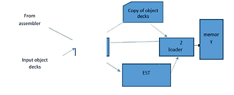
Fig 3: Two pass direct linking loader scheme
Pass I algorithm-allocate segments and define symbols
The purpose of first pass is to assign a location to each segment, and thus to define the values of all external symbols. Since we wish to minimize the amount of core storage required for the total program, we will assign each segment the next available location after the preceding segment. It is necessary for the loader to know where it can load the first segment.
Initially, the PLA is set to initial program load address (IPLA). An object card is then read and a copy written for use by pass2. The card can be one of four types, ESD,TXT,RLD, and END. If it is a TXT or RLD card, there is no processing required during passl so the next card is read. An ESD card is processed in different ways depending upon the type of external symbol, SD,LD. If a segment definition ESD card is read, the length field, LENGTH from the card is temporarily saved in the variable SLENGTH.
The VALUE assigned to this symbol is set to be current value of PLA. The symbol and its assigned value are then stored in the GEST. If the symbol already existed in the GEST then error. The symbol and its value are printed as part of the load map. A similar process is used for LD symbols. The value to be assigned is set to the current PLA plus the relative address ADDR indicated on the ESD card. The ER symbols do not require any processing during pass l. When an END card is encountered, the PLA is incremented by the length of the segment and saved in SLENGTH becoming PLA for the next segment. When an EOF is finally read, pass 1 is completed and control transfer to pass2.
Pass 2 algorithm-load text and relocate /link address constants
After all the segments have been assigned locations and the external symbols have been defined by pass l, it is possible to complete the loading by loading the text and adjusting address constants. At the end of pass2, the loader will transfer control to the loaded program. At the beginning of pass2, initialize IPLA. The cards are read and different types of card are processed accordingly.
Difference between linker and loader
S.no. | LINKER | LOADER |
1 | Linker's primary role is to create executable files. | Loader's primary goal is to load executable files into main memory. |
2 | The linker accepts object code generated by the compiler/assembler as input. | The loader, on the other hand, takes executable files generated by the linker as input. |
3 | Linking is the process of putting together multiple pieces of code and source code to create executable code. | The process of loading executable programmes into main memory for further execution is known as loading. |
4 | There are two sorts of linkers: Linkage Editor and Dynamic Linker. | Absolute, Relocating, Direct Linking, and Bootstrap are the four types of loaders. |
5 | The linker can also be used to assemble all object modules. | It aids in the assignment of addresses to executable codes and files. |
6 | The linker is also in charge of ordering things in the address space of a programme. | The loader is also in charge of modifying references used within the application. |
References:
- Silberschatz, Galvin, Gagne, "Operating System Principles", 9th Edition, Wiley, ISBN 978- 1-118-06333-0
- Alfred V. Aho, Ravi Sethi, Reffrey D. Ullman, “Compilers Principles, Techniques, and Tools”, Addison Wesley, ISBN 981-235-885-4
- Leland Beck, “System Software: An Introduction to Systems Programming”, Pearson
- John Donovan, “Systems Programming”, McGraw Hill, ISBN 978-0--07-460482-3
Unit - 4
Linker and Loader
The loader is a program which takes this object program, prepares it for execution, and loads this executable code of the source into memory for execution.
Definition
Loader is utility program which takes object code as input prepares it for execution and loads the executable code in to the memory. Thus loader is actually responsible for initiating the execution process.
Functions of loader
The loader is responsible for the activities such as allocation, linking, relocation and loading
1) It allocates the space for the program in the memory, by calculating the size of the program. This activity is called allocation.
2) It resolves the symbolic references (code/data) between the object modules by assigning all the user subroutine and library subroutine addresses. This activity is called linking.
3) There are some address dependent locations in the program, such address constants must be adjusted according to allocated space, such activity done by loader is called relocation.
4) Finally it places all the machine instructions and data of corresponding programs and subroutines into the memory. Thus the program now becomes ready for execution.
Key takeaway
The loader is a program which takes this object program, prepares it for execution, and loads this executable code of the source into memory for execution.
Loader is utility program which takes object code as input prepares it for execution and loads the executable code in to the memory.
A loader's tasks include the following:
● Check the software for memory needs, permissions, and other issues.
● Copy necessary files from the disc into memory, such as the programme image or required libraries.
● Add the necessary command-line parameters to the stack.
● Link the program's start point as well as any other libraries that are required.
● Set up the registers.
● Return to the memory location where the programme began.
Function of loader
The loader is in charge of tasks like allocation, linking, relocation, and loading.
● Allocation - Allocation is the process of allocating memory space for a programme based on the size of the programme.
● Linking - It resolves the object's symbolic references (code/data).
● Relocation - Address-dependent locations in the programme must be relocated, and address constants must be modified according to available space.
● Loading - Loading is the process of physically putting all of the machine instructions and data into memory.
(a) Program Relocation
– Performing Relocation
(b) Linking
– EXTERN & ENTRY statement
– Resolving external references
– Binary Programs
(c) Object Module
Program Relocation
Address Sensitive Program:
● AA - Absolute Addresses, which can be either instruction or data addresses.
● AA ≠ ф; indicates that instructions or data are stored in memory words with a certain address.
● This type of programme is known as an address sensitive programme, and it has the following elements:
○ Address Sensitive Instruction: an instruction which contains address ai Є AA.
○ Address Constant: a data word containing an ai Є AA address.
● Important: Address Sensitive Program P can only run correctly if the memory space allocated to it has the same start address as its translated origin.
● As a result, each address-sensitive instruction of P must be 'corrected' in order to execute appropriately from any memory location.
● Def: Program Relocation: Is the process of changing the address in address sensitive instructions so that the programme can run appropriately from the specified memory location.
● Linker performs relocation if
○ Linked Origin ≠ Translated Origin
● Loader performs relocation if
○ Load Origin ≠ Linked Origin
● In general, a linker will always relocate a file, although some loaders will not.
● Absolute loaders don't relocate anything, therefore
○ Load Origin = Linked Origin
○ Thus, Load Origin and Linked Origin are used interchangeably.
Performing Relocation
IRR: Instruction Requiring Relocation
● It's a series of instructions in programme p that effect relocation.
● Steps:
○ Calculate the Relocation Factor (RF).
○ For each instruction that is a member of IIR, add it to the Translation Time Address(es).
● Eg: relocation factor = 900 -500 = 400
IRR contains translation addresses 540 & 538
(instruction: read A)
Address is changed to 540 + 400 = 940 and
538 + 400 = 938
Linking
● SP = Pi is an Application Program that consists of a Set of Program Units.
● Using Pj's instructions and addresses, a programme unit Pi communicates with another programme unit Pj.
● This necessitates the following:
○ Public Definition: pub symb is a symbol defined in a programme unit that can be referenced by other programmes.
○ External Reference: a reference to ext symb, a symbol not defined in the programme unit containing the reference.
● Who will be in charge of these two situations?
EXTRN & ENTRY statements:
● The public definition of programme unit is provided in the ENTRY statement.
○ That is, it lists the symbols defined in one programme unit that may be referenced in another.
● The EXTRN statement lists the symbols in the programme unit to which external references are made.
● Example
○ THE ENTRY STATEMENT IS TOTAL. (as defined by the general population)
○ EXTRN statements MAX and ALPHA (external reference)
○ Because the assembler does not know the location of the EXTRN symb, it places a 0 in the address field of the instruction wherever these symb are found.
○ What happens if we don't use EXTRN stmts to refer to these variables? Assembler throws errors.
○ As a result, resolving external references becomes necessary.
Resolving External Reference:
● Every external reference should be bound to the correct link time address before the AP (application programme) runs.
● Who will be responsible for the binding?
○ Linker now enters the picture.
● Linking is the process of binding an external reference to the proper link time address.
● An external reference is considered to be unresolved until it is linked, and then resolved once it is.
Binary program
● Is a programme written in machine language that consists of a set of programme units SP such that for any Pi Є SP,
○ Pi relocated at link origin.
○ Linking is performed for each external reference in Pi
● Linker Command:
Linker <link origin> <object module names>
[, <execution start address> ]
● The linker transforms an object module into a set of programme units (SP), which is then converted into a binary programme.
● If link address = load address, A loader is a programme that loads a binary file into a memory location where it can be executed.
Object module
● The Object Module (OM) contains all of the data required to move and link the programme to other programmes.
● OM is made up of four parts:
○ Header: P's translation origin, size, and execution start address are all contained in the header.
○ Program: This file contains the machine language programme for P.
○ Relocation Table (RELOCTAB): This table describes IRRp (Instruction Requiring Relocation). 'Translated Address' - of address sensitive instruction - is a field in each entry.
○ Linking Table: (LINKTAB) contains public definition and external reference information. There are three fields:
■ Symbol: a name with a symbolic meaning.
■ Type: PD/EXT, which stands for "public definition" or "external reference."
■ Translated Address: If PD, this is the address of the first memory word that has been allocated. If EXT, the address of the memory word containing the symbol reference.
In this type of loader, the instruction is read line by line, its machine code is obtained and it is directly put in the main memory at some known address. That means the assembler runs in one part of memory and the assembled machine instructions and the data is directly put into their assigned memory locations. After completion of the assembly process, assign the starting address of the program to the location counter.
The typical example is WATFOR-77, it’s a FORTRAN compiler which uses such “load and go” scheme.
“Assembler-and-go” is another name for compile and go loader. To comprehend the various loader schemes, the concept "segment" must be introduced. A segment is a single source or object deck that corresponds to a single unit of information, such as a program or data. The compile and go loader is depicted in a diagram.
The compile and go loader runs the assembler program in one section of memory and then loads the completed machine instructions and data into their respective memory regions. Once the assembly is complete, the assembler passes control to the program's starting instruction.
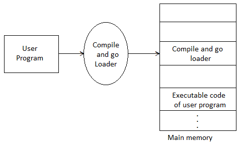
Fig 1: Compile and go
Advantages:
This scheme is simple to implement. Because assembler is placed at one part of the memory and loader simply loads assembled machine instructions into the memory.
Disadvantages:
- In this scheme some portion of memory is occupied by assembler which is simply wastage of memory. As this scheme is combination of assembler and loader activities, this combination program occupies large block of memory.
- There is no production of .obj file, the source code is directly converted to executable form. Hence even though there is no modification in the source program it needs to be assembled and executed each time, which then becomes a time consuming activity.
- It cannot handle multiple source programs or multiple programs written in different languages. This is because assembler can translate one source language to other target language.
- For a programmer it is very difficult to make an orderly modulator program and also it becomes difficult to maintain such program, and the “compile and go” loader cannot handle such programs.
- The execution time will be more in this scheme as every time program is assembled and then executed
Key takeaway
“Assembler-and-go” is another name for compile and go loader. To comprehend the various loader schemes, the concept "segment" must be introduced.
In this loader scheme, the source program is converted to object program by some translator (assembler). The loader accepts these object modules and puts machine instruction and data in an executable form at their assigned memory. The loader occupies some portion of main memory.
Advantages:
● The program need not be retranslated each time while running it. This is because initially when source program gets executed an object program gets generated. Of program is not modified, then loader can make use of this object program to convert it to executable form.
● There is no wastage of memory, because assembler is not placed in the memory, instead of it, loader occupies some portion of the memory. And size of loader is smaller than assembler, so more memory is available to the user.
● It is possible to write source program with multiple programs and multiple languages, because the source programs are first converted to object programs always, and loader accepts these object modules to convert it to executable form.
The following diagram shows the functionalities of general loader.
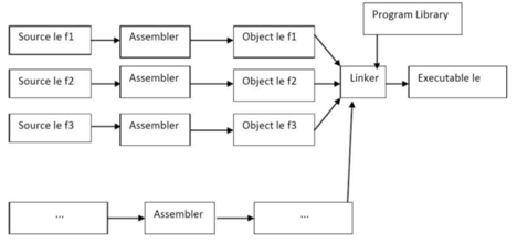
Fig 2: General loader
Key takeaway
In this loader scheme, the source program is converted to object program by some translator (assembler). The loader accepts these object modules and puts machine instruction and data in an executable form at their assigned memory.
Absolute loader is a kind of loader in which relocated object files are created, loader accepts these files and places them at specified locations in the memory. This type of loader is called absolute because no relocation information is needed; rather it is
Obtained from the programmer or assembler. The starting address of every module is known to the programmer, this corresponding starting address is stored in the object file, then task of loader becomes very simple and that is to simply place the executable form of the machine instructions at the locations mentioned in the object File.
In this scheme, the programmer or assembler should have knowledge of memory management. The resolution of external references or linking of different subroutines are the issues which need to be handled by the programmer. The programmer should take care of two things: first thing is specification of starting
Address of each module to be used. If some modification is done in some module then the length of that module may vary.
This causes a change in the starting address of immediate next modules, its then the programmer’s duty to make necessary changes in the starting addresses of respective modules. Second thing is, while branching from one segment to another the absolute starting address of respective module is to be known by the programmer so that such address can be specified at respective JMP instructions.
For example
Line number
1 MAIN START 1000
1 JMP 5000
16 STORE instruction at location 2000
END
1 SUM START 5000
2
20 JMP 2000
21 END
In this example there are two segments, which are interdependent. At line number 1 the assembler directive START specifies the physical starting address that can be used during the execution of the first segment MAIN.
Then at line number 15 the JMP instruction is given which specifies the physical starting address that can be used by the second segment. The assembler creates the object codes for these two segments by considering the stating addresses of these two segments. During the execution, the first segment will be loaded at address 1000 and second segment will be loaded at address 5000 as specified by the programmer. Thus the problem of linking is manually solved by the programmer itself by taking care of the mutually dependent dresses.
As you can notice that the control is correctly transferred to the address 5000 for invoking the other segment, and after that at line number 20 the JMP instruction transfers the control to the location 2000, necessarily at location 2000 the instruction STORE of line number 16 is present. Thus resolution of mutual references and linking is done by the programmer.
The task of assembler is to create the object codes for the above segments and along with the information such as starting address of the memory where actually the object code can be placed at the time of execution. The absolute loader accepts these object modules from assembler and by reading the information about their starting addresses, it will actually place (load) them in the memory at the specified address.
Advantages
- It is easy to implement
- This scheme allows multiple programs in different languages.
- The task of loader becomes simpler as its simply obeys the instruction regarding where to place the object code in memory.
- The process of execution is efficient.
Disadvantages
- The programmer should specify the address in core where the application should be loaded.
- If the program contains many subroutines, the programmer must remember the address of each one.
- Additionally, the programmer must use each absolute address explicitly in the other subroutines in order to maintain subroutine linkage.
- Overlapping
Absolute loader algorithm:
Begin
Read header record
Verify program name and length
Read first TEXT record
While record type !=E
Do begin
{If object code is in character form, convert into internal representation} Move object code to
Specified location in memory
Read the next object program record
End
Jump to address specified in END record end
Key takeaway
Absolute loader is a kind of loader in which relocated object files are created, loader accepts these files and places them at specified locations in the memory.
This type of loader is called absolute because no relocation information is needed; rather it is obtained from the programmer or assembler.
When a single subroutine is altered, relocating loaders was introduced to prevent the need for all subroutines to be reassembled. It also allows you to do the programmer's allocation and linking chores. The Binary Symbolic Subroutine (BSS) loader is an example of moving loaders. Despite the fact that the BSS loader only allows for one common data segment, it does allow for multiple procedure segments. This type of loader's assembler assembles each procedure segment separately and delivers the text and data to relocation and intersegment references.
In this technique, the assembler generates text as an output for each source program. The output text is prefixed with a transfer vector containing addresses, which includes names of the subroutines referenced by the source program. The loader would also receive other information from the assembler, such as the length of the entire program and the length of the transfer vector component.
The text and the transfer vector are loaded into the core after this information is provided. The loader would next load each subroutine that has been identified in the transfer vector. For each entry in the transfer vector, a transfer instruction would be placed in the relevant subroutine.
The object program and information about all the programs to which it refers are the outputs of the relocating assembler. It also includes relocation information for the locations that must be altered before it can be put into the core. This placement in the core could be arbitrary, such as the places that are depending on the core allocation. In computers having a fixed-length direct-address instruction format, the BSS loader technique is most commonly utilized.
Consider the following example of the 360 RX instruction format:

The 16-bit absolute address of the operand is A2 in this format, which is the direct address instruction format. Every instruction should have the address section relocated. As a result, computers with direct-address instruction formats have far more serious issues than computers with 360-type base registers. The problem is solved using relocation bits in 360-type base registers. The assembler associates a bit with each instruction or address field, and the relocation bits are included in the object desk. If the associated bit is one, the corresponding address field for each instruction must be relocated; otherwise, this field is not relocated.
Key takeaway
When a single subroutine is altered, relocating loaders was introduced to prevent the need for all subroutines to be reassembled. It also allows you to do the programmer's allocation and linking chores.
Used Data structures required for designing two pass direct linking loader scheme
Pass 1 database
1. Input object deck
2. A parameter initial program load address(IPLA)
3. A program load address Counter(PLA) used to keep track of each segment assigned location
4. A table the global external symbol table(GEST) that is used to store each external symbol and its corresponding assigned core address.
5. A copy of input later used by pass2
6. A printed Iisting Joad map that specifies each external symbol and its assigned value.
Pass 2 database
1. A copy of object program
2. The initial program load address parameter(IPLA)
3. The program load address Counter(PLA)
4. The global external symbol table prepared by passl
5. An array, the local external symbol array(LESA) which is used to establish a correspondence between ESD ID numbers ,used on ESD and RLD cards, cards and the corresponding external symbol absolute address value.
The following diagram shows two pass direct linking loader scheme
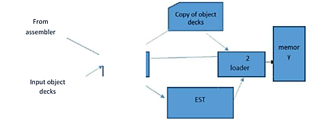
Fig 3: Two pass direct linking loader scheme
Pass I algorithm-allocate segments and define symbols
The purpose of first pass is to assign a location to each segment, and thus to define the values of all external symbols. Since we wish to minimize the amount of core storage required for the total program, we will assign each segment the next available location after the preceding segment. It is necessary for the loader to know where it can load the first segment.
Initially, the PLA is set to initial program load address (IPLA). An object card is then read and a copy written for use by pass2. The card can be one of four types, ESD,TXT,RLD, and END. If it is a TXT or RLD card, there is no processing required during passl so the next card is read. An ESD card is processed in different ways depending upon the type of external symbol, SD,LD. If a segment definition ESD card is read, the length field, LENGTH from the card is temporarily saved in the variable SLENGTH.
The VALUE assigned to this symbol is set to be current value of PLA. The symbol and its assigned value are then stored in the GEST. If the symbol already existed in the GEST then error. The symbol and its value are printed as part of the load map. A similar process is used for LD symbols. The value to be assigned is set to the current PLA plus the relative address ADDR indicated on the ESD card. The ER symbols do not require any processing during pass l. When an END card is encountered, the PLA is incremented by the length of the segment and saved in SLENGTH becoming PLA for the next segment. When an EOF is finally read, pass 1 is completed and control transfer to pass2.
Pass 2 algorithm-load text and relocate /link address constants
After all the segments have been assigned locations and the external symbols have been defined by pass l, it is possible to complete the loading by loading the text and adjusting address constants. At the end of pass2, the loader will transfer control to the loaded program. At the beginning of pass2, initialize IPLA. The cards are read and different types of card are processed accordingly.
Difference between linker and loader
S.no. | LINKER | LOADER |
1 | Linker's primary role is to create executable files. | Loader's primary goal is to load executable files into main memory. |
2 | The linker accepts object code generated by the compiler/assembler as input. | The loader, on the other hand, takes executable files generated by the linker as input. |
3 | Linking is the process of putting together multiple pieces of code and source code to create executable code. | The process of loading executable programmes into main memory for further execution is known as loading. |
4 | There are two sorts of linkers: Linkage Editor and Dynamic Linker. | Absolute, Relocating, Direct Linking, and Bootstrap are the four types of loaders. |
5 | The linker can also be used to assemble all object modules. | It aids in the assignment of addresses to executable codes and files. |
6 | The linker is also in charge of ordering things in the address space of a programme. | The loader is also in charge of modifying references used within the application. |
References:
- Silberschatz, Galvin, Gagne, "Operating System Principles", 9th Edition, Wiley, ISBN 978- 1-118-06333-0
- Alfred V. Aho, Ravi Sethi, Reffrey D. Ullman, “Compilers Principles, Techniques, and Tools”, Addison Wesley, ISBN 981-235-885-4
- Leland Beck, “System Software: An Introduction to Systems Programming”, Pearson
- John Donovan, “Systems Programming”, McGraw Hill, ISBN 978-0--07-460482-3