Unit - 4
Routing
A Router is a process of selecting a path along which the data can be transferred from source to the destination. Routing is performed by a special device known as a router. A Router works at the network layer in the OSI model and internet layer in TCP/IP model A router is a networking device that forwards the packet based on the information available in the packet header and forwarding table.
The routing algorithms are used for routing the packets. The routing algorithm is nothing but a software responsible for deciding the optimal path through which packets can be transmitted. The routing protocols use the metric to determine the best path for the packet delivery. The metric is the standard of measurement such as hop count, bandwidth, delay, current load on the path, etc. used by the routing algorithm to determine the optimal path to the destination. The routing algorithm initializes and maintains the routing table for the process of path determination.
Routing Metrics and Costs
Routing metrics and costs are used for determining the best route to the destination. The factors used by the protocols to determine the shortest path, these factors are known as a metric. Metrics are the network variables used to determine the best route to the destination. For some protocols the static metrics means that their value cannot be changed and for some other routing protocols the dynamic metrics means that their value can be assigned by the system administrator.
The most common metric values are given below:
Hop count: Hop count is defined as a metric that specifies the number of passes through internetworking devices such as a router, a packet must travel in a route to move from source to the destination. If the routing protocol considers the hop as a primary metric value, then the path with the least hop count will be considered as the best path to move from source to the destination.
Delay: It is a time taken by the router to process, queue and transmit a datagram to an interface. The protocols use this metric to determine the delay values for all the links along the path end-to-end. The path having the lowest delay value will be considered as the best path.
Bandwidth: The capacity of the link is known as the bandwidth of the link. The bandwidth is measured in terms of bits per second. The link that has a higher transfer rate like gigabit is preferred over the link that has the lower capacity like 56 kb. The protocol will determine the bandwidth capacity for all the links along the path, and the overall higher bandwidth will be considered as the best route.
Load: Load refers to the degree to which the network resource such as a router or network link is busy. A Load can be calculated in a variety of ways such as CPU utilization, packets processed per second. If the traffic increases, then the load value will also be increased. The load value changes with respect to the change in the traffic.
Reliability: Reliability is a metric factor that may be composed of a fixed value. It depends on the network links, and its value is measured dynamically. Some networks go down more often than others. After network failure, some network links are repaired more easily than other network links. Any reliability factor can be considered for the assignment of reliability ratings, which are generally numeric values assigned by the system administrator.
Types of Routing
Routing can be classified into three categories:
● Static Routing
● Default Routing
● Dynamic Routing
Default Routing
Default Routing is a technique in which a router is configured to send all the packets to the same hop device, and it doesn't matter whether it belongs to a particular network or not. A Packet is transmitted to the device for which it is configured in default routing. Default Routing is used when networks deal with the single exit point. It is also useful when the bulk of transmission networks have to transmit the data to the same hp device. When a specific route is mentioned in the routing table, the router will choose the specific route rather than the default route. The default route is chosen only when a specific route is not mentioned in the routing table.
Key takeaway:
- A Router is a process of selecting a path along which the data can be transferred from source to the destination.
- Routing is performed by a special device known as a router.
- Default Routing is a technique in which a router is configured to send all the packets to the same hop device, and it doesn't matter whether it belongs to a particular network or not.
Static Routing
Static Routing is also known as Non Adaptive Routing. It is a technique in which the administrator manually adds the routes in a routing table. A Router can send the packets for the destination along the route defined by the administrator. In this technique, routing decisions are not made based on the condition or topology of the network.
Advantages of Static Routing
● No Overhead: It has ho overhead on the CPU usage of the router. Therefore, the cheaper router can be used to obtain static routing.
● Bandwidth: It has no bandwidth usage between the routers.
● Security: It provides security as the system administrator is allowed only to have control over the routing to a particular network.
Disadvantages of Static Routing:
● For a large network, it becomes a very difficult task to add each route manually to the routing table. The system administrator should have a good knowledge of a topology as he has to add each route manually.
Dynamic Routing
It is also known as Adaptive Routing. It is a technique in which a router adds a new route in the routing table for each packet in response to the changes in the condition or topology of the network. Dynamic protocols are used to discover the new routes to reach the destination. In Dynamic Routing, RIP and OSPF are the protocols used to discover the new routes. If any route goes down, then the automatic adjustment will be made to reach the destination. The Dynamic protocol should have the following features: All the routers must have the same dynamic routing protocol in order to exchange the routes. If the router discovers any change in the condition or topology, then the router broadcasts this information to all other routers.
Advantages of Dynamic Routing:
● It is easier to configure.
● It is more effective in selecting the best route in response to the changes in the condition or topology.
Disadvantages of Dynamic Routing:
● It is more expensive in terms of CPU and bandwidth usage.
● It is less secure as compared to default and static routing.
The following are some of the key distinctions between static and dynamic routing.
Sr. No. | Key | Static Routing | Dynamic Routing |
1 | Routing pattern | User-defined routes are utilized in the routing table in static routing. | Routes in dynamic routing are modified in response to network changes. |
2 | Routing Algorithm | The shortest path was determined without the use of a sophisticated algorithm. | Complex algorithms are used in dynamic routing to discover the shortest paths. |
3 | Security | The security of static routing is increased. | Dynamic routing is not as safe as static routing. |
4 | Automation | Static routing is a labor-intensive procedure. | Dynamic routing is a fully automated system. |
5 | Applicability | In smaller networks, static routing is employed. | In big networks, dynamic routing is used. |
6 | Protocols | Static routing may or may not adhere to any particular protocol. | BGP, RIP, and EIGRP are examples of dynamic routing protocols. |
7 | Additional Resources | Static routing does not necessitate the allocation of additional resources. | Additional resources, like memory and bandwidth, are required for dynamic routing. |
Key takeaway:
Static Routing is also known as Non Adaptive Routing.
In Dynamic Routing, RIP and OSPF are the protocols used to discover the new routes.
A routing table is a set of rules that determines where data packets going over an Internet Protocol (IP) network will be directed. It is commonly presented in table format. Routing tables are used by all IP-enabled devices, including routers and switches.
A Routing Table is provided below:
Destination Subnet mask Interface
128.75.43.0 255.255.255.0 Eth0
128.75.43.0 255.255.255.128 Eth1
192.12.17.5 255.255.255.255 Eth3
Default Eth2
A network destination of 0.0.0.0 with a network mask (netmask) of 0.0.0.0 corresponds to the default gateway setup. The default route's Subnet Mask is always 255.255.255.255.
Entries of an IP Routing Table:
The information needed to forward a packet along the best path to its destination is stored in a routing table. Each packet is labeled with its origin and destination information. The Routing Table gives the device instructions on how to send the packet to the next hop on its network route.
The following entries make up each entry in the routing table:
● Network ID: The route's related network ID or destination.
● Subnet Mask: The mask that is used to match the network ID to a target IP address.
● Next Hop: The packet is forwarded to this IP address.
● Outgoing Interface: The packet should be sent out the incoming interface to reach the target network.
● Metric: The measure is commonly used to represent the network ID's minimum number of hops (routers crossed).
The following sorts of routes can be stored in routing table entries:
Directly Attached Network IDs
Remote Network IDs
Host Routes
Default Route
Destination
Route Determination Process (finding Subnet ID using Routing Table):
Assume a network is divided into four subnets, as indicated in the diagram above. The IP addresses for the four subnets are as follows:
200.1.2.0 (Subnet a)
200.1.2.64 (Subnet b)
200.1.2.128 (Subnet c)
200.1.2.192 (Subnet d)
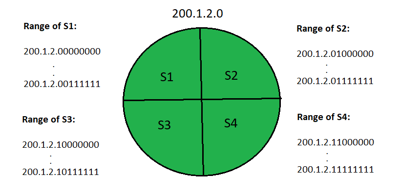
The internal router's routing table then looks like this:
Destination Subnet Mask Interface
200.1.2.0 255.255.255.192 a
200.1.2.64 255.255.255.192 b
200.1.2.128 255.255.255.192 c
200.1.2.192 255.255.255.192 d
Default 0.0.0.0 e
The router performs bitwise ANDing of the destination IP address mentioned on the data packet and all the subnet masks one by one to discover its correct subnet (subnet ID).
● If there is just one match, the data packet is forwarded to the relevant interface by the router.
● If more than one match is found, the data packet is forwarded on the interface with the longest subnet mask.
● If no match is found, the data packet is forwarded on the interface that corresponds to the default entry.
Key takeaway
A routing table is a set of rules that determines where data packets going over an Internet Protocol (IP) network will be directed. It is commonly presented in table format. Routing tables are used by all IP-enabled devices, including routers and switches.
Routing algorithm
● The network layer must find the optimum route through which packets can be transmitted in order to send packets from source to destination.
● The basic job of the network layer, whether it provides datagram service or virtual circuit service, is to provide the optimum path. This is handled by the routing protocol.
● The routing protocol is a routing technique that finds the shortest route from one point to another. The "least-cost path" from source to destination is the optimum way.
● Routing is the process of forwarding packets from a source to a destination, but the routing algorithm determines the optimum route to take.
Shortest path algorithm
In computer networks, shortest path algorithms seek to identify the shortest paths between network nodes in order to reduce routing costs. They are straightforward implementations of graph theory's suggested shortest path algorithms.
Consider a network with N vertices (nodes or network devices) and M edges connecting them (transmission lines). Each edge has a weight connected with it, which represents the transmission line's physical distance or transmission delay. The goal of shortest path algorithms is to discover a path between any two vertices along the edges with the least amount of weights. The shortest path algorithm seeks to discover a route with the fewest number of hops if the edges have equal weights.
It is, in fact, the least-cost path routing, which is optimized via dynamic programming.
The basic idea is to select the cheapest newly reachable node at each step and add an edge to that node to connect it to the tree that has been built up thus far.
Consider a network architecture in which the nodes labeled A through H are routers and each link has a cost.
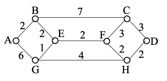
Least-cost path for A → D:
1. B is the cheapest node that can be reached from A, hence it is added to the edge AB.
2. Adds lowest-cost edge B E to E, which is the lowest-cost node reachable from the tree with A and B.
3. Adds lowest-cost edge E g to G, which is the lowest-cost node reachable from the tree with A, B, and E.
4. F is the one with the cheapest edge, E F.
5. H is the one with the least expensive edge F H.
6. Adding the lowest-cost edge H D results in the "shortest" path from A to D: A B E F H D.
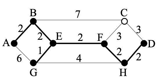
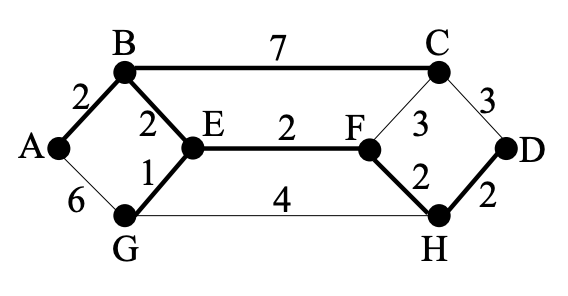
Sink tree with A at root:
We also discover the shortest path from A to G, as well as those to B, E, F, and H, according to the optimality principle. We simply need to discover the shortest path from A to C, which is either A − B − C or A − B − E − F − C., to build the sink tree with A at its root.
Flooding is a simple computer network routing strategy in which a source or node transmits packets over every outbound channel.
Flooding happens when source packets (without routing data) are sent to all associated network nodes, comparable to broadcasting. The shortest path is also employed since flooding uses every path in the network. The flooding algorithm is simple to use.
Data packets do not contain network routing information at first. To track network topology, or traversed network routes, a hop count algorithm is utilised. A packet attempts to access all possible network pathways before arriving at its destination, but packet duplication is always a possibility. To avoid communication delay and duplication, a hop count and various selective flooding techniques are used.
Flooding is also used as a denial of service attack to bring down a network service by flooding network traffic. Many unfinished server connection requests are flooding the service. The server or host is unable to process genuine requests due to the high volume of flooded requests. A flooding attack fills the server or host memory buffer, making it impossible to make new connections, resulting in a denial of service.
Flooding is a non-adaptive routing strategy that works on the following principle: when a data packet arrives at a router, it is delivered to all outgoing lines except the one on which it arrived.
Consider the network shown in the diagram, which consists of six routers connected by transmission lines.
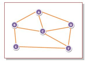
Fig 1: Example
Using flooding technique −
● An incoming packet to A, will be sent to B, C and D.
● B will send the packet to C and E.
● C will send the packet to B, D and F.
● D will send the packet to C and F.
● E will send the packet to F.
● F will send the packet to C and E.
Types of Flooding
There are three forms of flooding.
● Uncontrolled flooding − Each router transmits all incoming data packets to all of its neighbors unconditionally.
● Controlled flooding − They employ a number of techniques to manage packet transport to neighboring nodes. Sequence Number Controlled Flooding (SNCF) and Reverse Path Forwarding are two prominent methods for controlled flooding (RPF).
● Selective flooding − Instead of transmitting incoming packets down all possible paths, the routers only broadcast them along those paths that are headed roughly in the appropriate direction.
Advantages of Flooding
● Because a router may simply know its neighbors, it is incredibly simple to set up and deploy.
● It's highly durable. Even if a high number of routers fail, the packets find a way to get to their destination.
● All nodes that are connected to each other, whether directly or indirectly, are visited. As a result, there is no way for any node to be missed. In the case of broadcast messages, this is an important criterion.
● Flooding always chooses the shortest course.
Limitations of Flooding
● Unless some efforts are taken to damp packet creation, flooding tends to create an unlimited number of duplicate data packets.
● If only one destination requires the packet, it is inefficient since it sends the data packet to all nodes, regardless of the destination.
● Unwanted and duplicate data packets could jam the network. Other data packets may be hampered as a result.
Key takeaway
Flooding is a simple computer network routing strategy in which a source or node transmits packets over every outbound channel.
A distance-vector routing (DVR) protocol is that it requires that a router should inform its neighbors of topology changes takes place periodically. Historically it is known as the old ARPANET routing algorithm (or it is also known as Bellman-Ford algorithm).
Bellman Ford Basics – Each router maintains its Distance Vector table which contains the distance between itself and all possible destination nodes. Distances is based on a chosen metric and are computed using information from the neighbors’ distance vectors.
Example - Consider 3-routers X5 Y and Z as shown in figure. Each router have their routing table. Every routing table will contain distance to the destination nodes.
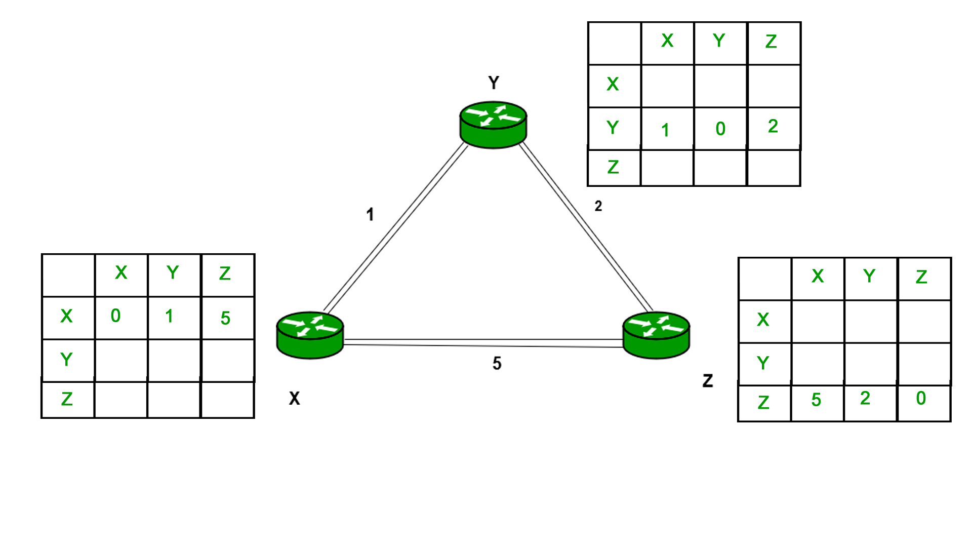
Consider router X 5 X will share it routing table to neighbors and neighbors will share it routing table to it to X and distance from node X to destination will be calculated using bellmen- ford equation.
Dx(y) = min { C(x5v) + Dv(y)} for each node y ∈ N
As we can see that distance will be less going from X to Z when Y is intermediate node (hop) so it will be update in routing table X.
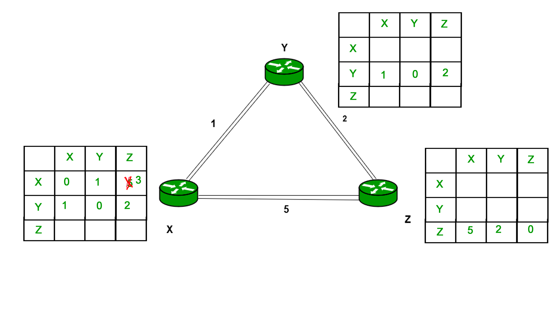
Similarly for Z also –
Finally, the routing table for all is shown above image.
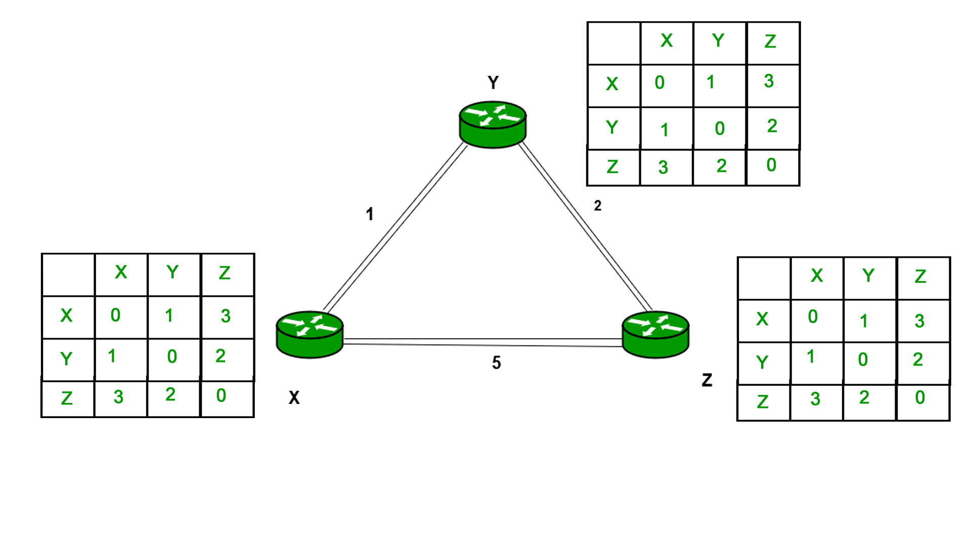
Information which are kept by DV router -
● Each router has its own ID
● IT is associated with each link that are connected to a router,
● There is a cost of the link (static or dynamic).
● Intermediate hops
Distance Vector Table Initialization -
● Distance to itself = 0
● Distance to all other routers = infinity number.
Distance Vector Algorithm –
- A router transmits its distance vector to that of each of its neighbors in that of a routing packet.
- Each router receives and then saves the most recently received distance vector from each of its neighbors.
- A router recalculates its distance vector when the following happens:
○ It receives a distance vector from that of its neighbor containing different information than before.
○ It discovers that a link to a neighbor has slow down.
The DV calculation is based on minimizing the cost to each destination
Dx(y) = Estimate of least cost from x to y
C(x,v) = Node x knows cost to each neighbor v
Dx = [Dx(y): y ∈ N] = Node x maintains distance vector
Node x also maintains its neighbors’ distance vectors
– For each neighbor v, x maintains Dv = [Dv(y): y ∈N ]
Note –
● From time-to-time, each of the node sends its own distance vector which is estimate to its neighbors.
● When a node x receives new DV estimate from any neighbor v, it saves v’s distance vector and it updates its own DV using B-F equation:
● Dx(y) = min { C(x,v) + Dv(y)} for each node y ∈ N
Advantages of Distance Vector routing are as follows –
● It is very simple to configure and it maintains link state routing.
Disadvantages of Distance Vector routing are as follows –
● It is very slow to converge than link state.
● It is at high risk from the count-to-infinity problem.
● It creates more traffic than that of link state since a hop count changes must be propagated to all routers and then processed on each router. Hop count updates take place on periodic basis, even if there are no networks changes in the topology, so bandwidth-wasting broadcasts still occur.
● For the very large networks, distance vector routing results in larger routing tables than link state since each router must know also about all of the other routers. This can also lead to congestion on WAN links.
Note – For UDP (User datagram protocol) transportation it uses Distance Vector routing
Key takeaway
A distance-vector routing (DVR) protocol is that it requires that a router should inform its neighbors of topology changes takes place periodically. Historically it is known as the old ARPANET routing algorithm.
Unicast – Unicast is the transmission from single sender to single receiver. It has point to point communication between the sender end and the receivers end. There are various types of unicast protocols for example TCP, HTTP, etc.
● The most commonly used unicast protocol is TCP. It is a connection oriented protocol that will rely on an acknowledgement from that of the receiver side.
● HTTP is HyperText Transfer Protocol. It is an object oriented protocol for communication.
Three major protocols for unicast routing are:
- Distance Vector Routing
- Link State Routing
- Path-Vector Routing
Link State Routing –
The second family of routing protocols is Link state routing. While the distance vector routers uses a distributed algorithm to compute to their routing tables and link-state routing uses its link-state routers for the exchanging of messages that allows each of the router to learn the entire of the network topology. Based on this learned topology, each router is then will able to compute its own routing table by using a shortest path computation.
Link state routing is a mechanism in which each router in the internetwork communicates its knowledge of its neighborhood with all other routers.
Link state routing protocols features –
● Link state packet – It is a small packet which contains routing information.
● Link state database – It is a collection of information gathered from the link state packet.
● Shortest path first algorithm (Dijkstra algorithm) – The calculation performed on the database which results into the shortest path
● Routing table – It is a list of known paths and interfaces.
Calculation of shortest path –
To find the shortest path, each node needs to run the famous Dijkstra algorithm. Following are the steps of this algorithm:
Step-1: The node is taken and then chosen as a root node of the tree, this will creates the tree with a single node, and now set the total cost of each of the node to some value based on the information in the Link State Database
Step-2: Now the node will select one node, among all of the nodes that is not in the tree like structure, which is nearest to that of the root, and then adds this to the tree. Then the shape of the tree gets changed.
Step-3: After this entire node is added to the tree, then the cost of all the nodes which is not in the tree needs to be updated because of the paths may have been changed.
Step-4: The node repeats the Step 2. And Step 3. Until entire nodes are added in the tree
Link State protocols in comparison to Distance Vector protocols have:
- Large amount of memory is required.
- Many CPU circles are required for shortest path computations.
- If the network uses the small bandwidth then it quickly reacts to changes in the topology.
- All items in the database must be sent to the neighbors to form link state packets.
- All neighbors must be trusted in the topology.
- Authentication mechanisms can be used to avoid undesired adjacency and problems.
- In the link state routing no split horizon techniques are possible.
Advantages:
● This protocol has more information of the inter-network than any other distance vector routing system since it keeps distinct tables for the best and backup routes.
● The concept of triggered updates is used, therefore there is no waste of bandwidth.
● When there is a topology change, partial updates will be triggered, thus the entire routing table will not need to be updated.
Here are some main difference between these Distance Vector and Link State routing protocols:
Distance Vector | Link State |
Distance Vector protocol sends the entire routing table. | Link State protocol sends only link-state information. |
It is susceptible to routing loops. | It is less susceptible to routing loops. |
Updates are sometimes sent using broadcast. | Uses only multicast method for routing updates. |
It is simple to configure. | It is hard to configure this routing protocol. |
Does not know network topology. | Know the entire topology. |
Example RIP, IGRP. | Examples: OSPF IS-IS. |
Key takeaway
Link State protocol sends only link-state information.
Link state routing is a mechanism in which each router in the internetwork communicates its knowledge of its neighborhood with all other routers.
It should come as no surprise that mobile devices pose a number of issues to the Internet's design. The Internet was created in an era when computers were massive, immovable devices, and while the inventors of the Internet were presumably aware that mobile devices will come in the future, it's safe to assume that accommodating them was not a major priority. Mobile computers are ubiquitous today, most notably in the form of laptops and smartphones, but also growing in other forms, such as drones. In this section, we'll look at some of the issues that have arisen as a result of the proliferation of mobile devices, as well as some of the current techniques to dealing with them.
Routing for Mobile
In a wide-area environment, how to relay packets to mobile hosts.
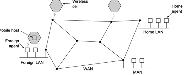
● The mobile host has a fixed residence with a permanent address.
● When a mobile host arrives in a new area, it must register with the local foreign agent.
● The foreign agent can then notify the mobile's home agent, who is located at the mobile's home address, that the mobile is now under its control.
A packet received to a mobile host is forwarded to the mobile's home address.
● The mobile's home agent then tunnels it to the foreign agent where it is now located.
● The home agent also tells the source of the location of the phone.
● The source is able to adapt its routing table thanks to the new address returned by the home agent.
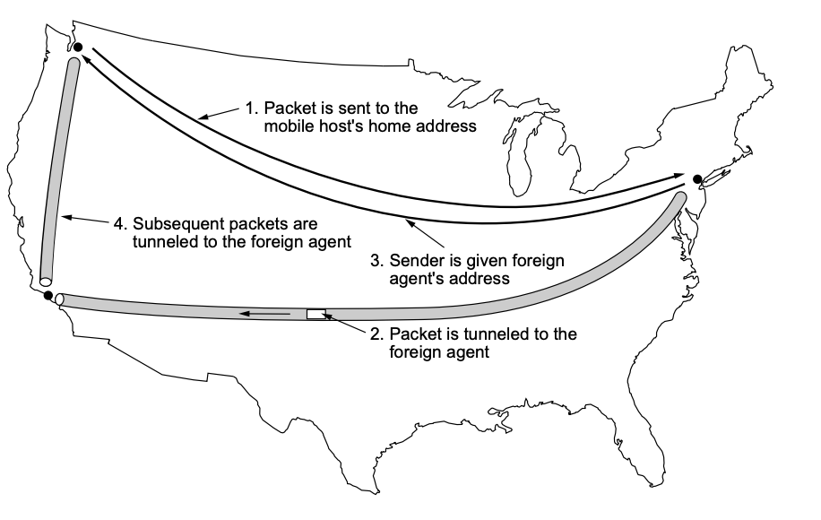
Routing to Mobile Hosts (Mobile IP)
In today's Internet architecture, mobile IP is the major mechanism for addressing the challenge of routing packets to mobile hosts. It adds a few new features while requiring no changes from non-mobile hosts or most routers, allowing for incremental deployment.
The mobile host is believed to have a permanent IP address, which is known as its home address and has the same network prefix as its home network. This is the address that other hosts will use when sending packets to the mobile host; because it does not change, long-lived applications can use it as the host roams. This can be thought of as the host's long-term identify.
When a host travels to a new foreign network that is not its home network, it normally uses DHCP to obtain a new address on that network. This address will vary every time the host roams to a new network, so we may think of it as the host's locator, but it's crucial to remember that the host's permanent home address will not be lost when it gets a new address on the foreign network. While we'll see later, this home address is crucial to its capacity to maintain communications as it moves.
The original Mobile IP standards did not require DHCP because it was established around the same time as Mobile IP, but DHCP is now ubiquitous.
While the majority of routers stay unmodified, mobility support necessitates the addition of additional capabilities in at least one router, referred to as the mobile node's home agent. This router is part of the mobile host's home network. In some circumstances, a foreign agent, a second router with increased capability, is also required. This router is part of a network to which the mobile node connects when it is not connected to its home network. First, we'll look at how Mobile IP works when a foreign agent is employed. An example network with both home and foreign agents is shown in Figure.
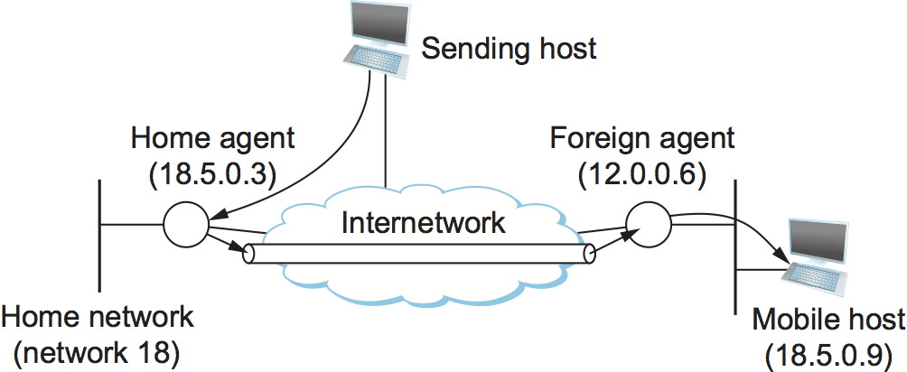
Fig 2: Mobile host and mobility agents
References:
- Behrouz Forouzan, “Data Communication and Networking”, McGraw Hill
- Andrew Tanenbaum “Computer Networks”, Prentice Hall.
- William Stallings, “Data and Computer Communication”, Pearson.
- Kurose and Ross, “Computer Networking- A Top-Down Approach”, Pearson.