Unit - 6
Process to process delivery
Process-to-Process Delivery: The initial task of a transport-layer protocol is to convey data from one process to another. A process is an application layer entity that makes use of the transport layer's services. Between client/server relationships, two processes can be transmitted.
While the Data Link Layer needs the source-destination hosts' MAC addresses (48-bit addresses found within the Network Interface Card of any host machine) to correctly deliver a frame, the Transport Layer requires a Port number to correctly deliver data segments to the correct process among the multiple processes operating on a single host.
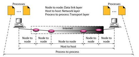
Fig 1: Process to process delivery
Key takeaway
Process-to-Process Delivery: The initial task of a transport-layer protocol is to convey data from one process to another. A process is an application layer entity that makes use of the transport layer's services. Between client/server relationships, two processes can be transmitted.
In computer networking, the UDP stands for User Datagram Protocol. David P. Reed developed the UDP protocol in 1980. It is defined in RFC 768, and it is a part of the TCP/IP protocol, so it is a standard protocol over the internet. The UDP protocol allows the computer applications to send the messages in the form of datagrams from one machine to another machine over the Internet protocol (IP) network.
The UDP is an alternative communication protocol to the TCP protocol (transmission control protocol). Like TCP, UDP provides a set of rules that governs how the data should be exchanged over the internet. The UDP works by encapsulating the data into the packet and providing its own header information to the packet. Then, this UDP packet is encapsulated to the IP packet and sent off to its destination. Both the TCP and UDP protocols send the data over the internet protocol network, so it is also known as TCP/IP and UDP/IP.
There are many differences between these two protocols. UDP enables the process-to-process communication, whereas the TCP provides host to host communication. Since UDP sends the messages in the form of datagrams, it is considered the best-effort mode of communication. TCP sends the individual packets, so it is a reliable transport medium.
Another difference is that the TCP is a connection-oriented protocol whereas the UDP is a connectionless protocol as it does not require any virtual circuit to transfer the data. UDP also provides a different port number to distinguish different user requests and also provides the checksum capability to verify whether the complete data has arrived or not; the IP layer does not provide these two services.
Features of UDP protocol
The following are the features of the UDP protocol:
● Transport layer protocol
UDP is the simplest transport layer communication protocol. It contains a minimum amount of communication mechanisms. It is considered an unreliable protocol, and it is based on best-effort delivery services. UDP provides no acknowledgment mechanism, which means that the receiver does not send the acknowledgment for the received packet, and the sender also does not wait for the acknowledgment for the packet that it has sent.
● Connectionless
The UDP is a connectionless protocol as it does not create a virtual path to transfer the data. It does not use the virtual path, so packets are sent in different paths between the sender and the receiver, which leads to the loss of packets or received out of order.
Ordered delivery of data is not guaranteed.
In the case of UDP, the datagrams sent in some order will be received in the same order is not guaranteed as the datagrams are not numbered.
● Ports
The UDP protocol uses different port numbers so that the data can be sent to the correct destination. The port numbers are defined between 0 and 1023.
● Faster transmission
UDP enables faster transmission as it is a connectionless protocol, i.e., no virtual path is required to transfer the data. But there is a chance that the individual packet is lost, which affects the transmission quality. On the other hand, if the packet is lost in TCP connection, that packet will be resent, so it guarantees the delivery of the data packets.
● Acknowledgment mechanism
The UDP does have an acknowledgment mechanism, i.e., there is no handshaking between the UDP sender and UDP receiver. If the message is sent in TCP, then the receiver acknowledges that I am ready, then the sender sends the data. In the case of TCP, the handshaking occurs between the sender and the receiver, whereas in UDP, there is no handshaking between the sender and the receiver.
● Segments are handled independently.
Each UDP segment is handled individually by others as each segment takes a different path to reach the destination. The UDP segments can be lost or delivered out of order to reach the destination as there is no connection setup between the sender and the receiver.
● Stateless
It is a stateless protocol that means that the sender does not get the acknowledgement for the packet which has been sent.
Why do we require the UDP protocol?
As we know that the UDP is an unreliable protocol, but we still require a UDP protocol in some cases. The UDP is deployed where the packets require a large amount of bandwidth along with the actual data. For example, in video streaming, acknowledging thousands of packets is troublesome and wastes a lot of bandwidth. In the case of video streaming, the loss of some packets couldn't create a problem, and it can also be ignored.
UDP Header Format

Fig 2: UDP header format
In UDP, the header size is 8 bytes, and the packet size is up to 65,535 bytes. But this packet size is not possible as the data needs to be encapsulated in the IP datagram, and an IP packet, the header size can be 20 bytes; therefore, the maximum of UDP would be 65,535 minus 20. The size of the data that the UDP packet can carry would be 65,535 minus 28 as 8 bytes for the header of the UDP packet and 20 bytes for IP header.
The UDP header contains four fields:
● Source port number: It is 16-bit information that identifies which port is going to send the packet.
● Destination port number: It identifies which port is going to accept the information. It is 16-bit information which is used to identify application-level service on the destination machine.
● Length: It is a 16-bit field that specifies the entire length of the UDP packet that includes the header also. The minimum value would be 8-byte as the size of the header is 8 bytes.
● Checksum: It is a 16-bits field, and it is an optional field. This checksum field checks whether the information is accurate or not as there is the possibility that the information can be corrupted while transmission. It is an optional field, which means that it depends upon the application, whether it wants to write the checksum or not. If it does not want to write the checksum, then all the 16 bits are zero; otherwise, it writes the checksum. In UDP, the checksum field is applied to the entire packet, i.e., header as well as data part whereas, in IP, the checksum field is applied to only the header field.
Concept of Queuing in UDP protocol
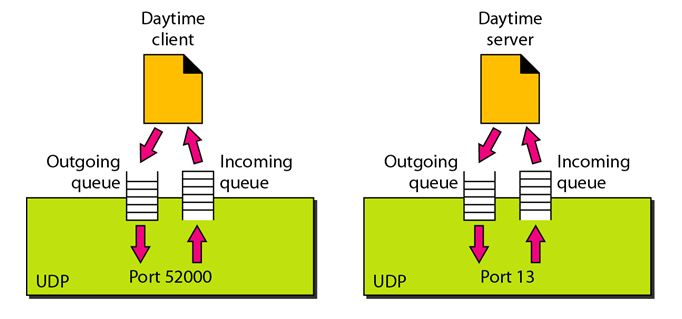
Fig 3: Concept of Queuing in UDP protocol
In UDP protocol, numbers are used to distinguish the different processes on a server and client. We know that UDP provides a process-to-process communication. The client generates the processes that need services while the server generates the processes that provide services. The queues are available for both the processes, i.e., two queues for each process. The first queue is the incoming queue that receives the messages, and the second one is the outgoing queue that sends the messages. The queue functions when the process is running. If the process is terminated then the queue will also get destroyed.
UDP handles the sending and receiving of the UDP packets with the help of the following components:
● Input queue: The UDP packet uses a set of queues for each process.
● Input module: This module takes the user datagram from the IP, and then it finds the information from the control block table of the same port. If it finds the entry in the control block table with the same port as the user datagram, it enqueues the data.
● Control Block Module: It manages the control block table.
● Control Block Table: The control block table contains the entry of open ports.
● Output module: The output module creates and sends the user datagram.
Several processes want to use the services of UDP. The UDP multiplexes and demultiplexes the processes so that the multiple processes can run on a single host.
Limitations
● It provides an unreliable connection delivery service. It does not provide any services of IP except that it provides process-to-process communication.
● The UDP message can be lost, delayed, duplicated, or can be out of order.
● It does not provide a reliable transport delivery service. It does not provide any acknowledgment or flow control mechanism. However, it does provide error control to some extent.
Advantages
● It produces a minimal number of overheads.
Key takeaway
- In computer networking, the UDP stands for User Datagram Protocol. David P. Reed developed the UDP protocol in 1980.
- The UDP is an alternative communication protocol to the TCP protocol (transmission control protocol).
- The UDP works by encapsulating the data into the packet and providing its own header information to the packet.
- UDP also provides a different port number to distinguish different user requests and also provides the checksum capability to verify whether the complete data has arrived or not; the IP layer does not provide these two services.
TCP stands for Transmission Control Protocol. It is a transport layer protocol that facilitates the transmission of packets from source to destination. It is a connection-oriented protocol that means it establishes the connection prior to the communication that occurs between the computing devices in a network. This protocol is used with an IP protocol, so together, they are referred to as a TCP/IP.
The main functionality of the TCP is to take the data from the application layer. Then it divides the data into several packets, provides numbers to these packets, and finally transmits these packets to the destination. The TCP, on the other side, will reassemble the packets and transmit them to the application layer. As we know that TCP is a connection-oriented protocol, so the connection will remain established until the communication is not completed between the sender and the receiver.
Features of TCP protocol
The following are the features of a TCP protocol:
● Transport Layer Protocol
TCP is a transport layer protocol as it is used in transmitting the data from the sender to the receiver.
● Reliable
TCP is a reliable protocol as it follows the flow and error control mechanism. It also supports the acknowledgment mechanism, which checks the state and sound arrival of the data. In the acknowledgment mechanism, the receiver sends either positive or negative acknowledgment to the sender so that the sender can get to know whether the data packet has been received or needs to resend.
● Order of the data is maintained
This protocol ensures that the data reaches the intended receiver in the same order in which it is sent. It orders and numbers each segment so that the TCP layer on the destination side can reassemble them based on their ordering.
● Connection-oriented
It is a connection-oriented service that means the data exchange occurs only after the connection establishment. When the data transfer is completed, then the connection will get terminated.
● Full duplex
It is a full-duplex means that the data can transfer in both directions at the same time.
● Stream-oriented
TCP is a stream-oriented protocol as it allows the sender to send the data in the form of a stream of bytes and also allows the receiver to accept the data in the form of a stream of bytes. TCP creates an environment in which both the sender and receiver are connected by an imaginary tube known as a virtual circuit. This virtual circuit carries the stream of bytes across the internet.
Need of Transport Control Protocol
In the layered architecture of a network model, the whole task is divided into smaller tasks. Each task is assigned to a particular layer that processes the task. In the TCP/IP model, five layers are application layer, transport layer, network layer, data link layer, and physical layer. The transport layer has a critical role in providing end-to-end communication to the direct application processes. It creates 65,000 ports so that the multiple applications can be accessed at the same time. It takes the data from the upper layer, and it divides the data into smaller packets and then transmits them to the network layer.
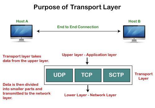
Fig 4: Purpose of transport layer
Working of TCP
In TCP, the connection is established by using three-way handshaking. The client sends the segment with its sequence number. The server, in return, sends its segment with its own sequence number as well as the acknowledgement sequence, which is one more than the client sequence number. When the client receives the acknowledgment of its segment, then it sends the acknowledgment to the server. In this way, the connection is established between the client and the server.
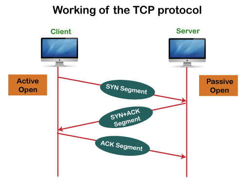
Fig 5: Working of the TCP protocol
Advantages of TCP
● It provides a connection-oriented reliable service, which means that it guarantees the delivery of data packets. If the data packet is lost across the network, then the TCP will resend the lost packets.
● It provides a flow control mechanism using a sliding window protocol.
● It provides error detection by using checksum and error control by using Go Back or ARP protocol.
● It eliminates the congestion by using a network congestion avoidance algorithm that includes various schemes such as additive increase/multiplicative decrease (AIMD), slow start, and congestion window.
Disadvantage of TCP
It increases a large amount of overhead as each segment gets its own TCP header, so fragmentation by the router increases the overhead.
TCP Header format
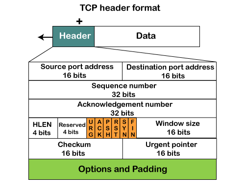
Fig 6: TCP header format
● Source port: It defines the port of the application, which is sending the data. So, this field contains the source port address, which is 16 bits.
● Destination port: It defines the port of the application on the receiving side. So, this field contains the destination port address, which is 16 bits.
● Sequence number: This field contains the sequence number of data bytes in a particular session.
● Acknowledgment number: When the ACK flag is set, then this contains the next sequence number of the data byte and works as an acknowledgment for the previous data received. For example, if the receiver receives the segment number 'x', then it responds 'x+1' as an acknowledgment number.
● HLEN: It specifies the length of the header indicated by the 4-byte words in the header. The size of the header lies between 20 and 60 bytes. Therefore, the value of this field would lie between 5 and 15.
● Reserved: It is a 4-bit field reserved for future use, and by default, all are set to zero.
● Flags
There are six control bits or flags:
- URG: It represents an urgent pointer. If it is set, then the data is processed urgently.
- ACK: If the ACK is set to 0, then it means that the data packet does not contain an acknowledgment.
- PSH: If this field is set, then it requests the receiving device to push the data to the receiving application without buffering it.
- RST: If it is set, then it requests to restart a connection.
- SYN: It is used to establish a connection between the hosts.
- FIN: It is used to release a connection, and no further data exchange will happen.
● Window size
It is a 16-bit field. It contains the size of data that the receiver can accept. This field is used for the flow control between the sender and receiver and also determines the amount of buffer allocated by the receiver for a segment. The value of this field is determined by the receiver.
● Checksum
It is a 16-bit field. This field is optional in UDP, but in the case of TCP/IP, this field is mandatory.
● Urgent pointer
It is a pointer that points to the urgent data byte if the URG flag is set to 1. It defines a value that will be added to the sequence number to get the sequence number of the last urgent byte.
● Options
It provides additional options. The optional field is represented in 32-bits. If this field contains the data less than 32-bit, then padding is required to obtain the remaining bits.
What is a TCP port?
The TCP port is a unique number assigned to different applications. For example, we have opened the email and games applications on our computer; through email application, we want to send the mail to the host, and through games application, we want to play the online games. In order to do all these tasks, different unique numbers are assigned to these applications. Each protocol and address have a port known as a port number. The TCP (Transmission control protocol) and UDP (User Datagram Protocol) protocols mainly use the port numbers.
A port number is a unique identifier used with an IP address. A port is a 16-bit unsigned integer, and the total number of ports available in the TCP/IP model is 65,535 ports. Therefore, the range of port numbers is 0 to 65535. In the case of TCP, the zero-port number is reserved and cannot be used, whereas, in UDP, the zero port is not available. IANA (Internet Assigned Numbers Authority) is a standard body that assigns the port numbers.
Example of port number:
192.168.1.100: 7
In the above case, 192.168.1.100 is an IP address, and 7 is a port number.
To access a particular service, the port number is used with an IP address. The range from 0 to 1023 port numbers are reserved for the standard protocols, and the other port numbers are user-defined.
Why do we require port numbers?
A single client can have multiple connections with the same server or multiple servers. The client may be running multiple applications at the same time. When the client tries to access some service, then the IP address is not sufficient to access the service. To access the service from a server, the port number is required. So, the transport layer plays a major role in providing multiple communication between these applications by assigning a port number to the applications.
Classification of port numbers
The port numbers are divided into three categories:
● Well-known ports
● Registered ports
● Dynamic ports
Well-known ports
The range of well-known ports is 0 to 1023. The well-known ports are used with those protocols that serve common applications and services such as HTTP (Hypertext transfer protocol), IMAP (Internet Message Access Protocol), SMTP (Simple Mail Transfer Protocol), etc. For example, we want to visit some websites on an internet; then, we use http protocol; the http is available with a port number 80, which means that when we use http protocol with an application then it gets port number 80. It is defined that whenever http protocol is used, then port number 80 will be used. Similarly, with other protocols such as SMTP, IMAP, well-known ports are defined. The remaining port numbers are used for random applications.
Registered ports
The range of registered ports is 1024 to 49151. The registered ports are used for the user processes. These processes are individual applications rather than the common applications that have a well-known port.
Dynamic ports
The range of dynamic ports is 49152 to 65535. Another name of the dynamic port is ephemeral ports. These port numbers are assigned to the client application dynamically when a client creates a connection. The dynamic port is identified when the client initiates the connection, whereas the client knows the well-known port prior to the connection. This port is not known to the client when the client connects to the service.
TCP and UDP header
As we know that both TCP and UDP contain source and destination port numbers, and these port numbers are used to identify the application or a server both at the source and the destination side. Both TCP and UDP use port numbers to pass the information to the upper layers.
Let's understand this scenario.
Suppose a client is accessing a web page. The TCP header contains both the source and destination port.
Client-side
Source Port: The source port defines an application to which the TCP segment belongs to, and this port number is dynamically assigned by the client. This is basically a process to which the port number is assigned.
Destination port: The destination port identifies the location of the service on the server so that the server can serve the request of the client.
Server-side
Source port: It defines the application from where the TCP segment came from.
Destination port: It defines the application to which the TCP segment is going to.
In the above case, two processes are used:
Encapsulation: Port numbers are used by the sender to tell the receiver which application it should use for the data.
Decapsulation: Port numbers are used by the receiver to identify which application it should send the data to.
Let's understand the above example by using all three ports, i.e., well-known port, registered port, and dynamic port.
First, we look at a well-known port.
The well-known ports are the ports that serve the common services and applications like http, ftp, smtp, etc. Here, the client uses a well-known port as a destination port while the server uses a well-known port as a source port. For example, the client sends an http request, then, in this case, the destination port would be 80, whereas the http server is serving the request so its source port number would be 80.
Now, we look at the registered port.
The registered port is assigned to the non-common applications. Lots of vendor applications use this port. Like the well-known port, client uses this port as a destination port whereas the server uses this port as a source port.
At the end, we see how dynamic ports work in this scenario.
The dynamic port is the port that is dynamically assigned to the client application when initiating a connection. In this case, the client uses a dynamic port as a source port, whereas the server uses a dynamic port as a destination port. For example, the client sends an http request; then in this case, the destination port would be 80 as it is a http request, and the source port will only be assigned by the client. When the server serves the request, then the source port would be 80 as it is an http server, and the destination port would be the same as the source port of the client. The registered port can also be used in place of a dynamic port.
Let's look at the below example.
Suppose the client is communicating with a server, and sending the http request. So, the client sends the TCP segment to the well-known port, i.e., 80 of the HTTP protocols. In this case, the destination port would be 80 and suppose the source port assigned dynamically by the client is 1028. When the server responds, the destination port is 1028 as the source port defined by the client is 1028, and the source port at the server end would be 80 as the HTTP server is responding to the request of the client.
Key takeaways:
- TCP stands for Transmission Control Protocol. It is a transport layer protocol that facilitates the transmission of packets from source to destination.
- It is a connection-oriented protocol that means it establishes the connection prior to the communication that occurs between the computing devices in a network.
- This protocol is used with an IP protocol, so together, they are referred to as a TCP/IP.
Difference between UDP and TCP
UDP | TCP |
UDP stands for User Datagram Protocol. | TCP stands for Transmission Control Protocol. |
UDP sends the data directly to the destination device. | TCP establishes a connection between the devices before transmitting the data. |
It is a connectionless protocol. | It is a connection-oriented protocol. |
UDP is faster than the TCP protocol. | TCP is slower than the UDP protocol. |
It is an unreliable protocol. | It is a reliable protocol. |
It does not have a sequence number of each byte. | It has a sequence number of each byte. |
QoS is an overall performance measure of the computer network. Quality of Service (QoS) is a group of technologies that work together on a network to ensure that high-priority applications and traffic are reliably delivered even when network capacity is reduced. This is accomplished using QoS technologies, which provide differential handling and power allocation of individual network traffic flows.
Multimedia applications that combine audio, video, and data should be supported by the network. It should be able to do so with enough bandwidth. The delivery timeliness can be extremely critical. Real-time apps are applications that are responsive to data timeliness. The information should be provided in a timely manner. Help quality of service refers to a network that can deliver these various levels of service.
Bandwidth (throughput), latency (delay), jitter (variance in latency), and error rate are all important QoS metrics. As a result, QoS is especially important for high-bandwidth, real-time traffic like VoIP, video conferencing, and video-on-demand, which are sensitive to latency and jitter.
Important flow characteristics of the QoS are given below:
1. Reliability
If a packet gets lost or acknowledgement is not received (at sender), the re-transmission of data will be needed. This decreases the reliability.
The importance of reliability can differ according to the application.
Example: E- mail and file transfer need to have a reliable transmission as compared to that of an audio conferencing.
2. Delay
Delay of a message from source to destination is a very important characteristic. However, delay can be tolerated differently by the different applications.
Example: The time delay cannot be tolerated in audio conferencing (needs a minimum time delay), while the time delay in the email or file transfer has less importance.
3. Jitter
The jitter is the variation in the packet delay.
If the difference between delays is large, then it is called a high jitter. On the contrary, if the difference between delays is small, it is known as low jitter.
Example:
Case1: If 3 packets are sent at times 0, 1, 2 and received at 10, 11, 12. Here, the delay is the same for all packets and it is acceptable for the telephonic conversation.
Case2: If 3 packets 0, 1, 2 are sent and received at 31, 34, 39, so the delay is different for all packets. In this case, the time delay is not acceptable for the telephonic conversation.
4. Bandwidth
Different applications need different bandwidth.
Example: Video conferencing needs more bandwidth in comparison to that of sending an e-mail.
Integrated Services and Differentiated Service
These two models are designed to provide Quality of Service (QoS) in the network.
1. Integrated Services (IntServ)
Integrated service is a flow-based QoS model and designed for IP.
In integrated services, a user needs to create a flow in the network, from source to destination and needs to inform all routers (every router in the system implements IntServ) of the resource requirement.
Following are the steps to understand how integrated services work.
i) Resource Reservation Protocol (RSVP)
An IP is connectionless, datagram, packet-switching protocol. To implement a flow-based model, a signaling protocol is used to run over IP, which provides the signaling mechanism to make reservations (every application needs assurance to make reservation), this protocol is called RSVP.
Ii) Flow Specification
While making reservations, resources need to define the flow specification. The flow specification has two parts:
a) Resource specification
It defines the resources that the flow needs to reserve. For example: Buffer, bandwidth, etc.
b) Traffic specification
It defines the traffic categorization of the flow.
Iii) Admit or deny
After receiving the flow specification from an application, the router decides to admit or deny the service and the decision can be taken based on the previous commitments of the router and current availability of the resource.
Classification of services
The two classes of services to define Integrated Services are:
a) Guaranteed Service Class
This service guarantees that the packets arrive within a specific delivery time and not discarded, if the traffic flow maintains the traffic specification boundary.
This type of service is designed for real time traffic, which needs a guaranty of minimum end to end delay.
Example: Audio conferencing.
b) Controlled Load Service Class
This type of service is designed for the applications, which can accept some delays, but are sensitive to overload networks and to the possibility of losing packets.
Example: E-mail or file transfer.
Problems with Integrated Services
The two problems with the Integrated services are:
i) Scalability
In Integrated Services, it is necessary for each router to keep information of each flow. But this is not always possible due to the growing network.
Ii) Service- Type Limitation
The integrated services model provides only two types of services, guaranteed and control-load.
2. Differentiated Services (DS or Diffserv):
● DS is a computer networking model, which is designed to achieve scalability by managing the network traffic.
● DS is a class based QoS model specially designed for IP.
● DS was designed by IETF (Internet Engineering Task Force) to handle the problems of Integrated Services.
The solutions to handle the problems of Integrated Services are explained below:
1. Scalability
The main processing unit can be moved from the central place to the edge of the network to achieve scalability. The router does not need to store the information about the flows and the applications (or the hosts) define the type of services they want every time while sending the packets.
2. Service Type Limitation
The routers, route the packets on the basis of the class of services defined in the packet and not by the flow. This method is applied by defining the classes based on the requirement of the applications.
Key takeaway:
QoS is an overall performance measure of the computer network.
Bandwidth (throughput), latency (delay), jitter (variance in latency), and error rate are all important QoS metrics.
QoS is especially important for high-bandwidth, real-time traffic like VoIP, video conferencing, and video-on-demand, which are sensitive to latency and jitter.
There are a few ways that can be utilized to improve service quality. Scheduling, traffic shaping, admission control, and resource reservation are the four most frequent strategies.
Scheduling
Different flows of packets arrive at a switch or router for processing. A smart scheduling strategy balances and appropriately distributes the various flows. Several scheduling approaches have been developed to improve service quality. FIFO queuing, priority queuing, and weighted fair queuing are three of them.
i. FIFO Queuing
Packets wait in a buffer (queue) until the node (router or switch) is ready to process them in first-in, first-out (FIFO) queuing. The queue will fill up if the average arrival rate is higher than the average processing rate, and incoming packets will be deleted. A FIFO queue is familiar to those who have had to wait for a bus at a bus stop.

Fig 7: FIFO queue
Ii. Priority Queuing
Packets are first assigned to a priority class in priority queuing. There is a separate queue for each priority class. The highest-priority queue packets are handled first. The lowest-priority queue packets are handled last. It's worth noting that the system doesn't stop serving a queue until it's completely empty. Figure depicts priority queuing with two degrees of priority (for simplicity).
Because higher priority traffic, such as multimedia, can reach its destination with less latency, a priority queue can provide better QoS than a FIFO queue. There is, however, a potential disadvantage. If a high-priority queue has a continuous flow, packets in lower-priority queues will never be processed. This is referred to as starving.
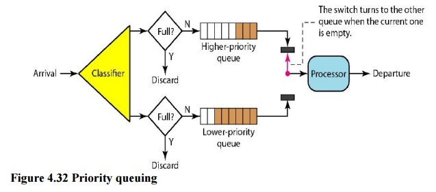
Fig 8: Priority queue
Iii. Weighted Fair Queuing
Weighted fair queuing is a better scheduling strategy. The packets are still assigned to distinct classes and accepted to different queues using this method. The queues, on the other hand, are weighted according to their priority; a higher priority indicates a higher weight. The system processes packets in each queue round-robin, with the number of packets chosen from each queue dependent on its weight. For example, if the weights are 3, 2, and 1, the first queue processes three packets, the second queue two, and the third queue one. All weights can be equal if the system does not assign priority to the classes. As a result, we have fair and prioritized queuing. Figure shows the technique with three classes.
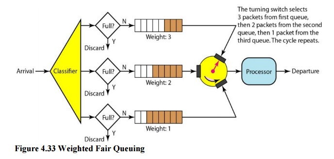
Fig 9: Weighted fair queue
Traffic Shaping
Traffic shaping is a method of controlling the volume and rate of data sent over a network. The leaky bucket and the token bucket are two strategies that can be used to shape traffic.
i. Leaky Bucket
Water leaks from a bucket with a small hole at the bottom at a consistent pace as long as there is water in the bucket. Unless the bucket is empty, the pace at which the water leaks is unrelated to the rate at which the water is added to it. The input rate can change, but the output rate does not. In networking, a technique known as leaky bucket helps smooth out spikes in traffic. Bursty pieces are collected in a bucket and distributed at a steady rate. Figure shows a leaky bucket and its effects.
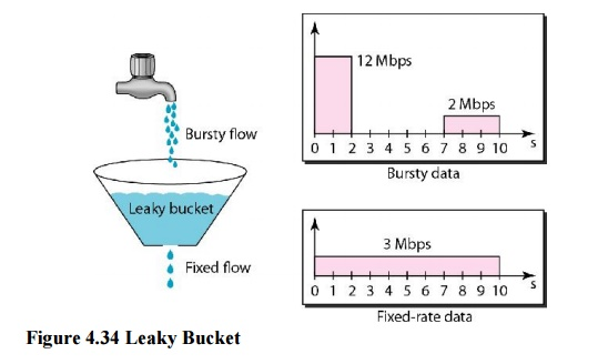
Fig 10: Leaky bucket
In the diagram, we suppose that the network has allocated 3 Mbps of bandwidth to a host. The leaky bucket is used to shape the input traffic so that it adheres to the commitment. In the above example, the host sends a burst of data at 12 Mbps for 2 seconds, totaling 24 Mbits of data. After 5 seconds of silence, the host delivers data at a rate of 2 Mbps for 3 seconds, totaling 6 Mbits of data. The host has sent 30 Mbits of data in lOs in total. The leaky bucket smooths traffic by transmitting data at a 3 Mbps rate over the same 10 seconds.

Fig 11: Leaky bucket implementation
Figure depicts a simple leaky bucket implementation. The packets are stored in a FIFO queue. If the traffic is made up of fixed-size packets (such as cells in ATM networks), the process eliminates a certain number of packets from the queue with each clock tick. If the traffic is made up of packets of varying lengths, the fixed output rate must be determined by the amount of bytes or bits.
Ii. Token Bucket
The leaking bucket is really confining. An idle host is not credited. For example, if a host does not send for an extended period of time, its bucket will become empty. The leaky bucket now only supports an average rate if the host has bursty data. The duration of the host's inactivity is not taken into account. The token bucket method, on the other hand, allows idle hosts to save credit for the future in the form of tokens. The system sends n tokens to the bucket for each tick of the clock. For each cell (or byte) of data sent, the system removes one token. The bucket accumulates 10,000 tokens if n is 100 and the host is idle for 100 ticks.
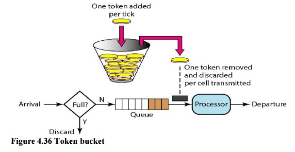
Fig 12: Token bucket
A counter can easily be used to implement the token bucket. The token's value is set to zero. The counter is increased by one each time a token is inserted. The counter is decremented by one each time a unit of data is sent. The host is unable to transfer data when the counter is 0.
Resource Reservation
A data flow necessitates the use of resources such as a buffer, bandwidth, and CPU time, among others. When these resources are booked ahead of time, the quality of service is increased. In this section, we'll look at one QoS model called Integrated Services, which relies significantly on resource reservation to improve service quality.
Admission Control
Admission control is the process by which a router or switch accepts or rejects a flow based on established parameters known as flow requirements. Before accepting a flow for processing, a router examines the flow specifications to verify if the router's capacity (bandwidth, buffer size, CPU speed, and so on) and past commitments to other flows are sufficient to handle the incoming flow.
These are a set of communication standards that allow for the simultaneous digital transmission of voice, video, data, and other network services over traditional PSTN channels. Prior to the introduction of the Integrated Services Digital Network (ISDN), the telephone system was mostly used to transmit voice, with certain data-related services available. The fundamental advantage of ISDN is that it can combine voice and data on the same lines, which is not possible with a traditional telephone system.
ISDN is a circuit-switched telephone network system that also permits access to packet-switched networks for digital speech and data transmission. As a result, speech or data quality may be improved over that of an analogue phone. It provides a packet-switched connection for data at 64 kilobit/s increments. It had a maximum bandwidth of 128 kbit/s in both upstream and downstream directions. Through channel bonding, a higher data rate was attained. ISDN B-channels consisting of three or four BRIs (six to eight 64 kbit/s channels) are typically bonded.
ISDN is used as the network in the data-link and physical layers of the OSI model, but it is typically limited to use with Q.931 and related protocols. These protocols, which were first presented in 1986, are a set of signaling protocols for creating and ending circuit-switched connections, as well as providing advanced user calling capabilities. Between individual desktop videoconferencing systems and group video conferencing systems, ISDN allows for simultaneous audio, video, and text communication.
ISDN is a telephone network-based infrastructure that allows voice and data to be transmitted at high speeds and with higher efficiency at the same time. This is a circuit-switched telephone network that can also connect to packet-switched networks.
The following is a model of a practical ISDN.
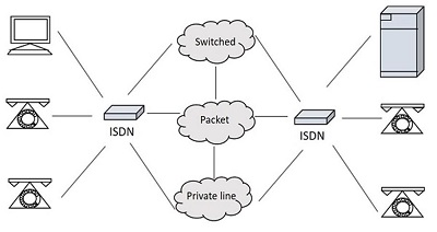
Fig 13: ISDN model
Types of ISDN
Some of the interfaces have channels, such as B-Channels or Bearer Channels, which are used to carry speech and data simultaneously, and D-Channels or Delta Channels, which are used for signaling purposes to establish communication.
The ISDN has a variety of access interfaces, including
Basic Rate Interface (BRI) –
To establish connections, BRI has two data-bearing channels ('B' channels) and one signaling channel ('D' channel). The B channels have a maximum data rate of 64 Kbps, while the D channel has a maximum data rate of 16 Kbps. The two channels are separate from one another. One channel, for example, is used to establish a TCP/IP connection to a place, while the other is utilised to send a fax to a distant location. ISDN has a basic rate interface in the iSeries (BRl).
The basic rate interface (BRl) specifies a digital pipe with two 64-kilobit-per-second B channels and one 16-kilobit-per-second D channel. This corresponds to a data rate of 144 Kbps. Furthermore, the BRl service requires a 48 Kbps operating overhead. As a result, a 192 Kbps digital pipe is required.
Primary Rate Interface (PRI)
Enterprises and offices use the ISDN PRI connection, also known as the Primary Rate Interface or Primary Rate Access. In the United States, Canada, and Japan, the PRI configuration is based on T-carrier or T1, which consists of 23 data or bearer channels and one control or delta channel, each with a 64kbps speed for a bandwidth of 1.544 M bits/sec. In Europe, Australia, and a few Asian nations, the PRI configuration is based on E-carrier or E1, which consists of 30 data or bearer channels and two control or delta channels with 64kbps speeds for a bandwidth of 2.048 M bits/sec.
Larger businesses or enterprises, as well as Internet Service Providers, employ the ISDN BRI interface.
Narrowband ISDN
The N-ISDN stands for Narrowband Integrated Services Digital Network. This is a type of telecommunication that transmits voice data over a restricted spectrum of frequencies. This is a digitalization effort of analogue voice information. Circuit switching at 64kbps is used.
The narrowband ISDN employs a limited number of frequencies to convey voice data, which requires less bandwidth.
Broadband ISDN
The B-ISDN stands for Broadband Integrated Services Digital Network. This combines digital networking services and allows for digital transmission through standard phone lines as well as other media. "Qualifying a service or system that requires transmission channels capable of sustaining rates greater than primary rates," according to the CCITT.
The broadband ISDN speed ranges between 2 MBPS and 1 GBPS, with transmission based on ATM (Asynchronous Transfer Mode). Fiber optic cables are commonly used for broadband ISDN communication.
Broadband Communications are defined as communications at a speed greater than 1.544 megabits per second. Broadband services deliver a constant flow of data from a central source to an unlimited number of authorized receivers linked to the network. Although a user has access to this flow of data, he has no control over it.
ISDN Services:
ISDN offers users a fully integrated digital service. Bearer services, teleservices, and supplemental services are the three types of services available.
Bearer Services –
The bearer network provides information (voice, data, and video) between users without the network modifying the content of that information. The network does not need to process the information, thus it does not affect the content. Bearer services are part of the OSI model's first three levels. The ISDN standard clearly defines them. Circuit-switched, packet-switched, frame-switched, or cell-switched networks can all be used to deliver them.
Teleservices –
The contents of the data may be changed or processed by the network in this way. Layers 4–7 of the OSI model relate to these services. Teleservices are designed to satisfy sophisticated user needs and rely on the bearer services' facilities. The user does not need to be aware of the process's intricacies. Telephony, teletex, telefax, videotex, telex, and teleconferencing are examples of teleservices. Despite the fact that the ISDN names these services, they have not yet become standards.
Supplementary Service –
Supplementary services provide additional functionality to bearer services and teleservices. Reverse billing, call waiting, and message handling are all examples of supplemental services that are common in today's telephone companies.
ATM
Asynchronous transfer mode is abbreviated as ATM. Asynchronous time-division multiplexing is a switching technology used by telecommunication networks to pack data into small, fixed-sized cells. ATMs can be used to move data efficiently across high-speed networks. Real-time and non-real-time services are available at ATMs.
It is a call relay system developed by the International Telecommunication Union's Telecommunications Standards Section (ITU-T). It sends all information, including different service kinds such as data, video, and voice, in small fixed-size packets known as cells. The network is connection-oriented, and cells are broadcast asynchronously.
ATM is a technology that can be regarded as an extension of packet switching and has some roots in the development of broadband ISDN in the 1970s and 1980s. Each cell is 53 bytes long, with a header of 5 bytes and a payload of 48 bytes. To make an ATM call, you must first send a message to establish a connection.
Following that, all cells take the identical route to their destination. It can deal with both constant and variable rate traffic. As a result, it can carry a variety of traffic types while maintaining high quality of service from beginning to end. ATM does not require a transmission channel; it can be sent over a wire or fiber by itself, or it can be bundled into the payload of other carrier systems. With virtual circuits, ATM networks use "packet" or "cell" switching. Its design makes high-performance multimedia networking easier to install.
Services
The following are the services provided by ATM:
● Available Bit Rate: It guarantees a minimum capacity, but when network traffic is minimal, data can be burst to higher capacities.
● Constant Bit Rate: It's used to set a preset bit rate that ensures data is provided in a continuous stream. This is similar to having a leased line.
● Unspecified Bit Rate: This does not guarantee any throughput level and is suitable for applications that can accept delays, such as file sharing.
● Variable Bit Rate (VBR): It can deliver a high throughput, however data is not distributed equally. As a result, it's a popular option for audio and video conferencing.
Features of ATM
● Voice, video, and pictures can all be delivered simultaneously across a single or integrated corporate network, providing flexibility and versatility.
● Increased transmission capacity.
● It aids in the creation of virtual networks.
Digital Subscriber Line (DSL) is the abbreviation for Digital Subscriber Line. DSL is a high-speed internet transmission method that uses a conventional copper wire telephone line. DSL provides the finest value, connectivity, and services when compared to other internet access options such as broadband.
Over a DSL connection, you can transmit data and talk on the phone at the same time. Low frequencies are used to transmit voice signals over the 'voiceband' frequency range (0Hz to 4kHz). While digital communications are sent at high frequencies, analogue signals are not (25kHz to 1.5MHz). DSL filters or splitters are used to ensure that a phone conversation is not disrupted by high frequencies.
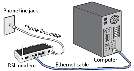
Fig 14: DSL
Types of DSL
● SDSL: Small businesses use symmetric DSL because it provides equal bandwidth for uploading and downloading.
● ADSL: DSL that is asymmetric. The majority of users download more data than they upload, and they utilise ADL to do so. In this case, downstream speed is significantly higher than upstream speed. It's possible that uploading capacity isn't as excellent as downloading capacity. ASDL can be used by users who do not upload as much as they download. It may have a download speed of up to 20 Mbps and an upload speed of 1.5 Mbps.
● HDSL: It's a Digital Subscriber Line with a high bit rate. It's a type of wideband digital transmission that's used both within a firm and between the phone company and its clients. It's a symmetrical line with the same bandwidth each ways.
● RADSL: It's a Rate-Adaptive DSL (rate-adaptive DSL). The modem with this DSL technology may adjust bandwidth and operating speed in order to maximize data throughput. With varying speeds, it offers both symmetrical and asymmetrical applications.
● VDSL: It's a DSL with a very fast data rate. It's a new DSL technology that promises a more stable internet connection than standard broadband. It provides significantly greater data transfer rates over short distances, such as 50 to 55 Mbps across lines up to 300 meters long.
Features
● It's widely accessible.
● It is less expensive and provides more security.
● It is far more dependable than other broadband options.
● It has a slower speed than a broadband connection.
● It has a limited range, thus internet quality suffers as a result of the greater distance between the main hub DSL provider and the receiver.
Key takeaway
‘Digital Subscriber Line (DSL) is the abbreviation for Digital Subscriber Line. DSL is a high-speed internet transmission method that uses a conventional copper wire telephone line. DSL provides the finest value, connectivity, and services when compared to other internet access options such as broadband.
A cable modem is a piece of hardware that connects a computer to an Internet Service Provider (ISP) over a local cable TV line. It features two interfaces: one for connecting to a cable TV network and the other for connecting to a computer, television, or set-top box.
On a cable television (CATV) infrastructure, a Cable Modem offers bi-directional data connection over radio frequency channels. Cable modems are generally used to give broadband Internet access via cable Internet, which takes use of a cable television network's high capacity.
Cable operators have a system in place that allows them to connect a user to one or more operators. As shown in figure, this wiring is made up of the CATV coaxial cable that connects the headend to the users. All branches of the wire broadcast TV channels in the downlink direction. The channels must be superimposed on the tree in the uplink direction.
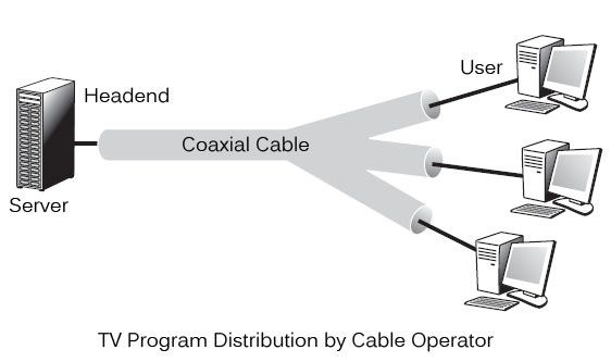
Fig 15: Tv program distribution by cable operator
After a broadcast on all branches, the wiring from a headend to reach the user. Different programmes are pushed to users as part of television broadcasting. Each subscriber is given access to all channels and must choose one to watch. This method is the polar opposite of ADSL, which only routes the user-selected channel.
Configuration
In the beginning, cable modems were proprietary and had to be installed by the cable company. Nowadays, open-standard cable modems are available, which the user can install himself. Data Over Cable Service Interface Spectrum is the name of the standard (DOSCIS). Ethernet or USB are the most common modem-to-computer interfaces. The interface between the modem and the cable network outlet supports FDM, TDM, and CDMA, allowing subscribers to share the cable's bandwidth.
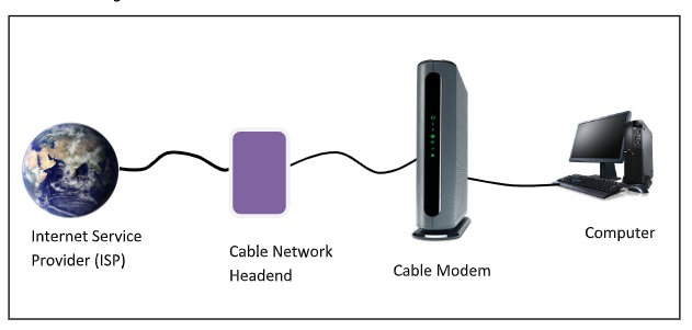
Establishment of Connection
After connecting to the cable TV network, a cable modem examines the downstream channels for a specific packet that is sent over the network on a regular basis. When the modem detects it, it broadcasts its presence across the network. It is assigned for both upstream and downstream communication if its authentication criteria are met.
Channels for Communication
6HMz or 8MHz channels modulated with QAM-64 are utilized for downstream data. This results in a 36Mbps data rate. There is higher radio-frequency noise in upstream data. As a result, the data rate is approximately 9Mbps.
Communication Method
Time division multiplexing (TDM) is used to share upstream data. TDM divides time into mini slots, each of which is allotted to a subscriber who wants to transfer data. A computer transmits data packets to the cable modem when it has data to deliver. The modem asks for how many minislots are required to send the data. If the request is accepted, the modem receives an acknowledgement as well as the number of slots that have been provided. The data packets are subsequently transmitted by the modem in the appropriate order.
Key takeaway
A cable modem is a piece of hardware that connects a computer to an Internet Service Provider (ISP) over a local cable TV line. It features two interfaces: one for connecting to a cable TV network and the other for connecting to a computer, television, or set-top box.
Synchronous Optical Network (SONET) is an acronym for Synchronous Optical Network. SONET is a Bellcore-developed communication protocol for transmitting huge amounts of data over relatively long distances utilizing optical fiber. Multiple digital data streams are sent via the optical fiber at the same time with SONET.
The established protocols synchronous optical networking (SONET) and synchronous digital hierarchy (SDH) use lasers or highly coherent light from light-emitting diodes to transport multiple digital bit streams across optical fiber at the same time (LEDs). At low transmission rates, data can also be sent using an electrical link. The method was developed to replace the plesiochronous digital hierarchy (PDH) system for transporting large amounts of voice and data traffic over a single cable without causing synchronization problems.
SONET and SDH were created to transmit circuit mode communications (e.g., DS1, DS3) from a number of sources, but their primary purpose was to enable real-time, uncompressed, circuit-switched audio encoded in PCM format. The fundamental challenge prior to SONET/SDH was that the synchronization sources for these many circuits were all different. This meant that each circuit had a little different pace and phase than the others. SONET/SDH enables for the simultaneous broadcast of numerous different circuits from various origins within a single framing protocol.
Elements of SONET
● STS Multiplexer − It converts an electrical signal to an optical signal and conducts signal multiplexing.
● STS Demultiplexer − Signal demultiplexing is performed by it. An optical signal is converted into an electrical signal using this device.
● Regenerator − A regenerator is a type of repeater that amplifies an optical signal.
● Add/Drop Multiplexer − You can use this device to merge signals from multiple sources into a single route or to eliminate a signal.

Fig 16: Elements
Layers of SONET
SONET is divided into four layers:
Path Layer −
The Path Layer is in charge of transporting signals from one optical source to another. STS Mux/Demux provides path layer features.
Line Layer −
Signal movement across a physical line is handled by the Line Layer. STS Mux/Demux and Add/Drop Mux both include line layer functionality.
Section Layer −
Signal flow within a physical section is managed by the Section Layer. Each network device provides section layer functions.
Photonic layer −
The physical layer of the OSI model is related to the photonic layer. The physical properties of the optical fibre channel (presence of light = 1 and absence of light = 0) are presented.
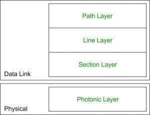
Fig 17: Layer of Sonet
Advantages
● Data is transmitted over long distances.
● There is very little electromagnetic interference.
● Data rates are really high.
● Wide Bandwidth
Key takeaway
Synchronous Optical Network (SONET) is an acronym for Synchronous Optical Network. SONET is a Bellcore-developed communication protocol for transmitting huge amounts of data over relatively long distances utilizing optical fiber.
Wireless LANs are Local Area Networks that connect devices in a LAN using high-frequency radio waves rather than wires. WLAN users are free to move around within the network's service region. The IEEE 802.11 or WiFi standard is used in the majority of WLANs.
Users working in a fixed setting can rely on the wired LAN for reliable service. A wired LAN's workstations and servers are fixed in their native locations once established. Installing a wireless LAN is an excellent alternative for users who are highly mobile or in a harsh terrain where there is no way to install and lay down the cables of a wired LAN.
Wireless LANs use radio frequency (RF) or infrared optical technology to transmit and receive data over the air, obviating the need for fixed cable connections. Wireless LANs provides dual advantage of connectivity and mobility. Wireless LANs have grown in popularity in a variety of industries, including health care, retail, manufacturing, warehousing, and education. Handheld terminals and laptop computers are used in these applications to send real-time data to centralized 'hosts' for processing. Simple wired and wireless networks are depicted in the diagram.
When compared to conventional LANs, wireless LANs have restrictions. Wired LANs are faster than wireless LANs. Also, they have limitations with their range of operation. Due to the poor signal strength, when a station is moved out of its range, it suffers from noise and error in the received data.
IEEE 802.11 Architecture
The following are the components of an IEEE 802.11 architecture:
- Stations (STA) − All devices and equipment linked to the wireless LAN are referred to as stations. There are two types of stations:
● Wireless Access Points (WAP) − WAPs or simply access points (AP) are primarily wireless routers that comprise the base stations or access.
● Client - Workstations, computers, laptops, printers, smartphones, and other devices are examples of clients.
A wireless network interface controller is installed in each station.
2. Basic service set (BSS) - is a group of stations that communicate at the physical layer level. Depending on the manner of operation, BSS can be divided into two categories:
● Infrastructure BSS - The devices communicate with each other through access points in the infrastructure BSS.
● Independent BSS - In this case, the devices communicate ad hoc on a peer-to-peer basis.
3. Extended Service Set (ESS) - is a collection of all BSS that are connected.
4. Distribution System (DS) − It connects access points in ESS.
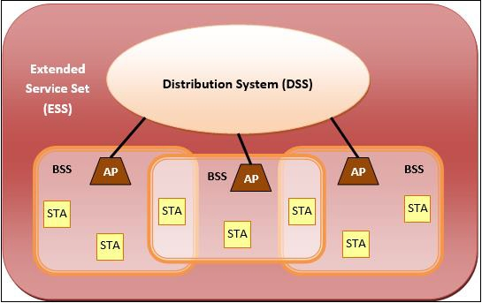
Advantages of WLANs
● They give clutter free homes, offices and other networked spaces.
● The LANs are scalable in nature, i.e. devices may be added or deleted from the network at a higher ease than cable LANs.
● The system is portable within the network's coverage area, and network access is not limited by cable length.
● Installation and setup are far less difficult than with wired counterparts.
● The costs of equipment and setup are lowered.
Disadvantages of WLANs
● Because radio waves are employed for communication, the signals are louder and more susceptible to interference from other systems.
● When it comes to encrypting data, more attention is required. They are also more prone to making mistakes. As a result, they require more bandwidth than cable LANs.
● Wireless LANs (WLANs) are slower than traditional LANs.
Key takeaway
Wireless LANs are Local Area Networks that connect devices in a LAN using high-frequency radio waves rather than wires. WLAN users are free to move around within the network's service region. The IEEE 802.11 or WiFi standard is used in the majority of WLANs.
Bluetooth wireless technology is a short-range communications technology that is designed to replace cables while retaining high levels of security. Bluetooth is based on ad-hoc technology, also known as Ad-hoc Pico nets, which is a local area network with extremely limited coverage.
Bluetooth is a low-power, high-speed wireless technology for connecting phones and other portable devices for conversation and file transmission. This is accomplished through the use of mobile computing technology.
The following is a list of some of Bluetooth's most notable features:
● Bluetooth, also known as the IEEE 802.15 standard or specification, is a wireless technology that connects phones, computers, and other network devices over short distances without the use of wires.
● Because Bluetooth is an open wireless technology standard, it is utilised to send and receive data between connected devices over a short distance using the 2.4 to 2.485 GHz frequency spectrum.
● The wireless signals used in Bluetooth technology carry data and files over a short distance, usually up to 30 feet or 10 meters.
● In 1998, a consortium of five firms called as Special Interest Group developed Bluetooth technology. The companies include Ericsson, Intel, Nokia, IBM, and Toshiba.
● In prior versions of devices, the range of Bluetooth technology for data transmission was up to 10 meters, while the latest version of Bluetooth technology, Bluetooth 5.0, can transmit data over a range of 40-400 meters.
● In the earliest iteration of Bluetooth technology, the typical data transmission speed was roughly 1 Mbps. The second version was 2.0+ EDR, which gave a 3Mbps data rate. The third was 3.0+HS, which offered the speed of 24 Mbps. This technology is currently at version 5.0.
History of Bluetooth
Through a wireless carrier provider, WLAN technology allows devices to connect to infrastructure-based services. Personal Area Networks (PANs) arose from the necessity for personal devices to connect wirelessly with one another in the absence of an established infrastructure (PANs).
● Ericsson's Bluetooth project, which began in 1994, established the standard for PANs, which allows mobile phones to communicate using low-power, low-cost radio interfaces.
● IBM, Intel, Nokia, and Toshiba joined Ericsson to form the Bluetooth Special Interest Group (SIG) in May 1988, with the goal of developing a de facto standard for PANs.
● IEEE has accepted IEEE 802.15.1, a Bluetooth-based standard for Wireless Personal Area Networks (WPANs). MAC and Physical layer applications are covered by the IEEE standard.
● Bluetooth standard defines the whole protocol stack. For communication, Bluetooth uses Radio Frequency (RF). It generates radio waves in the ISM band by using frequency modulation.
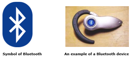
Fig 18: Bluetooth
The Architecture of Bluetooth Technology
● Bluetooth's network comprises of a Personal Area Network (PAN) or a Bluetooth's architecture is also known as a "Piconet" since it is made up of numerous networks in Bluetooth technology.
● A minimum of 2 and a maximum of 8 Bluetooth peer devices are present.
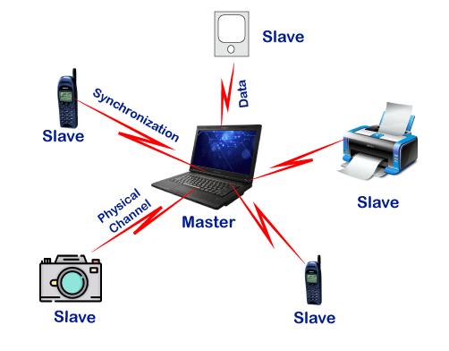
● It normally has one master and up to seven slaves.
● Piconet provides the technology that enables data transfer through its nodes, which include Master and Slave Nodes.
● The master node is in charge of sending data, while the slave nodes are in charge of receiving it.
● Data is sent using Ultra-High Frequency and short-wavelength radio waves in Bluetooth technology.
● Multiplexing and spread spectrum are used in the Piconet. It combines the techniques of code division multiple access (CDMA) and frequency hopping spread spectrum (FHSS).
Working of Bluetooth
A Bluetooth connection can have one master and up to seven slaves, as previously indicated. The device that initiates communication with other devices is known as the master. The master device handles the communications link and traffic between itself and the slave devices associated with it. The slave devices must reply to the master device and synchronise their transmit/receive timing with the time established by the master device.
Advantages
The following are some of the benefits of Bluetooth technology:
● Wireless technology underpins Bluetooth technology. That is why it is inexpensive because no transmission wire is required, lowering the cost.
● In Bluetooth technology, forming a Piconet is quite straightforward.
● It uses the Speed Frequency Hopping technology to solve the problem of radio interference.
● The energy or power usage is extremely low, at around 0.3 milliwatts. It allows for the most efficient use of battery power.
● It is resilient because it ensures bit-level security. A 128-bit encryption key is used for authentication.
● Because Bluetooth can enable data channels of up to three comparable voice channels, you can use it for both data transfer and spoken conversation.
● It does not require line of sight or one-to-one communication, as other wireless communication technologies such as infrared do.
Disadvantages
The following is a list of some of the Bluetooth technology's drawbacks:
● The bandwidth of Bluetooth technology is limited.
● Because the data transfer range is likewise limited, this could be an issue.
Key takeaway
Bluetooth wireless technology is a short-range communications technology that is designed to replace cables while retaining high levels of security. Bluetooth is based on ad-hoc technology, also known as Ad-hoc Pico nets, which is a local area network with extremely limited coverage.
VLAN stands for virtual local area network, and it is made up of one or more local area networks. It allows a set of devices from different networks to be merged into a single logical network. As a result, a virtual LAN that is managed similarly to a physical LAN emerges. VLAN stands for Virtual Local Area Network in its full form.
A network with all hosts inside the same virtual LAN is depicted in the diagram below:
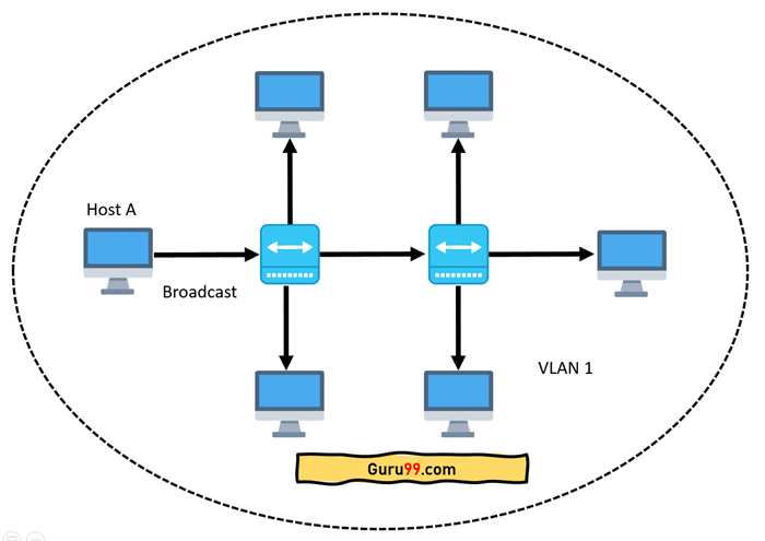
Fig 19: Network having all hosts inside the same VLAN
A broadcast sent from a host can easily reach all network devices without VLANs. Every device will process the broadcast frames it receives. It has the potential to raise CPU burden on each device while lowering overall network security.
If the interfaces on both switches are in different VLANs, a broadcast from host A will only reach devices that are in the same VLAN. VLAN hosts will be completely unaware that communication has occurred. This can be seen in the image below:
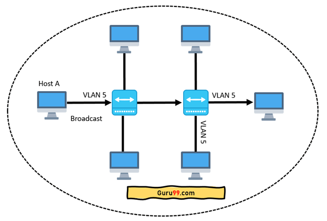
Fig 20: Host A can reach only devices available inside the same VLAN
In networking, a VLAN is a virtual LAN extension. A local area network (LAN) is a collection of computers and peripheral devices connected in a specific area, such as a school, laboratory, home, or business building. It's a popular network for sharing resources such as files, printers, games, and other software.
How VLAN works
The following is a step-by-step explanation of how VLAN works:
● A number is used to identify VLANs in networking.
● 1-4094 is a valid range. You assign the right VLAN number to ports on a VLAN switch.
● The switch then permits data to be transmitted between ports that are part of the same VLAN.
● There should be a means to transport traffic between two switches because practically all networks are larger than a single switch.
● Assigning a VLAN to a port on each network switch and running a cable between them is one simple and easy approach to do this.
Characteristics of VLAN
The following are some of VLAN's most important characteristics:
● Even if their networks are dissimilar, virtual LANs provide structure for forming groups of devices.
● It expands the number of broadcast domains that can be used in a LAN.
● As the number of hosts connected to the broadcast domain drops, implementing VLANs reduces security issues.
● This is accomplished by creating a separate virtual LAN for only the hosts that have sensitive data.
● It uses a flexible networking approach that divides users into departments rather than network locations.
● On a VLAN, changing hosts/users is relatively simple. Only a new port-level setup is required.
● Individual VLANs operate as distinct LANs, which helps to alleviate congestion.
● Each port on a workstation can be used with full bandwidth.
Advantages of VLAN
The following are some of the most prominent advantages and benefits of VLAN:
● It fixes a problem with broadcasting.
● The size of broadcast domains is reduced when using VLAN.
● VLAN allows you to add an extra degree of security to your network.
● It has the potential to make device management much simpler and easier.
● Instead of grouping devices by location, you can group them logically by function.
● It lets you to construct logically connected groups of devices that act as if they're on their own network.
● Departments, project teams, and functions can all be used to logically segment networks.
● VLAN allows you to geographically organize your network in order to support expanding businesses.
● Reduced latency and improved performance.
Disadvantages of VLAN
The following are the major disadvantages and drawbacks of VLAN:
● It is possible for a packet to leak from one VLAN to another.
● A cyber-attack could be launched as a result of an inserted packet.
● A threat in a single system has the potential to transmit a virus throughout an entire logical network.
● In huge networks, you'll need an extra router to keep track of the workload.
● Interoperability issues are possible.
● Network communication cannot be sent from one VLAN to another.
Key takeaway
VLAN stands for virtual local area network, and it is made up of one or more local area networks. It allows a set of devices from different networks to be merged into a single logical network. As a result, a virtual LAN that is managed similarly to a physical LAN emerges. VLAN stands for Virtual Local Area Network in its full form.
Cellular telephony is meant to facilitate communications between two moving units, known as mobile stations (MSs), or between one mobile unit and one immobile stationary unit, sometimes referred to as a land unit.
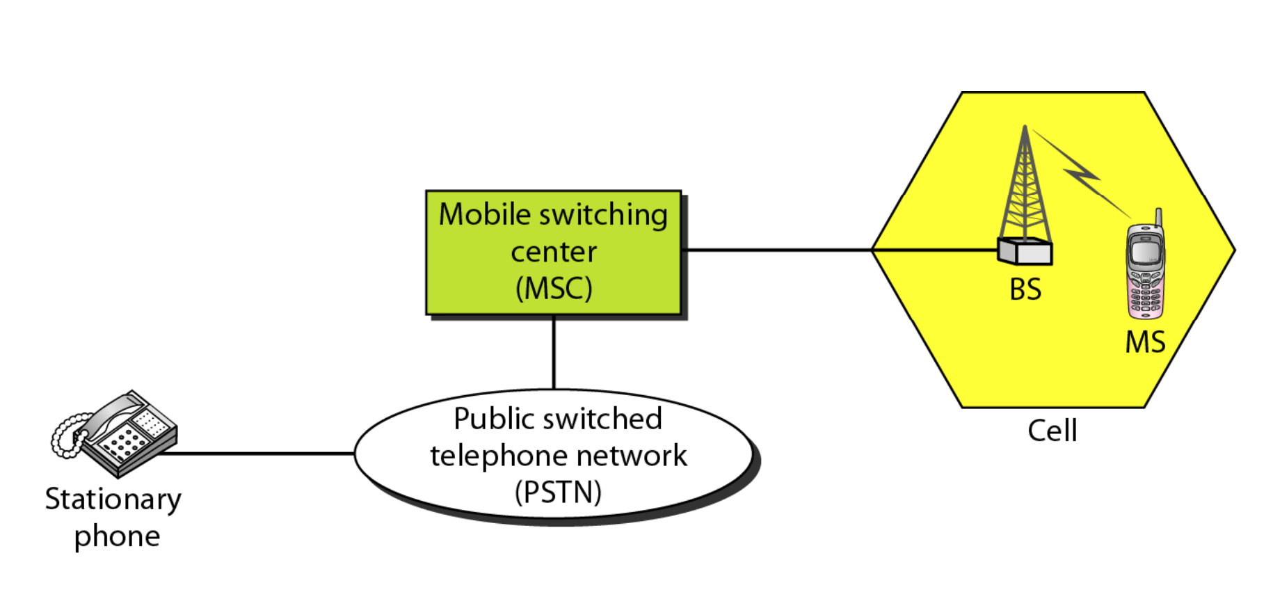
Fig 21: Cellular system
A cellular system consists of the following basic components, as depicted in Figure:
● Mobile Stations (MS): A user's mobile handset is used to communicate with another user.
● Cell: Each cellular service area is divided into cells (5 to 20 kilometers).
● Base Stations (BS): An antenna is located in each cell and is operated by a small office.
● Mobile Switching Center (MSC): A switching office, known as a mobile switching center, is in charge of each base station.
Frequency Reuse Principle
Cellular phone networks rely on channel reuse and efficient channel allocation. Within a cell, each base station is allocated a set of radio channels to use. The channel frequencies given to base stations in neighboring cells are radically different. The same set of channels can be utilized to cover distinct cells separated by a large enough distance to keep interference levels within tolerable bounds by limiting coverage areas, called footprints, within cell boundaries, as shown in Fig.
Reusing cells employ the same set of frequencies as cells with the same letter. Cluster is a collection of N cells that collectively exploit the available frequencies (S = k.N). If a cluster is replicated M times within a system, then total number duplex channels (capacity) is C = M.k.N= M.S.
Reuse factor: Each cell in a cluster is allotted 1/N of the total available channels. Figure 5.9.2 (a) illustrates an example of a reuse factor of 14, whereas Figure (b) inhibits a reuse factor of 1/7.
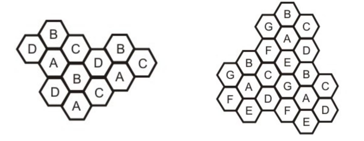
Fig 22: (a) Cells showing reuse factor of ¼, (b) Cells showing reuse factor of 1/7
Transmitting and Receiving
In a cellular telephone network, the basic processes of transmitting and receiving are described.
The following are the steps involved in transmitting:
● A caller pushes the send button after entering a 10-digit code (phone number).
● The MS scans the band for an open channel and sends a powerful signal to transmit the entered number.
● The number is relayed to the MSC by the BS.
● The MSC then sends the request to all of the cellular system's base stations.
● The Mobile Identification Number (MIN) is subsequently transmitted throughout the cellular system via all forward control channels. It's referred to as paging.
● Over the reverse control channel, the MS answers by identifying itself.
● The BS communicates the mobile's acknowledgement and informs the MSC of the handshake.
● The MSC assigns the call to an unused voice channel, and the call is established.
The following are the stages involved in receiving:
● The paging signal is continuously monitored by all idle mobile stations in order to detect messages aimed to them.
● When a call to a mobile station is made, a packet is transmitted to the callee's home MSC to determine its location.
● A packet is transferred to the current cell's base station, which then broadcasts on the paging channel.
● On the control channel, the callee MS answers.
● As a result, a voice channel is assigned, and the MS begins to ring.
Key takeaway
Cellular telephony is meant to facilitate communications between two moving units, known as mobile stations (MSs), or between one mobile unit and one immobile stationary unit, sometimes referred to as a land unit.
A satellite satellite network network is a collection of nodes, some of which are satellites, that allow communication between two points on the Earth. A satellite, satellite, an Earth station, station, or an end user terminal terminal or telephone telephone can all be considered nodes in the network network.
Applications and services of satellite networks
Satellites are artificial stars in the sky that are frequently mistaken for genuine ones. They are mysterious to many people. Scientists and engineers prefer to call them birds because, like birds, they can fly where other organisms can only fantasize. They keep an eye on the earth from above, assist us in navigating the globe, carry our phone calls, emails, and web pages, and relay television programmes across the sky. Satellites, in fact, fly at altitudes much beyond the reach of any real bird. Satellites' high altitude allows them to play a unique role in the global network infrastructure when employed for networking (GNI).
Satellite networking is a rapidly evolving field that has progressed from traditional telephony and television broadcasting to modern broadband and Internet networks and digital satellite broadcasts since the first communications satellite was launched. Satellite networking is at the heart of many technological advancements in networking.
With rising bandwidth and mobility needs on the horizon, satellite is a logical choice for delivering more bandwidth and global coverage beyond the reach of terrestrial networks, and it holds enormous promise for the future. Satellite networks are becoming more and more incorporated into the GNI as networking technologies advance. As a result, satellite networking includes internet-working with terrestrial networks and protocols.
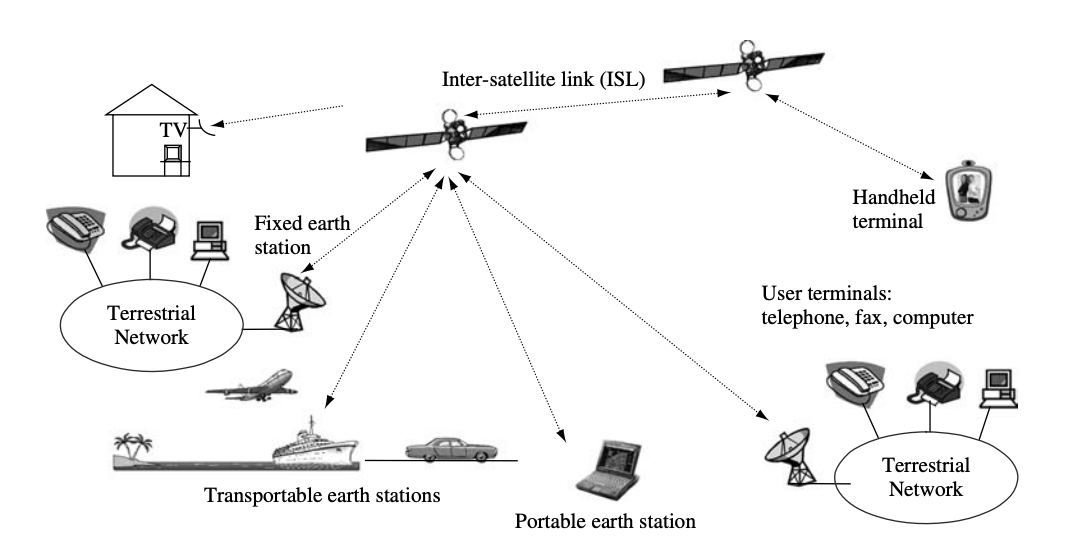
Fig 23: Typical applications and services of satellite networking
Satellite networking's ultimate purpose is to provide services and applications. User terminals give users direct access to services and applications. The network provides transportation services that allow users to send and receive information across a short distance. Figure shows a typical satellite network configuration, which includes terrestrial networks, satellites with an inter-satellite link (ISL), fixed and transportable earth stations, portable and handheld terminals, and user terminals that connect to satellite links directly or via terrestrial networks.
Roles of satellite networks
To reach great distances and cover large areas, terrestrial networks require a large number of links and nodes. They're set up to make network maintenance and operation more cost-effective. In terms of distances, shared bandwidth resources, transmission technologies, design, development, and operation, as well as costs and user needs, satellites are fundamentally different from terrestrial networks.
Satellite networks can provide direct connections between user terminals, terminal-to-terrestrial network connections, and terrestrial-to-terrestrial network connections. People utilize user terminals to access services and applications that are often independent of satellite networks, i.e., the same terminal can access satellite and terrestrial networks.
The earth segment of satellite networks is made up of satellite terminals, also known as earth stations, which provide access to satellite networks for user terminals via the user earth station (UES) and terrestrial networks via the gateway earth station (GES). Satellite networks are built around the satellite, which serves as the hub for both functions and physical connections. The relationship between the user terminal, the terrestrial network, and the satellite network is depicted in the diagram.
Satellite networks are often made up of satellites that connect a few large GES and a lot of tiny UES. The small GES is used for direct user terminal access, whereas the large UES is used to join terrestrial networks. The satellites UES and GES define the satellite network's perimeter. Satellite networks, like other forms of networks, are accessed through the border. The functions of the user terminal and satellite UES are combined in a single device for mobile and transportable terminals, however their antennae are clearly visible for transportable terminals.
The most important roles of satellite networks are to provide access to user terminals and to interconnect with terrestrial networks so that terrestrial networks' applications and services, such as telephony, television, broadband access, and Internet connections, can be extended to places where cable and terrestrial radio cannot be installed and maintained economically. Furthermore, satellite networks may deliver similar services and applications to ships, aircraft, vehicles, space, and other locations where terrestrial networks are unavailable.
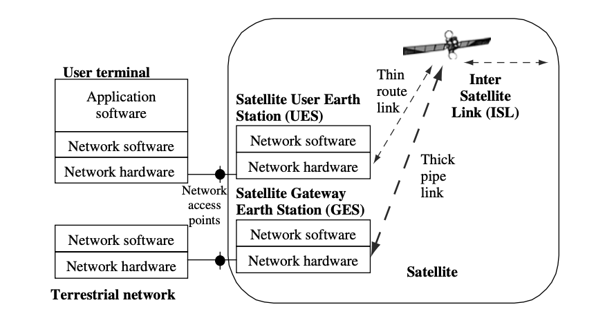
Fig 24: Functional relationships of user terminal, terrestrial network and satellite network
Satellites are also used in the military, meteorology, global positioning systems (GPS), environmental observation, private data and communication services, and the future development of new services and applications for immediate global coverage, such as broadband networks, new generations of mobile networks, and digital broadcast services around the world.
Key takeaway
A satellite satellite network network is a collection of nodes, some of which are satellites, that allow communication between two points on the Earth. A satellite, satellite, an Earth station, station, or an end user terminal terminal or telephone telephone can all be considered nodes in the network network.
References:
- Peterson and Davie, “Computer Networks: A Systems Approach”, Morgan Kaufmann
- W. A. Shay, “Understanding Communications and Networks”, Cengage Learning.
- D. Comer, “Computer Networks and Internets”, Pearson.
- Behrouz Forouzan, “TCP/IP Protocol Suite”, McGraw Hill.
Unit - 6
Process to process delivery
Process-to-Process Delivery: The initial task of a transport-layer protocol is to convey data from one process to another. A process is an application layer entity that makes use of the transport layer's services. Between client/server relationships, two processes can be transmitted.
While the Data Link Layer needs the source-destination hosts' MAC addresses (48-bit addresses found within the Network Interface Card of any host machine) to correctly deliver a frame, the Transport Layer requires a Port number to correctly deliver data segments to the correct process among the multiple processes operating on a single host.
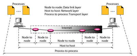
Fig 1: Process to process delivery
Key takeaway
Process-to-Process Delivery: The initial task of a transport-layer protocol is to convey data from one process to another. A process is an application layer entity that makes use of the transport layer's services. Between client/server relationships, two processes can be transmitted.
In computer networking, the UDP stands for User Datagram Protocol. David P. Reed developed the UDP protocol in 1980. It is defined in RFC 768, and it is a part of the TCP/IP protocol, so it is a standard protocol over the internet. The UDP protocol allows the computer applications to send the messages in the form of datagrams from one machine to another machine over the Internet protocol (IP) network.
The UDP is an alternative communication protocol to the TCP protocol (transmission control protocol). Like TCP, UDP provides a set of rules that governs how the data should be exchanged over the internet. The UDP works by encapsulating the data into the packet and providing its own header information to the packet. Then, this UDP packet is encapsulated to the IP packet and sent off to its destination. Both the TCP and UDP protocols send the data over the internet protocol network, so it is also known as TCP/IP and UDP/IP.
There are many differences between these two protocols. UDP enables the process-to-process communication, whereas the TCP provides host to host communication. Since UDP sends the messages in the form of datagrams, it is considered the best-effort mode of communication. TCP sends the individual packets, so it is a reliable transport medium.
Another difference is that the TCP is a connection-oriented protocol whereas the UDP is a connectionless protocol as it does not require any virtual circuit to transfer the data. UDP also provides a different port number to distinguish different user requests and also provides the checksum capability to verify whether the complete data has arrived or not; the IP layer does not provide these two services.
Features of UDP protocol
The following are the features of the UDP protocol:
● Transport layer protocol
UDP is the simplest transport layer communication protocol. It contains a minimum amount of communication mechanisms. It is considered an unreliable protocol, and it is based on best-effort delivery services. UDP provides no acknowledgment mechanism, which means that the receiver does not send the acknowledgment for the received packet, and the sender also does not wait for the acknowledgment for the packet that it has sent.
● Connectionless
The UDP is a connectionless protocol as it does not create a virtual path to transfer the data. It does not use the virtual path, so packets are sent in different paths between the sender and the receiver, which leads to the loss of packets or received out of order.
Ordered delivery of data is not guaranteed.
In the case of UDP, the datagrams sent in some order will be received in the same order is not guaranteed as the datagrams are not numbered.
● Ports
The UDP protocol uses different port numbers so that the data can be sent to the correct destination. The port numbers are defined between 0 and 1023.
● Faster transmission
UDP enables faster transmission as it is a connectionless protocol, i.e., no virtual path is required to transfer the data. But there is a chance that the individual packet is lost, which affects the transmission quality. On the other hand, if the packet is lost in TCP connection, that packet will be resent, so it guarantees the delivery of the data packets.
● Acknowledgment mechanism
The UDP does have an acknowledgment mechanism, i.e., there is no handshaking between the UDP sender and UDP receiver. If the message is sent in TCP, then the receiver acknowledges that I am ready, then the sender sends the data. In the case of TCP, the handshaking occurs between the sender and the receiver, whereas in UDP, there is no handshaking between the sender and the receiver.
● Segments are handled independently.
Each UDP segment is handled individually by others as each segment takes a different path to reach the destination. The UDP segments can be lost or delivered out of order to reach the destination as there is no connection setup between the sender and the receiver.
● Stateless
It is a stateless protocol that means that the sender does not get the acknowledgement for the packet which has been sent.
Why do we require the UDP protocol?
As we know that the UDP is an unreliable protocol, but we still require a UDP protocol in some cases. The UDP is deployed where the packets require a large amount of bandwidth along with the actual data. For example, in video streaming, acknowledging thousands of packets is troublesome and wastes a lot of bandwidth. In the case of video streaming, the loss of some packets couldn't create a problem, and it can also be ignored.
UDP Header Format

Fig 2: UDP header format
In UDP, the header size is 8 bytes, and the packet size is up to 65,535 bytes. But this packet size is not possible as the data needs to be encapsulated in the IP datagram, and an IP packet, the header size can be 20 bytes; therefore, the maximum of UDP would be 65,535 minus 20. The size of the data that the UDP packet can carry would be 65,535 minus 28 as 8 bytes for the header of the UDP packet and 20 bytes for IP header.
The UDP header contains four fields:
● Source port number: It is 16-bit information that identifies which port is going to send the packet.
● Destination port number: It identifies which port is going to accept the information. It is 16-bit information which is used to identify application-level service on the destination machine.
● Length: It is a 16-bit field that specifies the entire length of the UDP packet that includes the header also. The minimum value would be 8-byte as the size of the header is 8 bytes.
● Checksum: It is a 16-bits field, and it is an optional field. This checksum field checks whether the information is accurate or not as there is the possibility that the information can be corrupted while transmission. It is an optional field, which means that it depends upon the application, whether it wants to write the checksum or not. If it does not want to write the checksum, then all the 16 bits are zero; otherwise, it writes the checksum. In UDP, the checksum field is applied to the entire packet, i.e., header as well as data part whereas, in IP, the checksum field is applied to only the header field.
Concept of Queuing in UDP protocol
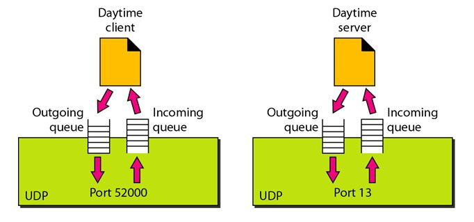
Fig 3: Concept of Queuing in UDP protocol
In UDP protocol, numbers are used to distinguish the different processes on a server and client. We know that UDP provides a process-to-process communication. The client generates the processes that need services while the server generates the processes that provide services. The queues are available for both the processes, i.e., two queues for each process. The first queue is the incoming queue that receives the messages, and the second one is the outgoing queue that sends the messages. The queue functions when the process is running. If the process is terminated then the queue will also get destroyed.
UDP handles the sending and receiving of the UDP packets with the help of the following components:
● Input queue: The UDP packet uses a set of queues for each process.
● Input module: This module takes the user datagram from the IP, and then it finds the information from the control block table of the same port. If it finds the entry in the control block table with the same port as the user datagram, it enqueues the data.
● Control Block Module: It manages the control block table.
● Control Block Table: The control block table contains the entry of open ports.
● Output module: The output module creates and sends the user datagram.
Several processes want to use the services of UDP. The UDP multiplexes and demultiplexes the processes so that the multiple processes can run on a single host.
Limitations
● It provides an unreliable connection delivery service. It does not provide any services of IP except that it provides process-to-process communication.
● The UDP message can be lost, delayed, duplicated, or can be out of order.
● It does not provide a reliable transport delivery service. It does not provide any acknowledgment or flow control mechanism. However, it does provide error control to some extent.
Advantages
● It produces a minimal number of overheads.
Key takeaway
- In computer networking, the UDP stands for User Datagram Protocol. David P. Reed developed the UDP protocol in 1980.
- The UDP is an alternative communication protocol to the TCP protocol (transmission control protocol).
- The UDP works by encapsulating the data into the packet and providing its own header information to the packet.
- UDP also provides a different port number to distinguish different user requests and also provides the checksum capability to verify whether the complete data has arrived or not; the IP layer does not provide these two services.
TCP stands for Transmission Control Protocol. It is a transport layer protocol that facilitates the transmission of packets from source to destination. It is a connection-oriented protocol that means it establishes the connection prior to the communication that occurs between the computing devices in a network. This protocol is used with an IP protocol, so together, they are referred to as a TCP/IP.
The main functionality of the TCP is to take the data from the application layer. Then it divides the data into several packets, provides numbers to these packets, and finally transmits these packets to the destination. The TCP, on the other side, will reassemble the packets and transmit them to the application layer. As we know that TCP is a connection-oriented protocol, so the connection will remain established until the communication is not completed between the sender and the receiver.
Features of TCP protocol
The following are the features of a TCP protocol:
● Transport Layer Protocol
TCP is a transport layer protocol as it is used in transmitting the data from the sender to the receiver.
● Reliable
TCP is a reliable protocol as it follows the flow and error control mechanism. It also supports the acknowledgment mechanism, which checks the state and sound arrival of the data. In the acknowledgment mechanism, the receiver sends either positive or negative acknowledgment to the sender so that the sender can get to know whether the data packet has been received or needs to resend.
● Order of the data is maintained
This protocol ensures that the data reaches the intended receiver in the same order in which it is sent. It orders and numbers each segment so that the TCP layer on the destination side can reassemble them based on their ordering.
● Connection-oriented
It is a connection-oriented service that means the data exchange occurs only after the connection establishment. When the data transfer is completed, then the connection will get terminated.
● Full duplex
It is a full-duplex means that the data can transfer in both directions at the same time.
● Stream-oriented
TCP is a stream-oriented protocol as it allows the sender to send the data in the form of a stream of bytes and also allows the receiver to accept the data in the form of a stream of bytes. TCP creates an environment in which both the sender and receiver are connected by an imaginary tube known as a virtual circuit. This virtual circuit carries the stream of bytes across the internet.
Need of Transport Control Protocol
In the layered architecture of a network model, the whole task is divided into smaller tasks. Each task is assigned to a particular layer that processes the task. In the TCP/IP model, five layers are application layer, transport layer, network layer, data link layer, and physical layer. The transport layer has a critical role in providing end-to-end communication to the direct application processes. It creates 65,000 ports so that the multiple applications can be accessed at the same time. It takes the data from the upper layer, and it divides the data into smaller packets and then transmits them to the network layer.
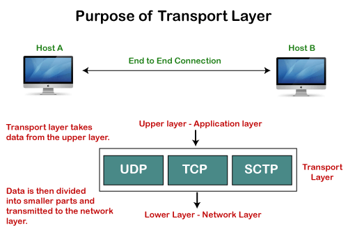
Fig 4: Purpose of transport layer
Working of TCP
In TCP, the connection is established by using three-way handshaking. The client sends the segment with its sequence number. The server, in return, sends its segment with its own sequence number as well as the acknowledgement sequence, which is one more than the client sequence number. When the client receives the acknowledgment of its segment, then it sends the acknowledgment to the server. In this way, the connection is established between the client and the server.
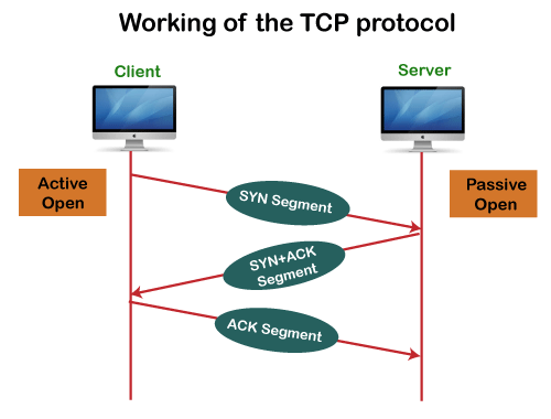
Fig 5: Working of the TCP protocol
Advantages of TCP
● It provides a connection-oriented reliable service, which means that it guarantees the delivery of data packets. If the data packet is lost across the network, then the TCP will resend the lost packets.
● It provides a flow control mechanism using a sliding window protocol.
● It provides error detection by using checksum and error control by using Go Back or ARP protocol.
● It eliminates the congestion by using a network congestion avoidance algorithm that includes various schemes such as additive increase/multiplicative decrease (AIMD), slow start, and congestion window.
Disadvantage of TCP
It increases a large amount of overhead as each segment gets its own TCP header, so fragmentation by the router increases the overhead.
TCP Header format
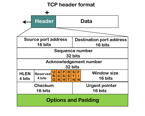
Fig 6: TCP header format
● Source port: It defines the port of the application, which is sending the data. So, this field contains the source port address, which is 16 bits.
● Destination port: It defines the port of the application on the receiving side. So, this field contains the destination port address, which is 16 bits.
● Sequence number: This field contains the sequence number of data bytes in a particular session.
● Acknowledgment number: When the ACK flag is set, then this contains the next sequence number of the data byte and works as an acknowledgment for the previous data received. For example, if the receiver receives the segment number 'x', then it responds 'x+1' as an acknowledgment number.
● HLEN: It specifies the length of the header indicated by the 4-byte words in the header. The size of the header lies between 20 and 60 bytes. Therefore, the value of this field would lie between 5 and 15.
● Reserved: It is a 4-bit field reserved for future use, and by default, all are set to zero.
● Flags
There are six control bits or flags:
- URG: It represents an urgent pointer. If it is set, then the data is processed urgently.
- ACK: If the ACK is set to 0, then it means that the data packet does not contain an acknowledgment.
- PSH: If this field is set, then it requests the receiving device to push the data to the receiving application without buffering it.
- RST: If it is set, then it requests to restart a connection.
- SYN: It is used to establish a connection between the hosts.
- FIN: It is used to release a connection, and no further data exchange will happen.
● Window size
It is a 16-bit field. It contains the size of data that the receiver can accept. This field is used for the flow control between the sender and receiver and also determines the amount of buffer allocated by the receiver for a segment. The value of this field is determined by the receiver.
● Checksum
It is a 16-bit field. This field is optional in UDP, but in the case of TCP/IP, this field is mandatory.
● Urgent pointer
It is a pointer that points to the urgent data byte if the URG flag is set to 1. It defines a value that will be added to the sequence number to get the sequence number of the last urgent byte.
● Options
It provides additional options. The optional field is represented in 32-bits. If this field contains the data less than 32-bit, then padding is required to obtain the remaining bits.
What is a TCP port?
The TCP port is a unique number assigned to different applications. For example, we have opened the email and games applications on our computer; through email application, we want to send the mail to the host, and through games application, we want to play the online games. In order to do all these tasks, different unique numbers are assigned to these applications. Each protocol and address have a port known as a port number. The TCP (Transmission control protocol) and UDP (User Datagram Protocol) protocols mainly use the port numbers.
A port number is a unique identifier used with an IP address. A port is a 16-bit unsigned integer, and the total number of ports available in the TCP/IP model is 65,535 ports. Therefore, the range of port numbers is 0 to 65535. In the case of TCP, the zero-port number is reserved and cannot be used, whereas, in UDP, the zero port is not available. IANA (Internet Assigned Numbers Authority) is a standard body that assigns the port numbers.
Example of port number:
192.168.1.100: 7
In the above case, 192.168.1.100 is an IP address, and 7 is a port number.
To access a particular service, the port number is used with an IP address. The range from 0 to 1023 port numbers are reserved for the standard protocols, and the other port numbers are user-defined.
Why do we require port numbers?
A single client can have multiple connections with the same server or multiple servers. The client may be running multiple applications at the same time. When the client tries to access some service, then the IP address is not sufficient to access the service. To access the service from a server, the port number is required. So, the transport layer plays a major role in providing multiple communication between these applications by assigning a port number to the applications.
Classification of port numbers
The port numbers are divided into three categories:
● Well-known ports
● Registered ports
● Dynamic ports
Well-known ports
The range of well-known ports is 0 to 1023. The well-known ports are used with those protocols that serve common applications and services such as HTTP (Hypertext transfer protocol), IMAP (Internet Message Access Protocol), SMTP (Simple Mail Transfer Protocol), etc. For example, we want to visit some websites on an internet; then, we use http protocol; the http is available with a port number 80, which means that when we use http protocol with an application then it gets port number 80. It is defined that whenever http protocol is used, then port number 80 will be used. Similarly, with other protocols such as SMTP, IMAP, well-known ports are defined. The remaining port numbers are used for random applications.
Registered ports
The range of registered ports is 1024 to 49151. The registered ports are used for the user processes. These processes are individual applications rather than the common applications that have a well-known port.
Dynamic ports
The range of dynamic ports is 49152 to 65535. Another name of the dynamic port is ephemeral ports. These port numbers are assigned to the client application dynamically when a client creates a connection. The dynamic port is identified when the client initiates the connection, whereas the client knows the well-known port prior to the connection. This port is not known to the client when the client connects to the service.
TCP and UDP header
As we know that both TCP and UDP contain source and destination port numbers, and these port numbers are used to identify the application or a server both at the source and the destination side. Both TCP and UDP use port numbers to pass the information to the upper layers.
Let's understand this scenario.
Suppose a client is accessing a web page. The TCP header contains both the source and destination port.
Client-side
Source Port: The source port defines an application to which the TCP segment belongs to, and this port number is dynamically assigned by the client. This is basically a process to which the port number is assigned.
Destination port: The destination port identifies the location of the service on the server so that the server can serve the request of the client.
Server-side
Source port: It defines the application from where the TCP segment came from.
Destination port: It defines the application to which the TCP segment is going to.
In the above case, two processes are used:
Encapsulation: Port numbers are used by the sender to tell the receiver which application it should use for the data.
Decapsulation: Port numbers are used by the receiver to identify which application it should send the data to.
Let's understand the above example by using all three ports, i.e., well-known port, registered port, and dynamic port.
First, we look at a well-known port.
The well-known ports are the ports that serve the common services and applications like http, ftp, smtp, etc. Here, the client uses a well-known port as a destination port while the server uses a well-known port as a source port. For example, the client sends an http request, then, in this case, the destination port would be 80, whereas the http server is serving the request so its source port number would be 80.
Now, we look at the registered port.
The registered port is assigned to the non-common applications. Lots of vendor applications use this port. Like the well-known port, client uses this port as a destination port whereas the server uses this port as a source port.
At the end, we see how dynamic ports work in this scenario.
The dynamic port is the port that is dynamically assigned to the client application when initiating a connection. In this case, the client uses a dynamic port as a source port, whereas the server uses a dynamic port as a destination port. For example, the client sends an http request; then in this case, the destination port would be 80 as it is a http request, and the source port will only be assigned by the client. When the server serves the request, then the source port would be 80 as it is an http server, and the destination port would be the same as the source port of the client. The registered port can also be used in place of a dynamic port.
Let's look at the below example.
Suppose the client is communicating with a server, and sending the http request. So, the client sends the TCP segment to the well-known port, i.e., 80 of the HTTP protocols. In this case, the destination port would be 80 and suppose the source port assigned dynamically by the client is 1028. When the server responds, the destination port is 1028 as the source port defined by the client is 1028, and the source port at the server end would be 80 as the HTTP server is responding to the request of the client.
Key takeaways:
- TCP stands for Transmission Control Protocol. It is a transport layer protocol that facilitates the transmission of packets from source to destination.
- It is a connection-oriented protocol that means it establishes the connection prior to the communication that occurs between the computing devices in a network.
- This protocol is used with an IP protocol, so together, they are referred to as a TCP/IP.
Difference between UDP and TCP
UDP | TCP |
UDP stands for User Datagram Protocol. | TCP stands for Transmission Control Protocol. |
UDP sends the data directly to the destination device. | TCP establishes a connection between the devices before transmitting the data. |
It is a connectionless protocol. | It is a connection-oriented protocol. |
UDP is faster than the TCP protocol. | TCP is slower than the UDP protocol. |
It is an unreliable protocol. | It is a reliable protocol. |
It does not have a sequence number of each byte. | It has a sequence number of each byte. |
QoS is an overall performance measure of the computer network. Quality of Service (QoS) is a group of technologies that work together on a network to ensure that high-priority applications and traffic are reliably delivered even when network capacity is reduced. This is accomplished using QoS technologies, which provide differential handling and power allocation of individual network traffic flows.
Multimedia applications that combine audio, video, and data should be supported by the network. It should be able to do so with enough bandwidth. The delivery timeliness can be extremely critical. Real-time apps are applications that are responsive to data timeliness. The information should be provided in a timely manner. Help quality of service refers to a network that can deliver these various levels of service.
Bandwidth (throughput), latency (delay), jitter (variance in latency), and error rate are all important QoS metrics. As a result, QoS is especially important for high-bandwidth, real-time traffic like VoIP, video conferencing, and video-on-demand, which are sensitive to latency and jitter.
Important flow characteristics of the QoS are given below:
1. Reliability
If a packet gets lost or acknowledgement is not received (at sender), the re-transmission of data will be needed. This decreases the reliability.
The importance of reliability can differ according to the application.
Example: E- mail and file transfer need to have a reliable transmission as compared to that of an audio conferencing.
2. Delay
Delay of a message from source to destination is a very important characteristic. However, delay can be tolerated differently by the different applications.
Example: The time delay cannot be tolerated in audio conferencing (needs a minimum time delay), while the time delay in the email or file transfer has less importance.
3. Jitter
The jitter is the variation in the packet delay.
If the difference between delays is large, then it is called a high jitter. On the contrary, if the difference between delays is small, it is known as low jitter.
Example:
Case1: If 3 packets are sent at times 0, 1, 2 and received at 10, 11, 12. Here, the delay is the same for all packets and it is acceptable for the telephonic conversation.
Case2: If 3 packets 0, 1, 2 are sent and received at 31, 34, 39, so the delay is different for all packets. In this case, the time delay is not acceptable for the telephonic conversation.
4. Bandwidth
Different applications need different bandwidth.
Example: Video conferencing needs more bandwidth in comparison to that of sending an e-mail.
Integrated Services and Differentiated Service
These two models are designed to provide Quality of Service (QoS) in the network.
1. Integrated Services (IntServ)
Integrated service is a flow-based QoS model and designed for IP.
In integrated services, a user needs to create a flow in the network, from source to destination and needs to inform all routers (every router in the system implements IntServ) of the resource requirement.
Following are the steps to understand how integrated services work.
i) Resource Reservation Protocol (RSVP)
An IP is connectionless, datagram, packet-switching protocol. To implement a flow-based model, a signaling protocol is used to run over IP, which provides the signaling mechanism to make reservations (every application needs assurance to make reservation), this protocol is called RSVP.
Ii) Flow Specification
While making reservations, resources need to define the flow specification. The flow specification has two parts:
a) Resource specification
It defines the resources that the flow needs to reserve. For example: Buffer, bandwidth, etc.
b) Traffic specification
It defines the traffic categorization of the flow.
Iii) Admit or deny
After receiving the flow specification from an application, the router decides to admit or deny the service and the decision can be taken based on the previous commitments of the router and current availability of the resource.
Classification of services
The two classes of services to define Integrated Services are:
a) Guaranteed Service Class
This service guarantees that the packets arrive within a specific delivery time and not discarded, if the traffic flow maintains the traffic specification boundary.
This type of service is designed for real time traffic, which needs a guaranty of minimum end to end delay.
Example: Audio conferencing.
b) Controlled Load Service Class
This type of service is designed for the applications, which can accept some delays, but are sensitive to overload networks and to the possibility of losing packets.
Example: E-mail or file transfer.
Problems with Integrated Services
The two problems with the Integrated services are:
i) Scalability
In Integrated Services, it is necessary for each router to keep information of each flow. But this is not always possible due to the growing network.
Ii) Service- Type Limitation
The integrated services model provides only two types of services, guaranteed and control-load.
2. Differentiated Services (DS or Diffserv):
● DS is a computer networking model, which is designed to achieve scalability by managing the network traffic.
● DS is a class based QoS model specially designed for IP.
● DS was designed by IETF (Internet Engineering Task Force) to handle the problems of Integrated Services.
The solutions to handle the problems of Integrated Services are explained below:
1. Scalability
The main processing unit can be moved from the central place to the edge of the network to achieve scalability. The router does not need to store the information about the flows and the applications (or the hosts) define the type of services they want every time while sending the packets.
2. Service Type Limitation
The routers, route the packets on the basis of the class of services defined in the packet and not by the flow. This method is applied by defining the classes based on the requirement of the applications.
Key takeaway:
QoS is an overall performance measure of the computer network.
Bandwidth (throughput), latency (delay), jitter (variance in latency), and error rate are all important QoS metrics.
QoS is especially important for high-bandwidth, real-time traffic like VoIP, video conferencing, and video-on-demand, which are sensitive to latency and jitter.
There are a few ways that can be utilized to improve service quality. Scheduling, traffic shaping, admission control, and resource reservation are the four most frequent strategies.
Scheduling
Different flows of packets arrive at a switch or router for processing. A smart scheduling strategy balances and appropriately distributes the various flows. Several scheduling approaches have been developed to improve service quality. FIFO queuing, priority queuing, and weighted fair queuing are three of them.
i. FIFO Queuing
Packets wait in a buffer (queue) until the node (router or switch) is ready to process them in first-in, first-out (FIFO) queuing. The queue will fill up if the average arrival rate is higher than the average processing rate, and incoming packets will be deleted. A FIFO queue is familiar to those who have had to wait for a bus at a bus stop.

Fig 7: FIFO queue
Ii. Priority Queuing
Packets are first assigned to a priority class in priority queuing. There is a separate queue for each priority class. The highest-priority queue packets are handled first. The lowest-priority queue packets are handled last. It's worth noting that the system doesn't stop serving a queue until it's completely empty. Figure depicts priority queuing with two degrees of priority (for simplicity).
Because higher priority traffic, such as multimedia, can reach its destination with less latency, a priority queue can provide better QoS than a FIFO queue. There is, however, a potential disadvantage. If a high-priority queue has a continuous flow, packets in lower-priority queues will never be processed. This is referred to as starving.
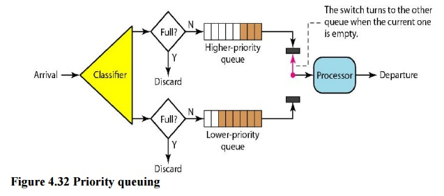
Fig 8: Priority queue
Iii. Weighted Fair Queuing
Weighted fair queuing is a better scheduling strategy. The packets are still assigned to distinct classes and accepted to different queues using this method. The queues, on the other hand, are weighted according to their priority; a higher priority indicates a higher weight. The system processes packets in each queue round-robin, with the number of packets chosen from each queue dependent on its weight. For example, if the weights are 3, 2, and 1, the first queue processes three packets, the second queue two, and the third queue one. All weights can be equal if the system does not assign priority to the classes. As a result, we have fair and prioritized queuing. Figure shows the technique with three classes.
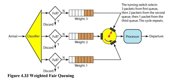
Fig 9: Weighted fair queue
Traffic Shaping
Traffic shaping is a method of controlling the volume and rate of data sent over a network. The leaky bucket and the token bucket are two strategies that can be used to shape traffic.
i. Leaky Bucket
Water leaks from a bucket with a small hole at the bottom at a consistent pace as long as there is water in the bucket. Unless the bucket is empty, the pace at which the water leaks is unrelated to the rate at which the water is added to it. The input rate can change, but the output rate does not. In networking, a technique known as leaky bucket helps smooth out spikes in traffic. Bursty pieces are collected in a bucket and distributed at a steady rate. Figure shows a leaky bucket and its effects.
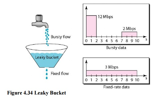
Fig 10: Leaky bucket
In the diagram, we suppose that the network has allocated 3 Mbps of bandwidth to a host. The leaky bucket is used to shape the input traffic so that it adheres to the commitment. In the above example, the host sends a burst of data at 12 Mbps for 2 seconds, totaling 24 Mbits of data. After 5 seconds of silence, the host delivers data at a rate of 2 Mbps for 3 seconds, totaling 6 Mbits of data. The host has sent 30 Mbits of data in lOs in total. The leaky bucket smooths traffic by transmitting data at a 3 Mbps rate over the same 10 seconds.

Fig 11: Leaky bucket implementation
Figure depicts a simple leaky bucket implementation. The packets are stored in a FIFO queue. If the traffic is made up of fixed-size packets (such as cells in ATM networks), the process eliminates a certain number of packets from the queue with each clock tick. If the traffic is made up of packets of varying lengths, the fixed output rate must be determined by the amount of bytes or bits.
Ii. Token Bucket
The leaking bucket is really confining. An idle host is not credited. For example, if a host does not send for an extended period of time, its bucket will become empty. The leaky bucket now only supports an average rate if the host has bursty data. The duration of the host's inactivity is not taken into account. The token bucket method, on the other hand, allows idle hosts to save credit for the future in the form of tokens. The system sends n tokens to the bucket for each tick of the clock. For each cell (or byte) of data sent, the system removes one token. The bucket accumulates 10,000 tokens if n is 100 and the host is idle for 100 ticks.
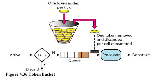
Fig 12: Token bucket
A counter can easily be used to implement the token bucket. The token's value is set to zero. The counter is increased by one each time a token is inserted. The counter is decremented by one each time a unit of data is sent. The host is unable to transfer data when the counter is 0.
Resource Reservation
A data flow necessitates the use of resources such as a buffer, bandwidth, and CPU time, among others. When these resources are booked ahead of time, the quality of service is increased. In this section, we'll look at one QoS model called Integrated Services, which relies significantly on resource reservation to improve service quality.
Admission Control
Admission control is the process by which a router or switch accepts or rejects a flow based on established parameters known as flow requirements. Before accepting a flow for processing, a router examines the flow specifications to verify if the router's capacity (bandwidth, buffer size, CPU speed, and so on) and past commitments to other flows are sufficient to handle the incoming flow.
These are a set of communication standards that allow for the simultaneous digital transmission of voice, video, data, and other network services over traditional PSTN channels. Prior to the introduction of the Integrated Services Digital Network (ISDN), the telephone system was mostly used to transmit voice, with certain data-related services available. The fundamental advantage of ISDN is that it can combine voice and data on the same lines, which is not possible with a traditional telephone system.
ISDN is a circuit-switched telephone network system that also permits access to packet-switched networks for digital speech and data transmission. As a result, speech or data quality may be improved over that of an analogue phone. It provides a packet-switched connection for data at 64 kilobit/s increments. It had a maximum bandwidth of 128 kbit/s in both upstream and downstream directions. Through channel bonding, a higher data rate was attained. ISDN B-channels consisting of three or four BRIs (six to eight 64 kbit/s channels) are typically bonded.
ISDN is used as the network in the data-link and physical layers of the OSI model, but it is typically limited to use with Q.931 and related protocols. These protocols, which were first presented in 1986, are a set of signaling protocols for creating and ending circuit-switched connections, as well as providing advanced user calling capabilities. Between individual desktop videoconferencing systems and group video conferencing systems, ISDN allows for simultaneous audio, video, and text communication.
ISDN is a telephone network-based infrastructure that allows voice and data to be transmitted at high speeds and with higher efficiency at the same time. This is a circuit-switched telephone network that can also connect to packet-switched networks.
The following is a model of a practical ISDN.
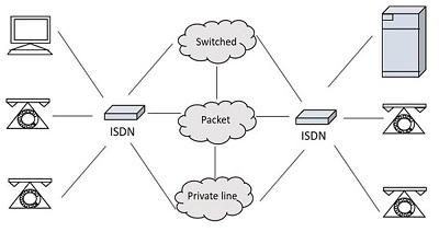
Fig 13: ISDN model
Types of ISDN
Some of the interfaces have channels, such as B-Channels or Bearer Channels, which are used to carry speech and data simultaneously, and D-Channels or Delta Channels, which are used for signaling purposes to establish communication.
The ISDN has a variety of access interfaces, including
Basic Rate Interface (BRI) –
To establish connections, BRI has two data-bearing channels ('B' channels) and one signaling channel ('D' channel). The B channels have a maximum data rate of 64 Kbps, while the D channel has a maximum data rate of 16 Kbps. The two channels are separate from one another. One channel, for example, is used to establish a TCP/IP connection to a place, while the other is utilised to send a fax to a distant location. ISDN has a basic rate interface in the iSeries (BRl).
The basic rate interface (BRl) specifies a digital pipe with two 64-kilobit-per-second B channels and one 16-kilobit-per-second D channel. This corresponds to a data rate of 144 Kbps. Furthermore, the BRl service requires a 48 Kbps operating overhead. As a result, a 192 Kbps digital pipe is required.
Primary Rate Interface (PRI)
Enterprises and offices use the ISDN PRI connection, also known as the Primary Rate Interface or Primary Rate Access. In the United States, Canada, and Japan, the PRI configuration is based on T-carrier or T1, which consists of 23 data or bearer channels and one control or delta channel, each with a 64kbps speed for a bandwidth of 1.544 M bits/sec. In Europe, Australia, and a few Asian nations, the PRI configuration is based on E-carrier or E1, which consists of 30 data or bearer channels and two control or delta channels with 64kbps speeds for a bandwidth of 2.048 M bits/sec.
Larger businesses or enterprises, as well as Internet Service Providers, employ the ISDN BRI interface.
Narrowband ISDN
The N-ISDN stands for Narrowband Integrated Services Digital Network. This is a type of telecommunication that transmits voice data over a restricted spectrum of frequencies. This is a digitalization effort of analogue voice information. Circuit switching at 64kbps is used.
The narrowband ISDN employs a limited number of frequencies to convey voice data, which requires less bandwidth.
Broadband ISDN
The B-ISDN stands for Broadband Integrated Services Digital Network. This combines digital networking services and allows for digital transmission through standard phone lines as well as other media. "Qualifying a service or system that requires transmission channels capable of sustaining rates greater than primary rates," according to the CCITT.
The broadband ISDN speed ranges between 2 MBPS and 1 GBPS, with transmission based on ATM (Asynchronous Transfer Mode). Fiber optic cables are commonly used for broadband ISDN communication.
Broadband Communications are defined as communications at a speed greater than 1.544 megabits per second. Broadband services deliver a constant flow of data from a central source to an unlimited number of authorized receivers linked to the network. Although a user has access to this flow of data, he has no control over it.
ISDN Services:
ISDN offers users a fully integrated digital service. Bearer services, teleservices, and supplemental services are the three types of services available.
Bearer Services –
The bearer network provides information (voice, data, and video) between users without the network modifying the content of that information. The network does not need to process the information, thus it does not affect the content. Bearer services are part of the OSI model's first three levels. The ISDN standard clearly defines them. Circuit-switched, packet-switched, frame-switched, or cell-switched networks can all be used to deliver them.
Teleservices –
The contents of the data may be changed or processed by the network in this way. Layers 4–7 of the OSI model relate to these services. Teleservices are designed to satisfy sophisticated user needs and rely on the bearer services' facilities. The user does not need to be aware of the process's intricacies. Telephony, teletex, telefax, videotex, telex, and teleconferencing are examples of teleservices. Despite the fact that the ISDN names these services, they have not yet become standards.
Supplementary Service –
Supplementary services provide additional functionality to bearer services and teleservices. Reverse billing, call waiting, and message handling are all examples of supplemental services that are common in today's telephone companies.
ATM
Asynchronous transfer mode is abbreviated as ATM. Asynchronous time-division multiplexing is a switching technology used by telecommunication networks to pack data into small, fixed-sized cells. ATMs can be used to move data efficiently across high-speed networks. Real-time and non-real-time services are available at ATMs.
It is a call relay system developed by the International Telecommunication Union's Telecommunications Standards Section (ITU-T). It sends all information, including different service kinds such as data, video, and voice, in small fixed-size packets known as cells. The network is connection-oriented, and cells are broadcast asynchronously.
ATM is a technology that can be regarded as an extension of packet switching and has some roots in the development of broadband ISDN in the 1970s and 1980s. Each cell is 53 bytes long, with a header of 5 bytes and a payload of 48 bytes. To make an ATM call, you must first send a message to establish a connection.
Following that, all cells take the identical route to their destination. It can deal with both constant and variable rate traffic. As a result, it can carry a variety of traffic types while maintaining high quality of service from beginning to end. ATM does not require a transmission channel; it can be sent over a wire or fiber by itself, or it can be bundled into the payload of other carrier systems. With virtual circuits, ATM networks use "packet" or "cell" switching. Its design makes high-performance multimedia networking easier to install.
Services
The following are the services provided by ATM:
● Available Bit Rate: It guarantees a minimum capacity, but when network traffic is minimal, data can be burst to higher capacities.
● Constant Bit Rate: It's used to set a preset bit rate that ensures data is provided in a continuous stream. This is similar to having a leased line.
● Unspecified Bit Rate: This does not guarantee any throughput level and is suitable for applications that can accept delays, such as file sharing.
● Variable Bit Rate (VBR): It can deliver a high throughput, however data is not distributed equally. As a result, it's a popular option for audio and video conferencing.
Features of ATM
● Voice, video, and pictures can all be delivered simultaneously across a single or integrated corporate network, providing flexibility and versatility.
● Increased transmission capacity.
● It aids in the creation of virtual networks.
Digital Subscriber Line (DSL) is the abbreviation for Digital Subscriber Line. DSL is a high-speed internet transmission method that uses a conventional copper wire telephone line. DSL provides the finest value, connectivity, and services when compared to other internet access options such as broadband.
Over a DSL connection, you can transmit data and talk on the phone at the same time. Low frequencies are used to transmit voice signals over the 'voiceband' frequency range (0Hz to 4kHz). While digital communications are sent at high frequencies, analogue signals are not (25kHz to 1.5MHz). DSL filters or splitters are used to ensure that a phone conversation is not disrupted by high frequencies.
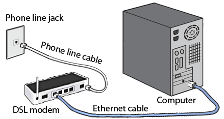
Fig 14: DSL
Types of DSL
● SDSL: Small businesses use symmetric DSL because it provides equal bandwidth for uploading and downloading.
● ADSL: DSL that is asymmetric. The majority of users download more data than they upload, and they utilise ADL to do so. In this case, downstream speed is significantly higher than upstream speed. It's possible that uploading capacity isn't as excellent as downloading capacity. ASDL can be used by users who do not upload as much as they download. It may have a download speed of up to 20 Mbps and an upload speed of 1.5 Mbps.
● HDSL: It's a Digital Subscriber Line with a high bit rate. It's a type of wideband digital transmission that's used both within a firm and between the phone company and its clients. It's a symmetrical line with the same bandwidth each ways.
● RADSL: It's a Rate-Adaptive DSL (rate-adaptive DSL). The modem with this DSL technology may adjust bandwidth and operating speed in order to maximize data throughput. With varying speeds, it offers both symmetrical and asymmetrical applications.
● VDSL: It's a DSL with a very fast data rate. It's a new DSL technology that promises a more stable internet connection than standard broadband. It provides significantly greater data transfer rates over short distances, such as 50 to 55 Mbps across lines up to 300 meters long.
Features
● It's widely accessible.
● It is less expensive and provides more security.
● It is far more dependable than other broadband options.
● It has a slower speed than a broadband connection.
● It has a limited range, thus internet quality suffers as a result of the greater distance between the main hub DSL provider and the receiver.
Key takeaway
‘Digital Subscriber Line (DSL) is the abbreviation for Digital Subscriber Line. DSL is a high-speed internet transmission method that uses a conventional copper wire telephone line. DSL provides the finest value, connectivity, and services when compared to other internet access options such as broadband.
A cable modem is a piece of hardware that connects a computer to an Internet Service Provider (ISP) over a local cable TV line. It features two interfaces: one for connecting to a cable TV network and the other for connecting to a computer, television, or set-top box.
On a cable television (CATV) infrastructure, a Cable Modem offers bi-directional data connection over radio frequency channels. Cable modems are generally used to give broadband Internet access via cable Internet, which takes use of a cable television network's high capacity.
Cable operators have a system in place that allows them to connect a user to one or more operators. As shown in figure, this wiring is made up of the CATV coaxial cable that connects the headend to the users. All branches of the wire broadcast TV channels in the downlink direction. The channels must be superimposed on the tree in the uplink direction.
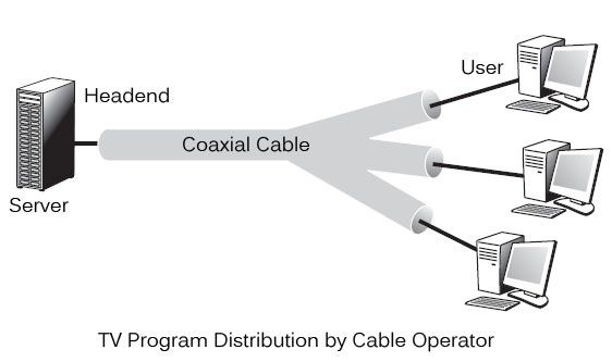
Fig 15: Tv program distribution by cable operator
After a broadcast on all branches, the wiring from a headend to reach the user. Different programmes are pushed to users as part of television broadcasting. Each subscriber is given access to all channels and must choose one to watch. This method is the polar opposite of ADSL, which only routes the user-selected channel.
Configuration
In the beginning, cable modems were proprietary and had to be installed by the cable company. Nowadays, open-standard cable modems are available, which the user can install himself. Data Over Cable Service Interface Spectrum is the name of the standard (DOSCIS). Ethernet or USB are the most common modem-to-computer interfaces. The interface between the modem and the cable network outlet supports FDM, TDM, and CDMA, allowing subscribers to share the cable's bandwidth.
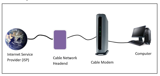
Establishment of Connection
After connecting to the cable TV network, a cable modem examines the downstream channels for a specific packet that is sent over the network on a regular basis. When the modem detects it, it broadcasts its presence across the network. It is assigned for both upstream and downstream communication if its authentication criteria are met.
Channels for Communication
6HMz or 8MHz channels modulated with QAM-64 are utilized for downstream data. This results in a 36Mbps data rate. There is higher radio-frequency noise in upstream data. As a result, the data rate is approximately 9Mbps.
Communication Method
Time division multiplexing (TDM) is used to share upstream data. TDM divides time into mini slots, each of which is allotted to a subscriber who wants to transfer data. A computer transmits data packets to the cable modem when it has data to deliver. The modem asks for how many minislots are required to send the data. If the request is accepted, the modem receives an acknowledgement as well as the number of slots that have been provided. The data packets are subsequently transmitted by the modem in the appropriate order.
Key takeaway
A cable modem is a piece of hardware that connects a computer to an Internet Service Provider (ISP) over a local cable TV line. It features two interfaces: one for connecting to a cable TV network and the other for connecting to a computer, television, or set-top box.
Synchronous Optical Network (SONET) is an acronym for Synchronous Optical Network. SONET is a Bellcore-developed communication protocol for transmitting huge amounts of data over relatively long distances utilizing optical fiber. Multiple digital data streams are sent via the optical fiber at the same time with SONET.
The established protocols synchronous optical networking (SONET) and synchronous digital hierarchy (SDH) use lasers or highly coherent light from light-emitting diodes to transport multiple digital bit streams across optical fiber at the same time (LEDs). At low transmission rates, data can also be sent using an electrical link. The method was developed to replace the plesiochronous digital hierarchy (PDH) system for transporting large amounts of voice and data traffic over a single cable without causing synchronization problems.
SONET and SDH were created to transmit circuit mode communications (e.g., DS1, DS3) from a number of sources, but their primary purpose was to enable real-time, uncompressed, circuit-switched audio encoded in PCM format. The fundamental challenge prior to SONET/SDH was that the synchronization sources for these many circuits were all different. This meant that each circuit had a little different pace and phase than the others. SONET/SDH enables for the simultaneous broadcast of numerous different circuits from various origins within a single framing protocol.
Elements of SONET
● STS Multiplexer − It converts an electrical signal to an optical signal and conducts signal multiplexing.
● STS Demultiplexer − Signal demultiplexing is performed by it. An optical signal is converted into an electrical signal using this device.
● Regenerator − A regenerator is a type of repeater that amplifies an optical signal.
● Add/Drop Multiplexer − You can use this device to merge signals from multiple sources into a single route or to eliminate a signal.

Fig 16: Elements
Layers of SONET
SONET is divided into four layers:
Path Layer −
The Path Layer is in charge of transporting signals from one optical source to another. STS Mux/Demux provides path layer features.
Line Layer −
Signal movement across a physical line is handled by the Line Layer. STS Mux/Demux and Add/Drop Mux both include line layer functionality.
Section Layer −
Signal flow within a physical section is managed by the Section Layer. Each network device provides section layer functions.
Photonic layer −
The physical layer of the OSI model is related to the photonic layer. The physical properties of the optical fibre channel (presence of light = 1 and absence of light = 0) are presented.
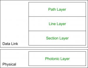
Fig 17: Layer of Sonet
Advantages
● Data is transmitted over long distances.
● There is very little electromagnetic interference.
● Data rates are really high.
● Wide Bandwidth
Key takeaway
Synchronous Optical Network (SONET) is an acronym for Synchronous Optical Network. SONET is a Bellcore-developed communication protocol for transmitting huge amounts of data over relatively long distances utilizing optical fiber.
Wireless LANs are Local Area Networks that connect devices in a LAN using high-frequency radio waves rather than wires. WLAN users are free to move around within the network's service region. The IEEE 802.11 or WiFi standard is used in the majority of WLANs.
Users working in a fixed setting can rely on the wired LAN for reliable service. A wired LAN's workstations and servers are fixed in their native locations once established. Installing a wireless LAN is an excellent alternative for users who are highly mobile or in a harsh terrain where there is no way to install and lay down the cables of a wired LAN.
Wireless LANs use radio frequency (RF) or infrared optical technology to transmit and receive data over the air, obviating the need for fixed cable connections. Wireless LANs provides dual advantage of connectivity and mobility. Wireless LANs have grown in popularity in a variety of industries, including health care, retail, manufacturing, warehousing, and education. Handheld terminals and laptop computers are used in these applications to send real-time data to centralized 'hosts' for processing. Simple wired and wireless networks are depicted in the diagram.
When compared to conventional LANs, wireless LANs have restrictions. Wired LANs are faster than wireless LANs. Also, they have limitations with their range of operation. Due to the poor signal strength, when a station is moved out of its range, it suffers from noise and error in the received data.
IEEE 802.11 Architecture
The following are the components of an IEEE 802.11 architecture:
- Stations (STA) − All devices and equipment linked to the wireless LAN are referred to as stations. There are two types of stations:
● Wireless Access Points (WAP) − WAPs or simply access points (AP) are primarily wireless routers that comprise the base stations or access.
● Client - Workstations, computers, laptops, printers, smartphones, and other devices are examples of clients.
A wireless network interface controller is installed in each station.
2. Basic service set (BSS) - is a group of stations that communicate at the physical layer level. Depending on the manner of operation, BSS can be divided into two categories:
● Infrastructure BSS - The devices communicate with each other through access points in the infrastructure BSS.
● Independent BSS - In this case, the devices communicate ad hoc on a peer-to-peer basis.
3. Extended Service Set (ESS) - is a collection of all BSS that are connected.
4. Distribution System (DS) − It connects access points in ESS.
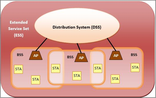
Advantages of WLANs
● They give clutter free homes, offices and other networked spaces.
● The LANs are scalable in nature, i.e. devices may be added or deleted from the network at a higher ease than cable LANs.
● The system is portable within the network's coverage area, and network access is not limited by cable length.
● Installation and setup are far less difficult than with wired counterparts.
● The costs of equipment and setup are lowered.
Disadvantages of WLANs
● Because radio waves are employed for communication, the signals are louder and more susceptible to interference from other systems.
● When it comes to encrypting data, more attention is required. They are also more prone to making mistakes. As a result, they require more bandwidth than cable LANs.
● Wireless LANs (WLANs) are slower than traditional LANs.
Key takeaway
Wireless LANs are Local Area Networks that connect devices in a LAN using high-frequency radio waves rather than wires. WLAN users are free to move around within the network's service region. The IEEE 802.11 or WiFi standard is used in the majority of WLANs.
Bluetooth wireless technology is a short-range communications technology that is designed to replace cables while retaining high levels of security. Bluetooth is based on ad-hoc technology, also known as Ad-hoc Pico nets, which is a local area network with extremely limited coverage.
Bluetooth is a low-power, high-speed wireless technology for connecting phones and other portable devices for conversation and file transmission. This is accomplished through the use of mobile computing technology.
The following is a list of some of Bluetooth's most notable features:
● Bluetooth, also known as the IEEE 802.15 standard or specification, is a wireless technology that connects phones, computers, and other network devices over short distances without the use of wires.
● Because Bluetooth is an open wireless technology standard, it is utilised to send and receive data between connected devices over a short distance using the 2.4 to 2.485 GHz frequency spectrum.
● The wireless signals used in Bluetooth technology carry data and files over a short distance, usually up to 30 feet or 10 meters.
● In 1998, a consortium of five firms called as Special Interest Group developed Bluetooth technology. The companies include Ericsson, Intel, Nokia, IBM, and Toshiba.
● In prior versions of devices, the range of Bluetooth technology for data transmission was up to 10 meters, while the latest version of Bluetooth technology, Bluetooth 5.0, can transmit data over a range of 40-400 meters.
● In the earliest iteration of Bluetooth technology, the typical data transmission speed was roughly 1 Mbps. The second version was 2.0+ EDR, which gave a 3Mbps data rate. The third was 3.0+HS, which offered the speed of 24 Mbps. This technology is currently at version 5.0.
History of Bluetooth
Through a wireless carrier provider, WLAN technology allows devices to connect to infrastructure-based services. Personal Area Networks (PANs) arose from the necessity for personal devices to connect wirelessly with one another in the absence of an established infrastructure (PANs).
● Ericsson's Bluetooth project, which began in 1994, established the standard for PANs, which allows mobile phones to communicate using low-power, low-cost radio interfaces.
● IBM, Intel, Nokia, and Toshiba joined Ericsson to form the Bluetooth Special Interest Group (SIG) in May 1988, with the goal of developing a de facto standard for PANs.
● IEEE has accepted IEEE 802.15.1, a Bluetooth-based standard for Wireless Personal Area Networks (WPANs). MAC and Physical layer applications are covered by the IEEE standard.
● Bluetooth standard defines the whole protocol stack. For communication, Bluetooth uses Radio Frequency (RF). It generates radio waves in the ISM band by using frequency modulation.
Fig 18: Bluetooth
The Architecture of Bluetooth Technology
● Bluetooth's network comprises of a Personal Area Network (PAN) or a Bluetooth's architecture is also known as a "Piconet" since it is made up of numerous networks in Bluetooth technology.
● A minimum of 2 and a maximum of 8 Bluetooth peer devices are present.
● It normally has one master and up to seven slaves.
● Piconet provides the technology that enables data transfer through its nodes, which include Master and Slave Nodes.
● The master node is in charge of sending data, while the slave nodes are in charge of receiving it.
● Data is sent using Ultra-High Frequency and short-wavelength radio waves in Bluetooth technology.
● Multiplexing and spread spectrum are used in the Piconet. It combines the techniques of code division multiple access (CDMA) and frequency hopping spread spectrum (FHSS).
Working of Bluetooth
A Bluetooth connection can have one master and up to seven slaves, as previously indicated. The device that initiates communication with other devices is known as the master. The master device handles the communications link and traffic between itself and the slave devices associated with it. The slave devices must reply to the master device and synchronise their transmit/receive timing with the time established by the master device.
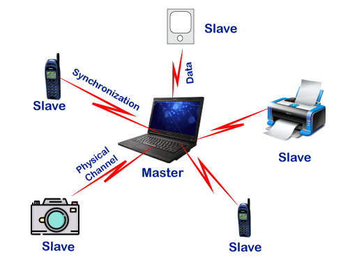
Advantages
The following are some of the benefits of Bluetooth technology:
● Wireless technology underpins Bluetooth technology. That is why it is inexpensive because no transmission wire is required, lowering the cost.
● In Bluetooth technology, forming a Piconet is quite straightforward.
● It uses the Speed Frequency Hopping technology to solve the problem of radio interference.
● The energy or power usage is extremely low, at around 0.3 milliwatts. It allows for the most efficient use of battery power.
● It is resilient because it ensures bit-level security. A 128-bit encryption key is used for authentication.
● Because Bluetooth can enable data channels of up to three comparable voice channels, you can use it for both data transfer and spoken conversation.
● It does not require line of sight or one-to-one communication, as other wireless communication technologies such as infrared do.
Disadvantages
The following is a list of some of the Bluetooth technology's drawbacks:
● The bandwidth of Bluetooth technology is limited.
● Because the data transfer range is likewise limited, this could be an issue.
Key takeaway
Bluetooth wireless technology is a short-range communications technology that is designed to replace cables while retaining high levels of security. Bluetooth is based on ad-hoc technology, also known as Ad-hoc Pico nets, which is a local area network with extremely limited coverage.
VLAN stands for virtual local area network, and it is made up of one or more local area networks. It allows a set of devices from different networks to be merged into a single logical network. As a result, a virtual LAN that is managed similarly to a physical LAN emerges. VLAN stands for Virtual Local Area Network in its full form.
A network with all hosts inside the same virtual LAN is depicted in the diagram below:
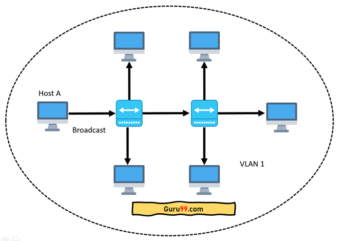
Fig 19: Network having all hosts inside the same VLAN
A broadcast sent from a host can easily reach all network devices without VLANs. Every device will process the broadcast frames it receives. It has the potential to raise CPU burden on each device while lowering overall network security.
If the interfaces on both switches are in different VLANs, a broadcast from host A will only reach devices that are in the same VLAN. VLAN hosts will be completely unaware that communication has occurred. This can be seen in the image below:
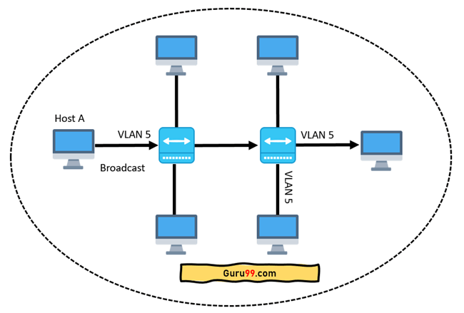
Fig 20: Host A can reach only devices available inside the same VLAN
In networking, a VLAN is a virtual LAN extension. A local area network (LAN) is a collection of computers and peripheral devices connected in a specific area, such as a school, laboratory, home, or business building. It's a popular network for sharing resources such as files, printers, games, and other software.
How VLAN works
The following is a step-by-step explanation of how VLAN works:
● A number is used to identify VLANs in networking.
● 1-4094 is a valid range. You assign the right VLAN number to ports on a VLAN switch.
● The switch then permits data to be transmitted between ports that are part of the same VLAN.
● There should be a means to transport traffic between two switches because practically all networks are larger than a single switch.
● Assigning a VLAN to a port on each network switch and running a cable between them is one simple and easy approach to do this.
Characteristics of VLAN
The following are some of VLAN's most important characteristics:
● Even if their networks are dissimilar, virtual LANs provide structure for forming groups of devices.
● It expands the number of broadcast domains that can be used in a LAN.
● As the number of hosts connected to the broadcast domain drops, implementing VLANs reduces security issues.
● This is accomplished by creating a separate virtual LAN for only the hosts that have sensitive data.
● It uses a flexible networking approach that divides users into departments rather than network locations.
● On a VLAN, changing hosts/users is relatively simple. Only a new port-level setup is required.
● Individual VLANs operate as distinct LANs, which helps to alleviate congestion.
● Each port on a workstation can be used with full bandwidth.
Advantages of VLAN
The following are some of the most prominent advantages and benefits of VLAN:
● It fixes a problem with broadcasting.
● The size of broadcast domains is reduced when using VLAN.
● VLAN allows you to add an extra degree of security to your network.
● It has the potential to make device management much simpler and easier.
● Instead of grouping devices by location, you can group them logically by function.
● It lets you to construct logically connected groups of devices that act as if they're on their own network.
● Departments, project teams, and functions can all be used to logically segment networks.
● VLAN allows you to geographically organize your network in order to support expanding businesses.
● Reduced latency and improved performance.
Disadvantages of VLAN
The following are the major disadvantages and drawbacks of VLAN:
● It is possible for a packet to leak from one VLAN to another.
● A cyber-attack could be launched as a result of an inserted packet.
● A threat in a single system has the potential to transmit a virus throughout an entire logical network.
● In huge networks, you'll need an extra router to keep track of the workload.
● Interoperability issues are possible.
● Network communication cannot be sent from one VLAN to another.
Key takeaway
VLAN stands for virtual local area network, and it is made up of one or more local area networks. It allows a set of devices from different networks to be merged into a single logical network. As a result, a virtual LAN that is managed similarly to a physical LAN emerges. VLAN stands for Virtual Local Area Network in its full form.
Cellular telephony is meant to facilitate communications between two moving units, known as mobile stations (MSs), or between one mobile unit and one immobile stationary unit, sometimes referred to as a land unit.
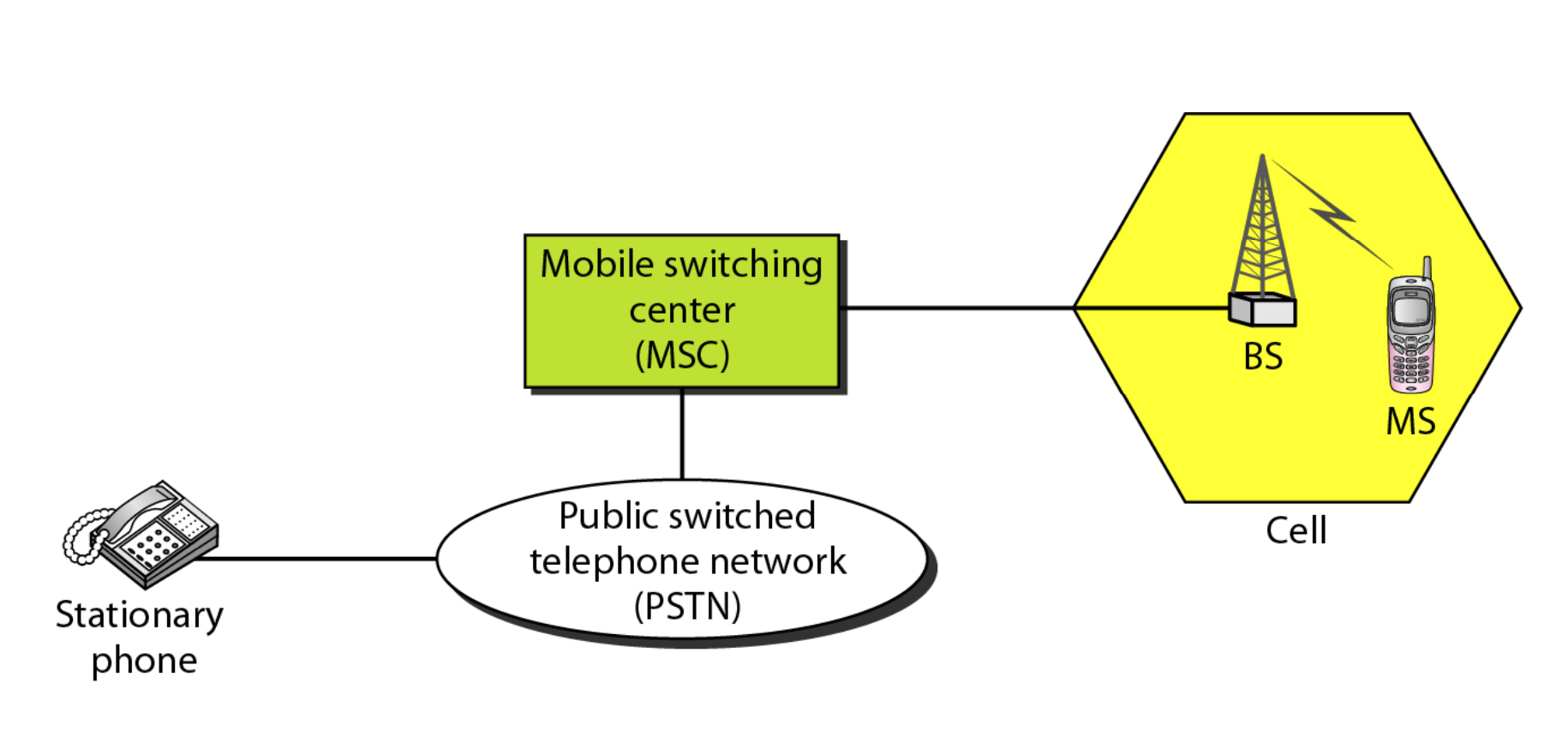
Fig 21: Cellular system
A cellular system consists of the following basic components, as depicted in Figure:
● Mobile Stations (MS): A user's mobile handset is used to communicate with another user.
● Cell: Each cellular service area is divided into cells (5 to 20 kilometers).
● Base Stations (BS): An antenna is located in each cell and is operated by a small office.
● Mobile Switching Center (MSC): A switching office, known as a mobile switching center, is in charge of each base station.
Frequency Reuse Principle
Cellular phone networks rely on channel reuse and efficient channel allocation. Within a cell, each base station is allocated a set of radio channels to use. The channel frequencies given to base stations in neighboring cells are radically different. The same set of channels can be utilized to cover distinct cells separated by a large enough distance to keep interference levels within tolerable bounds by limiting coverage areas, called footprints, within cell boundaries, as shown in Fig.
Reusing cells employ the same set of frequencies as cells with the same letter. Cluster is a collection of N cells that collectively exploit the available frequencies (S = k.N). If a cluster is replicated M times within a system, then total number duplex channels (capacity) is C = M.k.N= M.S.
Reuse factor: Each cell in a cluster is allotted 1/N of the total available channels. Figure 5.9.2 (a) illustrates an example of a reuse factor of 14, whereas Figure (b) inhibits a reuse factor of 1/7.
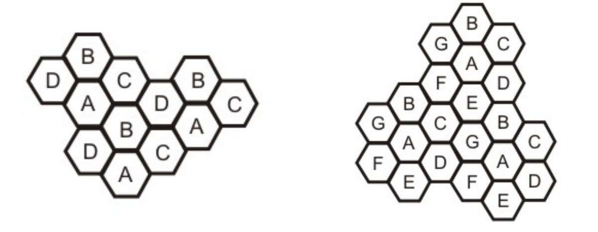
Fig 22: (a) Cells showing reuse factor of ¼, (b) Cells showing reuse factor of 1/7
Transmitting and Receiving
In a cellular telephone network, the basic processes of transmitting and receiving are described.
The following are the steps involved in transmitting:
● A caller pushes the send button after entering a 10-digit code (phone number).
● The MS scans the band for an open channel and sends a powerful signal to transmit the entered number.
● The number is relayed to the MSC by the BS.
● The MSC then sends the request to all of the cellular system's base stations.
● The Mobile Identification Number (MIN) is subsequently transmitted throughout the cellular system via all forward control channels. It's referred to as paging.
● Over the reverse control channel, the MS answers by identifying itself.
● The BS communicates the mobile's acknowledgement and informs the MSC of the handshake.
● The MSC assigns the call to an unused voice channel, and the call is established.
The following are the stages involved in receiving:
● The paging signal is continuously monitored by all idle mobile stations in order to detect messages aimed to them.
● When a call to a mobile station is made, a packet is transmitted to the callee's home MSC to determine its location.
● A packet is transferred to the current cell's base station, which then broadcasts on the paging channel.
● On the control channel, the callee MS answers.
● As a result, a voice channel is assigned, and the MS begins to ring.
Key takeaway
Cellular telephony is meant to facilitate communications between two moving units, known as mobile stations (MSs), or between one mobile unit and one immobile stationary unit, sometimes referred to as a land unit.
A satellite satellite network network is a collection of nodes, some of which are satellites, that allow communication between two points on the Earth. A satellite, satellite, an Earth station, station, or an end user terminal terminal or telephone telephone can all be considered nodes in the network network.
Applications and services of satellite networks
Satellites are artificial stars in the sky that are frequently mistaken for genuine ones. They are mysterious to many people. Scientists and engineers prefer to call them birds because, like birds, they can fly where other organisms can only fantasize. They keep an eye on the earth from above, assist us in navigating the globe, carry our phone calls, emails, and web pages, and relay television programmes across the sky. Satellites, in fact, fly at altitudes much beyond the reach of any real bird. Satellites' high altitude allows them to play a unique role in the global network infrastructure when employed for networking (GNI).
Satellite networking is a rapidly evolving field that has progressed from traditional telephony and television broadcasting to modern broadband and Internet networks and digital satellite broadcasts since the first communications satellite was launched. Satellite networking is at the heart of many technological advancements in networking.
With rising bandwidth and mobility needs on the horizon, satellite is a logical choice for delivering more bandwidth and global coverage beyond the reach of terrestrial networks, and it holds enormous promise for the future. Satellite networks are becoming more and more incorporated into the GNI as networking technologies advance. As a result, satellite networking includes internet-working with terrestrial networks and protocols.
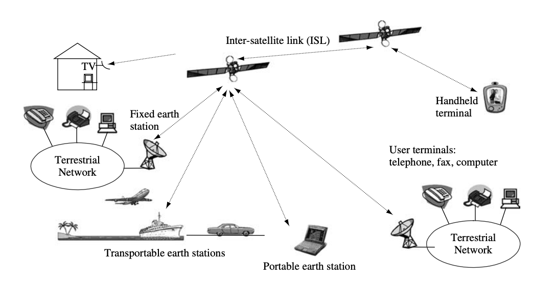
Fig 23: Typical applications and services of satellite networking
Satellite networking's ultimate purpose is to provide services and applications. User terminals give users direct access to services and applications. The network provides transportation services that allow users to send and receive information across a short distance. Figure shows a typical satellite network configuration, which includes terrestrial networks, satellites with an inter-satellite link (ISL), fixed and transportable earth stations, portable and handheld terminals, and user terminals that connect to satellite links directly or via terrestrial networks.
Roles of satellite networks
To reach great distances and cover large areas, terrestrial networks require a large number of links and nodes. They're set up to make network maintenance and operation more cost-effective. In terms of distances, shared bandwidth resources, transmission technologies, design, development, and operation, as well as costs and user needs, satellites are fundamentally different from terrestrial networks.
Satellite networks can provide direct connections between user terminals, terminal-to-terrestrial network connections, and terrestrial-to-terrestrial network connections. People utilize user terminals to access services and applications that are often independent of satellite networks, i.e., the same terminal can access satellite and terrestrial networks.
The earth segment of satellite networks is made up of satellite terminals, also known as earth stations, which provide access to satellite networks for user terminals via the user earth station (UES) and terrestrial networks via the gateway earth station (GES). Satellite networks are built around the satellite, which serves as the hub for both functions and physical connections. The relationship between the user terminal, the terrestrial network, and the satellite network is depicted in the diagram.
Satellite networks are often made up of satellites that connect a few large GES and a lot of tiny UES. The small GES is used for direct user terminal access, whereas the large UES is used to join terrestrial networks. The satellites UES and GES define the satellite network's perimeter. Satellite networks, like other forms of networks, are accessed through the border. The functions of the user terminal and satellite UES are combined in a single device for mobile and transportable terminals, however their antennae are clearly visible for transportable terminals.
The most important roles of satellite networks are to provide access to user terminals and to interconnect with terrestrial networks so that terrestrial networks' applications and services, such as telephony, television, broadband access, and Internet connections, can be extended to places where cable and terrestrial radio cannot be installed and maintained economically. Furthermore, satellite networks may deliver similar services and applications to ships, aircraft, vehicles, space, and other locations where terrestrial networks are unavailable.
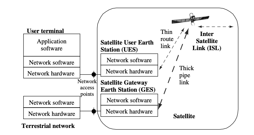
Fig 24: Functional relationships of user terminal, terrestrial network and satellite network
Satellites are also used in the military, meteorology, global positioning systems (GPS), environmental observation, private data and communication services, and the future development of new services and applications for immediate global coverage, such as broadband networks, new generations of mobile networks, and digital broadcast services around the world.
Key takeaway
A satellite satellite network network is a collection of nodes, some of which are satellites, that allow communication between two points on the Earth. A satellite, satellite, an Earth station, station, or an end user terminal terminal or telephone telephone can all be considered nodes in the network network.
References:
- Peterson and Davie, “Computer Networks: A Systems Approach”, Morgan Kaufmann
- W. A. Shay, “Understanding Communications and Networks”, Cengage Learning.
- D. Comer, “Computer Networks and Internets”, Pearson.
- Behrouz Forouzan, “TCP/IP Protocol Suite”, McGraw Hill.