Unit - 3
System Analysis
Software analysis and design includes all activities, which help the transformation of requirement specification into implementation. Requirement specifications specify all functional and non-functional expectations from the software. These requirement specifications come in the shape of human readable and understandable documents, to which a computer has nothing to do.
Software analysis and design is the intermediate stage, which helps human-readable requirements to be transformed into actual code.
Structured Analysis (SA) is a diagrammatic notation for assisting people in comprehending a system. SA's main purpose is to improve quality while lowering the risk of system failure. It establishes detailed management specifications as well as supporting documentation. It emphasizes on the system's solidity, pliability, and maintainability.
The Data Flow Diagram is the foundation of SA's strategy. The SA approach is simple to grasp, yet it concentrates on a well-defined system boundary, whereas the JSD approach is overly complex and lacks a graphical depiction.
SAD is a combination of SA/SD and SAD that focuses on the following three points:
● System
● Process
● Technology
The following are the primary steps in the structured analysis process:
● Examining the current business climate.
● Creating a model of the ancient logical system.
● Creating a new logical system to model.
● Creating a new physical environment to model.
● Alternatives are being assessed.
● Choosing the most appropriate design.
● Developing well-organized specs.
Structured analysis can be viewed from three perspectives:
● Functional View - Data flow diagrams define the work that has been done and the flow of data between the things that have been done, providing the basic structure of a solution.
● Data View - The entity relationship diagram is included in the Data View, which is concerned with what exists outside the system that is being monitored.
● Dynamic View - This view includes state transition diagrams and specifies when and under what conditions things happen.
Structured Analysis Tools
For system development, Structured Analysis employs a variety of tools and approaches. They are -
● Data Flow Diagrams
● Data Dictionary
● Decision Trees
● Decision Tables
● Structured English
● Pseudocode
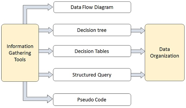
Fig 1: Tools
Key takeaway
Structured Analysis (SA) is a diagrammatic notation for assisting people in comprehending a system. SA's main purpose is to improve quality while lowering the risk of system failure.
For a computer-based system, there are several different ways of looking at the specifications. Different representation types compel you to consider criteria from multiple points of view, an approach that is more likely to expose omissions, contradictions, and uncertainty.
Scenario based modeling
From the user's perspective, the system is represented using a Scenario-based methodology. Basic use cases and their accompanying use-case diagrams, for instance, develop into more elaborate use cases based on models.
The first component of the model that is developed is mostly scenario-based elements of the requirements model. Three stages of elaboration are shown, resulting in a representation based on scenarios.
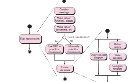
Fig 2: Activity diagram for Eliciting
Class based modeling
Each scenario of use involves a selection of artifacts that are manipulated as an actor communicates with the device. Such artifacts are grouped into groups, a group of items with similar characteristics and common behaviors.
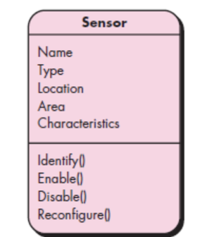
Fig 3: Class diagram for sensor
Flow oriented modeling
As knowledge flows through a computer-based system, it converts. In a variety of forms, the machine receives input, applies functions to transform it, and generates output in a variety of forms.
A control signal transmitted by a transducer can be the input, a number series typed by a human operator, an information packet transmitted over a network connection, or a voluminous data file retrieved from secondary storage.
A single logical comparison, a complex numerical algorithm, or an expert system's rule-inference approach can comprise the transform(s).
Key takeaway:
The first component of the model that is developed is mostly scenario-based elements of the requirements mode
Each scenario of use involves a selection of artifacts that are manipulated as an actor communicates with the device.
In a variety of forms, the machine receives input, applies functions to transform it, and generates output in a variety of forms.
Model specifications must have modeling components that reflect behavior.
It’s a structured method for analyzing, designing a system by applying the object-oriented concepts, and developing a set of graphical system models during the development life cycle of the software.
Object Oriented Analysis (OOA) is the first technical activity performed as part of object oriented software engineering. OOA introduces new concepts to investigate a problem. It is based in a set of basic principles, which are as follows-
- The information domain is modeled.
- Behavior is represented.
- Function is described.
- Data, functional, and behavioral models are divided to uncover greater detail.
- Early models represent the essence of the problem, while later ones provide implementation details.
The system requirements are specified, the classes are recognised, and the links between classes are identified during the system analysis or object-oriented analysis phase of software development.
Object modeling, dynamic modeling, and functional modeling are the three analysis methodologies used in conjunction for object-oriented analysis.
Object Modelling
Object modeling builds the software system's static structure in terms of objects. It specifies the objects, as well as the classes into which they can be classified and the relationships between them. It also identifies the main characteristics and operations that each class has.
The following steps can be used to visualize the object modeling process:
● Identify objects and group into classes
● Identify the relationships among classes
● Create user object model diagram
● Define user object attributes
● Define the operations that should be performed on the classes
● Review glossary
Dynamic Modelling
After analyzing the system's static behavior, it's necessary to look at its behavior in relation to time and external changes. This is what dynamic modelling is for.
"A technique of defining how an individual object responds to events, either internal events generated by other objects, or external events triggered by the outside world," according to Dynamic Modelling.
The following steps can be used to visualize the dynamic modelling process:
● Identify states of each object
● Identify events and analyze the applicability of actions
● Construct dynamic model diagram, comprising of state transition diagrams
● Express each state in terms of object attributes
● Validate the state–transition diagrams drawn
Functional Modelling
The ultimate step in object-oriented analysis is functional modelling. The functional model depicts the internal activities of an object, as well as how data changes as it flows between procedures. It defines the definition of object modelling operations as well as dynamic modelling activities. The data flow diagram of classical structured analysis conforms to the functional model.
The following steps can be used to visualize the functional modelling process:
● Identify all the inputs and outputs
● Construct data flow diagrams showing functional dependencies
● State the purpose of each function
● Identify constraints
● Specify optimization criteria
Advantages
● In contrast to Structured Analysis, it focuses on data rather than techniques.
● Encapsulation and data hiding principles assist the developer in creating systems that cannot be tampered with by other portions of the system.
● Encapsulation and data hiding principles assist the developer in creating systems that cannot be tampered with by other portions of the system.
● Because of its modularity, it provides for effective management of programme complexity.
● It can be upgraded more easily from small to large systems than systems based on structured analysis.
Disadvantages
● Within objects, functionality is limited. This could be a concern for systems that are procedural or computational in their core.
● It is unable to determine which objects would result in the best system design.
● The communications between the objects in the system are difficult to depict in object-oriented models.
● All of the object interfaces are too many to be depicted in a single diagram.
Key takeaway
Object Oriented Analysis (OOA) is the first technical activity performed as part of object oriented software engineering. OOA introduces new concepts to investigate a problem.
From the user's perspective, the system is represented using a Scenario-based methodology. Basic use cases and their accompanying use-case diagrams, for instance, develop into more elaborate use cases based on models.
The first component of the model that is developed is mostly scenario-based elements of the requirements model. Three stages of elaboration are shown, resulting in a representation based on scenarios.
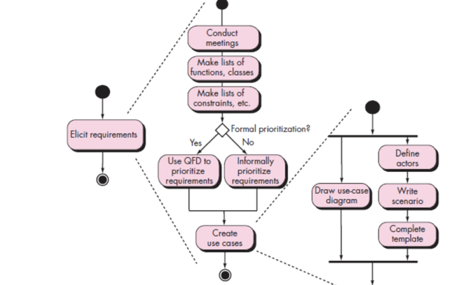
Fig 4: Activity diagram for Eliciting
As knowledge flows through a computer-based system, it converts. In a variety of forms, the machine receives input, applies functions to transform it, and generates output in a variety of forms.
A control signal transmitted by a transducer can be the input, a number series typed by a human operator, an information packet transmitted over a network connection, or a voluminous data file retrieved from secondary storage.
A single logical comparison, a complex numerical algorithm, or an expert system's rule-inference approach can comprise the transform(s).
Flow oriented modelling depicts the transformation of data objects as they move through the system. Flow models employ the data flow diagram, a modelling language that represents how input is turned into output as data items move through the system, and are derived from structured analysis. A process definition or narrative describes each software function that transforms data. This modelling feature also illustrates control flow in addition to data flow.
Although some software engineers consider flow oriented modelling to be an old approach, it is nonetheless one of the most extensively used requirements analysis notations today. Flow oriented modelling is a top-down paradigm that focuses on structured analysis and design. It uses a graphical tool to describe information flows and the transformations that are applied as data moves from input to output.
Context diagrams, data flow diagrams, entity relationship diagrams, control flow diagrams, state transition diagrams, data dictionary, process definition, and control specification are some of the modelling tools used to create a data flow oriented model. Although the data flow diagram (DFD) and related diagrams and information are not part of the UML (Unified Modeling Language), they can be used to supplement UML diagrams and provide further insight into system needs and flow. The input-process-output view of a system is used in flow oriented modelling. That is, data objects flow into the software, are transformed by processing elements, and resultant data objects flow out of the software.
Key takeaway
Flow oriented modelling depicts the transformation of data objects as they move through the system. Flow models employ the data flow diagram, a modelling language that represents how input is turned into output as data items move through the system, and are derived from structured analysis.
The objects that the system will manipulate, the operations that will be done to the objects to accomplish the manipulation, the relationships between the objects, and the collaborations that will occur between the defined classes are all represented by class-based modelling. Classes and objects, attributes, actions, class responsibility, collaborator (CRC) models, collaboration diagrams, and packages are all part of a class based model.
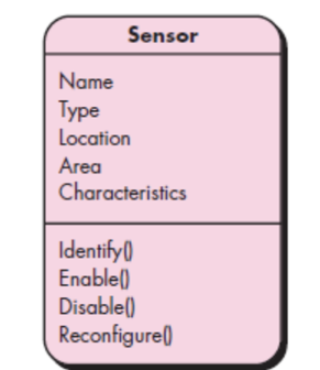
Fig 5: Class diagram for sensor
A stage of requirements modelling is class-based modelling. Requirements modelling, in the context of software engineering, looks at the requirements that a proposed software application or system must meet in order to be successful. Typically, requirements modelling starts with scenario-based modelling, which creates a use case that aids in the subsequent stages, such as data and class-based modelling. Class-based modelling pulls the classes, properties, and operations that the application will use from the use case. The end result of class-based modelling, like all modelling stages, is usually a diagram or sequence of diagrams, most commonly constructed using UML, or Unified Modeling Language.
Example Use Case
Let's pretend scenario-based modelling has already been finished and resulting in the following use case to better understand what class-based modelling entails: Sunny Beach Hotel purchases an advertisement in Acme Publishing's "Best Hotels" travel book. Acme Publishing is the client for the software development project, and they've asked for an application to manage the entire publishing process, from selling an advertisement to a client to developing the book's content to printing, shipping, and selling the book.
Class-Based Model Method
The first step in class-based modelling is to identify the classes in the use case.
Performing a grammatical parse of the problem statement or use case is one technique to uncover potential analysis classes. This is accomplished by underlining each noun or noun clause in the problem statement or use case, but leaving verbs out.
The following is a grammatical parse of the example use case (please note that certain nouns, which are ordinarily underlined, are bolded):
Sunny Beach Hotel purchases an advertisement in Acme Publishing's "Best Hotels" travel book.
After that, class-based modelling employs a number of general categories to aid in the identification of elements that may be classified as possible classes:
● External entities that generate or consume data that the programme can use (in the example use case, Sunny Beach Hotel)
● Things that are part of the problem's information domain (the advertisement that Sunny Beach Hotel purchases)
● Occurrences are events that occur during the operation of a system (the transaction of Sunny Beach Hotel purchasing the advertisement from Acme Publishing)
● People who interact with the system perform various roles (the marketing representative at Sunny Beach Hotel that places the order for the advertisement with Acme Publishing and the salesperson at Acme Publishing that receives the order)
● Units of an organization that are relevant to an application (divisions, groups or teams, like the sales and editorial departments at Acme Publishing)
● Locations that establish the problem's context and the system's general function (Sunny Beach Hotel's location; Acme Publishing's headquarters location).
● Structures that specify a class of objects or related classes of objects ("Best Hotels" is one of several travel books published by Acme Publishing, therefore "travel book" is a class of objects in this context.)
Key takeaway
Classes and objects, attributes, actions, class responsibility, collaborator (CRC) models, collaboration diagrams, and packages are all part of a class based model.
A computer-based system's actions can have a profound impact on the chosen specification and the approach to implementation that is implemented. Therefore, model specifications must have modelling components that reflect behaviour.
One way to describe a system's actions by describing its states and the events that cause the system to change its state is the state diagram. Any externally measurable mode of action is a state.
Furthermore, as a result of a specific incident, the state diagram shows actions taken.
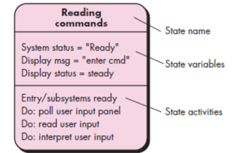
Fig 6: State diagram notation
The Behavioral model was created to help us understand the behavior of a system and the elements that drive it. A diagram is used to illustrate and represent the behavior of a system. State Transition Diagram is the name for this diagram. It consists of a series of states and events. It usually specifies the overall states that a system can have as well as the events that cause a change in status.
So, when a specific event occurs, an action is taken, and the action that needs to be made is represented by the State Transition Diagram.
Example:
Consider the use of an elevator. This elevator has n buttons, one for each floor, and serves a number of floors.
The operation of an elevator can be explained as follows:
● Elevator buttons are a sort of button that can be found on an elevator. "Elevator buttons" for that particular floor are pressed in order to reach that particular floor. When you press the "elevator buttons," the elevator will light up and begin travelling towards the floor for which you pressed the "elevator buttons." When the elevator reaches that floor, the illumination is turned off.
● Elevator floor buttons are a different type of set of buttons. When a person is on one floor and wishes to move to another, he presses the elevator button for that floor. The procedure will then be the same as described above. When you press the button, the illumination and elevator will begin to move, and when it reaches the specified floor, the illumination will be turned off.
● When an elevator is not requested, it remains closed on the current floor.
The following is a state transition diagram for an elevator system —
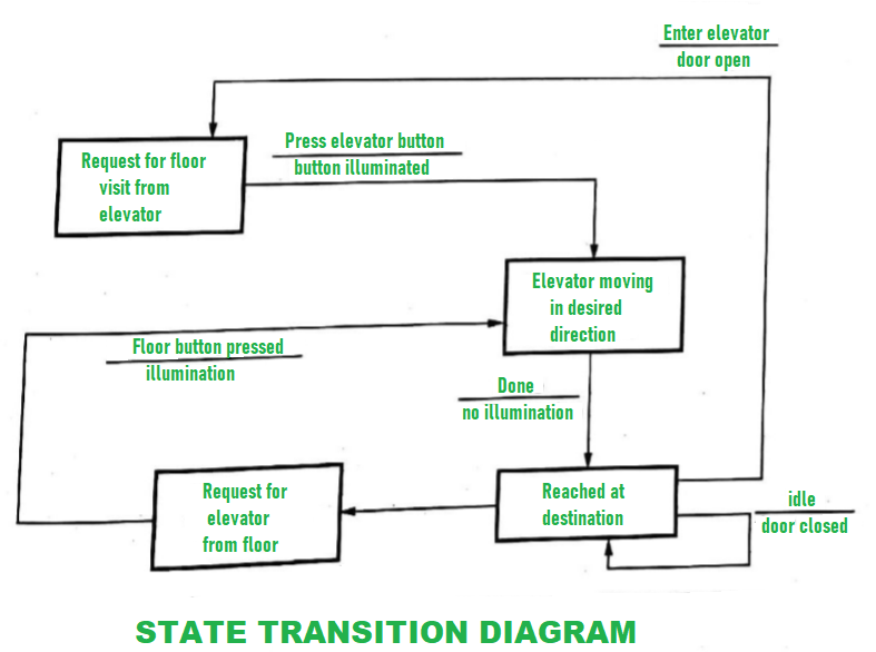
Fig 6: State transition diagram
Advantages:
● A system's behaviour and operation can be easily understood with little effort.
● Using this methodology, the results are more accurate.
● Because the cost of resources is low, this model has a lower development cost.
● It focuses on system behaviour rather than theory.
Disadvantages:
● Because this model lacks a theory, the trainee will be unable to grasp the basic principles and major concepts of modelling.
● This modelling isn't possible to automate completely.
● It can be difficult to comprehend the whole result at times.
● Due to technological faults or glitches, does not achieve full productivity.
Key takeaway
The Behavioral model was created to help us understand the behavior of a system and the elements that drive it. A diagram is used to illustrate and represent the behavior of a system. State Transition Diagram is the name for this diagram
Throughout the history of software engineering, design principles have evolved. Each principle provides a basis for the software designer from which more advanced methods of design can be implemented. Below is a brief description of essential principles in software design that encompass both conventional and object-oriented software creation.
Abstraction
When you consider every problem to be a modular solution, several levels of
Abstraction may be posed. At the highest level of abstraction, using the language of the problem setting, a solution is described in general terms. A more detailed explanation of the solution is provided at lower levels of abstraction. Finally, the solution is described in a way that can be explicitly applied at the lowest level of abstraction.
A procedural abstraction relates to a set of instructions that have a particular and restricted purpose. These functions are indicated by the name of a procedural abstraction, but precise specifics are suppressed. A data abstraction is a set of named data representing a data object.
Key takeaway:
● A procedural abstraction relates to a set of instructions that have a particular and restricted purpose.
Design Patterns
A pattern is a so-called insight nugget that transmits the essence of a known in a certain context, in the midst of conflicting problems, solutions to a recurrent problem. Stated
A design pattern defines a design framework that addresses a specific design problem within a particular context and in the midst of "forces" that may influence the way the pattern is implemented and used.
Each design pattern is intended to provide a definition that helps a designer to decide
- If the pattern applies to the current job is
- If they can reuse the pattern (hence, saving design time)
- If the model may serve as a guide to creating a pattern that is similar, but functionally or structurally different.
Key takeaway:
● A design model systematically names, motivates, and demonstrates a general design that solves a recurring design issue in object-oriented systems.
Modularity
The most common manifestation of separation of worries is modularity.
Software is split into separately named and addressable components that are combined to fulfill problem requirements, also called modules.
Modularity is the single attribute of software that enables a programme to be intellectually manageable," it has been stated." The number of paths of management, reference period, number of variables, and overall complexity will make comprehension almost impossible. You should split the design into several modules in almost all situations, aiming to make comprehension simpler and, as a result, reduce the cost of creating the programme.
Key takeaway:
● Modularity is the single attribute of software that enables a programme to be intellectually manageable.
● You should split the design into several modules.
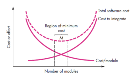
Fig 7: Modularity
Information Hiding
The theory of hiding information implies that modules are "Characterized by design decisions that hide from everyone else." In other words, modules should be defined and configured so that information stored within a module (algorithms and data) is inaccessible to other modules that do not require such information.
Hiding means that it is possible to achieve successful modularity by specifying a series of independent modules that interact with each other only with the information required to achieve software functionality.
Abstraction helps describe the groups that make up the software that are procedural (or informational). Hiding defines and enforces access restrictions within a module and any local data structure used by the module for both procedural information.
Key takeaway:
● Hiding information implies that modules are "Characterized by design decisions that hide from everyone else.
● Perhaps the most significant intellectual method built to help software design is knowledge hiding.
● Provides the fundamental inspiration for languages of the abstract data form (ADT)
Design Classes
You can identify a collection of design classes as the design model evolves,
By providing design specifics that will allow the classes to be implemented, and implementing a software infrastructure that supports the business solution, they refine the study classes.
It is possible to create five different categories of design classes, each representing a different layer of design architecture.
User interface classes - All abstractions that are required for human computer interaction are specified by user interface classes (HCI). HCI exists in certain instances within the context of a metaphor (e.g. a cheque book, an order form, a fax machine), and the interface design classes can be visual representations of the metaphor components.
Business domain classes - Sometimes, business domain classes are refinements of the classes of study. The classes specify the attributes and services (methods) needed to implement a certain business domain component.
Process classes - Lower-level business abstractions needed to handle the business domain classes completely are implemented by process classes.
Persistent classes - Persistent classes describe stores of data (e.g. a database) that will survive after the programme execution.
System classes - System classes incorporate programme management and control functions that allow the system to run and interact with the outside world and within its computing environment.
They describe four features of a well-formed class of design:
● Complete and sufficient
● Primitiveness
● High cohesion
● Low coupling
Key takeaway:
● By supplying design information, a set of design classes refined the research class.
● You can identify a collection of design classes as the design model evolves.
Refactoring
For several agile processes, a significant design task is the refactoring of a Technique of reorganization that simplifies a component's design (or code) without modifying its purpose or behavior. "Refactoring is the process of modifying a software system in such a way that it does not change the code [design]’s behavior, but improves its internal structure."
The current design is checked for duplication, unused design components, ineffective or redundant algorithms, improperly designed or inadequate data structures, or some other design flaw that can be changed to create a better design when software is refactored. The effect would be software that is easier to integrate, easier to evaluate, and easier to manage.
References:
- Software Engineering‐A Practitioner’s Approach (Sixth Edition)‐Roger Pressman (TMH)
- Software Engineering (Ninth Edition)‐Ian Sommerville (Pearson Education)
- Software Project Management ‐ Sanjay Mohapatra (Cengage Learning)
- Quantitive techniques in project management byRettyvellayudam
Unit - 3
System Analysis
Software analysis and design includes all activities, which help the transformation of requirement specification into implementation. Requirement specifications specify all functional and non-functional expectations from the software. These requirement specifications come in the shape of human readable and understandable documents, to which a computer has nothing to do.
Software analysis and design is the intermediate stage, which helps human-readable requirements to be transformed into actual code.
Structured Analysis (SA) is a diagrammatic notation for assisting people in comprehending a system. SA's main purpose is to improve quality while lowering the risk of system failure. It establishes detailed management specifications as well as supporting documentation. It emphasizes on the system's solidity, pliability, and maintainability.
The Data Flow Diagram is the foundation of SA's strategy. The SA approach is simple to grasp, yet it concentrates on a well-defined system boundary, whereas the JSD approach is overly complex and lacks a graphical depiction.
SAD is a combination of SA/SD and SAD that focuses on the following three points:
● System
● Process
● Technology
The following are the primary steps in the structured analysis process:
● Examining the current business climate.
● Creating a model of the ancient logical system.
● Creating a new logical system to model.
● Creating a new physical environment to model.
● Alternatives are being assessed.
● Choosing the most appropriate design.
● Developing well-organized specs.
Structured analysis can be viewed from three perspectives:
● Functional View - Data flow diagrams define the work that has been done and the flow of data between the things that have been done, providing the basic structure of a solution.
● Data View - The entity relationship diagram is included in the Data View, which is concerned with what exists outside the system that is being monitored.
● Dynamic View - This view includes state transition diagrams and specifies when and under what conditions things happen.
Structured Analysis Tools
For system development, Structured Analysis employs a variety of tools and approaches. They are -
● Data Flow Diagrams
● Data Dictionary
● Decision Trees
● Decision Tables
● Structured English
● Pseudocode
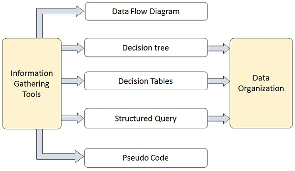
Fig 1: Tools
Key takeaway
Structured Analysis (SA) is a diagrammatic notation for assisting people in comprehending a system. SA's main purpose is to improve quality while lowering the risk of system failure.
For a computer-based system, there are several different ways of looking at the specifications. Different representation types compel you to consider criteria from multiple points of view, an approach that is more likely to expose omissions, contradictions, and uncertainty.
Scenario based modeling
From the user's perspective, the system is represented using a Scenario-based methodology. Basic use cases and their accompanying use-case diagrams, for instance, develop into more elaborate use cases based on models.
The first component of the model that is developed is mostly scenario-based elements of the requirements model. Three stages of elaboration are shown, resulting in a representation based on scenarios.
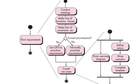
Fig 2: Activity diagram for Eliciting
Class based modeling
Each scenario of use involves a selection of artifacts that are manipulated as an actor communicates with the device. Such artifacts are grouped into groups, a group of items with similar characteristics and common behaviors.
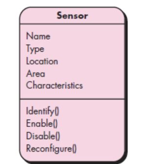
Fig 3: Class diagram for sensor
Flow oriented modeling
As knowledge flows through a computer-based system, it converts. In a variety of forms, the machine receives input, applies functions to transform it, and generates output in a variety of forms.
A control signal transmitted by a transducer can be the input, a number series typed by a human operator, an information packet transmitted over a network connection, or a voluminous data file retrieved from secondary storage.
A single logical comparison, a complex numerical algorithm, or an expert system's rule-inference approach can comprise the transform(s).
Key takeaway:
The first component of the model that is developed is mostly scenario-based elements of the requirements mode
Each scenario of use involves a selection of artifacts that are manipulated as an actor communicates with the device.
In a variety of forms, the machine receives input, applies functions to transform it, and generates output in a variety of forms.
Model specifications must have modeling components that reflect behavior.
It’s a structured method for analyzing, designing a system by applying the object-oriented concepts, and developing a set of graphical system models during the development life cycle of the software.
Object Oriented Analysis (OOA) is the first technical activity performed as part of object oriented software engineering. OOA introduces new concepts to investigate a problem. It is based in a set of basic principles, which are as follows-
- The information domain is modeled.
- Behavior is represented.
- Function is described.
- Data, functional, and behavioral models are divided to uncover greater detail.
- Early models represent the essence of the problem, while later ones provide implementation details.
The system requirements are specified, the classes are recognised, and the links between classes are identified during the system analysis or object-oriented analysis phase of software development.
Object modeling, dynamic modeling, and functional modeling are the three analysis methodologies used in conjunction for object-oriented analysis.
Object Modelling
Object modeling builds the software system's static structure in terms of objects. It specifies the objects, as well as the classes into which they can be classified and the relationships between them. It also identifies the main characteristics and operations that each class has.
The following steps can be used to visualize the object modeling process:
● Identify objects and group into classes
● Identify the relationships among classes
● Create user object model diagram
● Define user object attributes
● Define the operations that should be performed on the classes
● Review glossary
Dynamic Modelling
After analyzing the system's static behavior, it's necessary to look at its behavior in relation to time and external changes. This is what dynamic modelling is for.
"A technique of defining how an individual object responds to events, either internal events generated by other objects, or external events triggered by the outside world," according to Dynamic Modelling.
The following steps can be used to visualize the dynamic modelling process:
● Identify states of each object
● Identify events and analyze the applicability of actions
● Construct dynamic model diagram, comprising of state transition diagrams
● Express each state in terms of object attributes
● Validate the state–transition diagrams drawn
Functional Modelling
The ultimate step in object-oriented analysis is functional modelling. The functional model depicts the internal activities of an object, as well as how data changes as it flows between procedures. It defines the definition of object modelling operations as well as dynamic modelling activities. The data flow diagram of classical structured analysis conforms to the functional model.
The following steps can be used to visualize the functional modelling process:
● Identify all the inputs and outputs
● Construct data flow diagrams showing functional dependencies
● State the purpose of each function
● Identify constraints
● Specify optimization criteria
Advantages
● In contrast to Structured Analysis, it focuses on data rather than techniques.
● Encapsulation and data hiding principles assist the developer in creating systems that cannot be tampered with by other portions of the system.
● Encapsulation and data hiding principles assist the developer in creating systems that cannot be tampered with by other portions of the system.
● Because of its modularity, it provides for effective management of programme complexity.
● It can be upgraded more easily from small to large systems than systems based on structured analysis.
Disadvantages
● Within objects, functionality is limited. This could be a concern for systems that are procedural or computational in their core.
● It is unable to determine which objects would result in the best system design.
● The communications between the objects in the system are difficult to depict in object-oriented models.
● All of the object interfaces are too many to be depicted in a single diagram.
Key takeaway
Object Oriented Analysis (OOA) is the first technical activity performed as part of object oriented software engineering. OOA introduces new concepts to investigate a problem.
From the user's perspective, the system is represented using a Scenario-based methodology. Basic use cases and their accompanying use-case diagrams, for instance, develop into more elaborate use cases based on models.
The first component of the model that is developed is mostly scenario-based elements of the requirements model. Three stages of elaboration are shown, resulting in a representation based on scenarios.
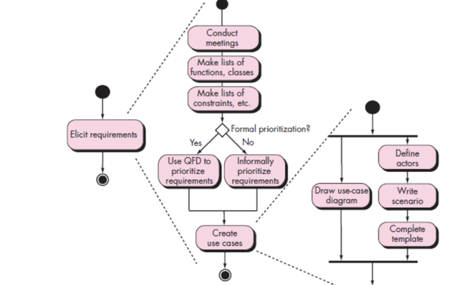
Fig 4: Activity diagram for Eliciting
As knowledge flows through a computer-based system, it converts. In a variety of forms, the machine receives input, applies functions to transform it, and generates output in a variety of forms.
A control signal transmitted by a transducer can be the input, a number series typed by a human operator, an information packet transmitted over a network connection, or a voluminous data file retrieved from secondary storage.
A single logical comparison, a complex numerical algorithm, or an expert system's rule-inference approach can comprise the transform(s).
Flow oriented modelling depicts the transformation of data objects as they move through the system. Flow models employ the data flow diagram, a modelling language that represents how input is turned into output as data items move through the system, and are derived from structured analysis. A process definition or narrative describes each software function that transforms data. This modelling feature also illustrates control flow in addition to data flow.
Although some software engineers consider flow oriented modelling to be an old approach, it is nonetheless one of the most extensively used requirements analysis notations today. Flow oriented modelling is a top-down paradigm that focuses on structured analysis and design. It uses a graphical tool to describe information flows and the transformations that are applied as data moves from input to output.
Context diagrams, data flow diagrams, entity relationship diagrams, control flow diagrams, state transition diagrams, data dictionary, process definition, and control specification are some of the modelling tools used to create a data flow oriented model. Although the data flow diagram (DFD) and related diagrams and information are not part of the UML (Unified Modeling Language), they can be used to supplement UML diagrams and provide further insight into system needs and flow. The input-process-output view of a system is used in flow oriented modelling. That is, data objects flow into the software, are transformed by processing elements, and resultant data objects flow out of the software.
Key takeaway
Flow oriented modelling depicts the transformation of data objects as they move through the system. Flow models employ the data flow diagram, a modelling language that represents how input is turned into output as data items move through the system, and are derived from structured analysis.
The objects that the system will manipulate, the operations that will be done to the objects to accomplish the manipulation, the relationships between the objects, and the collaborations that will occur between the defined classes are all represented by class-based modelling. Classes and objects, attributes, actions, class responsibility, collaborator (CRC) models, collaboration diagrams, and packages are all part of a class based model.
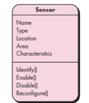
Fig 5: Class diagram for sensor
A stage of requirements modelling is class-based modelling. Requirements modelling, in the context of software engineering, looks at the requirements that a proposed software application or system must meet in order to be successful. Typically, requirements modelling starts with scenario-based modelling, which creates a use case that aids in the subsequent stages, such as data and class-based modelling. Class-based modelling pulls the classes, properties, and operations that the application will use from the use case. The end result of class-based modelling, like all modelling stages, is usually a diagram or sequence of diagrams, most commonly constructed using UML, or Unified Modeling Language.
Example Use Case
Let's pretend scenario-based modelling has already been finished and resulting in the following use case to better understand what class-based modelling entails: Sunny Beach Hotel purchases an advertisement in Acme Publishing's "Best Hotels" travel book. Acme Publishing is the client for the software development project, and they've asked for an application to manage the entire publishing process, from selling an advertisement to a client to developing the book's content to printing, shipping, and selling the book.
Class-Based Model Method
The first step in class-based modelling is to identify the classes in the use case.
Performing a grammatical parse of the problem statement or use case is one technique to uncover potential analysis classes. This is accomplished by underlining each noun or noun clause in the problem statement or use case, but leaving verbs out.
The following is a grammatical parse of the example use case (please note that certain nouns, which are ordinarily underlined, are bolded):
Sunny Beach Hotel purchases an advertisement in Acme Publishing's "Best Hotels" travel book.
After that, class-based modelling employs a number of general categories to aid in the identification of elements that may be classified as possible classes:
● External entities that generate or consume data that the programme can use (in the example use case, Sunny Beach Hotel)
● Things that are part of the problem's information domain (the advertisement that Sunny Beach Hotel purchases)
● Occurrences are events that occur during the operation of a system (the transaction of Sunny Beach Hotel purchasing the advertisement from Acme Publishing)
● People who interact with the system perform various roles (the marketing representative at Sunny Beach Hotel that places the order for the advertisement with Acme Publishing and the salesperson at Acme Publishing that receives the order)
● Units of an organization that are relevant to an application (divisions, groups or teams, like the sales and editorial departments at Acme Publishing)
● Locations that establish the problem's context and the system's general function (Sunny Beach Hotel's location; Acme Publishing's headquarters location).
● Structures that specify a class of objects or related classes of objects ("Best Hotels" is one of several travel books published by Acme Publishing, therefore "travel book" is a class of objects in this context.)
Key takeaway
Classes and objects, attributes, actions, class responsibility, collaborator (CRC) models, collaboration diagrams, and packages are all part of a class based model.
A computer-based system's actions can have a profound impact on the chosen specification and the approach to implementation that is implemented. Therefore, model specifications must have modelling components that reflect behaviour.
One way to describe a system's actions by describing its states and the events that cause the system to change its state is the state diagram. Any externally measurable mode of action is a state.
Furthermore, as a result of a specific incident, the state diagram shows actions taken.
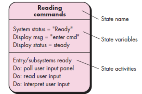
Fig 6: State diagram notation
The Behavioral model was created to help us understand the behavior of a system and the elements that drive it. A diagram is used to illustrate and represent the behavior of a system. State Transition Diagram is the name for this diagram. It consists of a series of states and events. It usually specifies the overall states that a system can have as well as the events that cause a change in status.
So, when a specific event occurs, an action is taken, and the action that needs to be made is represented by the State Transition Diagram.
Example:
Consider the use of an elevator. This elevator has n buttons, one for each floor, and serves a number of floors.
The operation of an elevator can be explained as follows:
● Elevator buttons are a sort of button that can be found on an elevator. "Elevator buttons" for that particular floor are pressed in order to reach that particular floor. When you press the "elevator buttons," the elevator will light up and begin travelling towards the floor for which you pressed the "elevator buttons." When the elevator reaches that floor, the illumination is turned off.
● Elevator floor buttons are a different type of set of buttons. When a person is on one floor and wishes to move to another, he presses the elevator button for that floor. The procedure will then be the same as described above. When you press the button, the illumination and elevator will begin to move, and when it reaches the specified floor, the illumination will be turned off.
● When an elevator is not requested, it remains closed on the current floor.
The following is a state transition diagram for an elevator system —
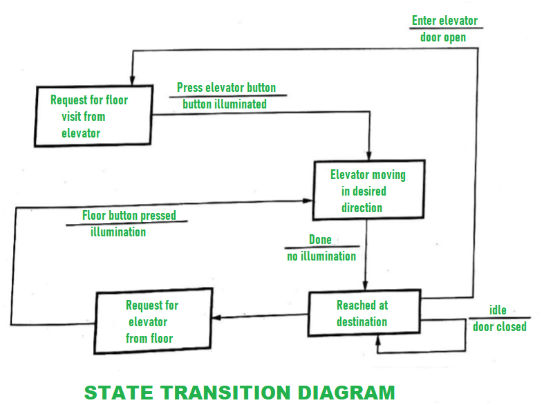
Fig 6: State transition diagram
Advantages:
● A system's behaviour and operation can be easily understood with little effort.
● Using this methodology, the results are more accurate.
● Because the cost of resources is low, this model has a lower development cost.
● It focuses on system behaviour rather than theory.
Disadvantages:
● Because this model lacks a theory, the trainee will be unable to grasp the basic principles and major concepts of modelling.
● This modelling isn't possible to automate completely.
● It can be difficult to comprehend the whole result at times.
● Due to technological faults or glitches, does not achieve full productivity.
Key takeaway
The Behavioral model was created to help us understand the behavior of a system and the elements that drive it. A diagram is used to illustrate and represent the behavior of a system. State Transition Diagram is the name for this diagram
Throughout the history of software engineering, design principles have evolved. Each principle provides a basis for the software designer from which more advanced methods of design can be implemented. Below is a brief description of essential principles in software design that encompass both conventional and object-oriented software creation.
Abstraction
When you consider every problem to be a modular solution, several levels of
Abstraction may be posed. At the highest level of abstraction, using the language of the problem setting, a solution is described in general terms. A more detailed explanation of the solution is provided at lower levels of abstraction. Finally, the solution is described in a way that can be explicitly applied at the lowest level of abstraction.
A procedural abstraction relates to a set of instructions that have a particular and restricted purpose. These functions are indicated by the name of a procedural abstraction, but precise specifics are suppressed. A data abstraction is a set of named data representing a data object.
Key takeaway:
● A procedural abstraction relates to a set of instructions that have a particular and restricted purpose.
Design Patterns
A pattern is a so-called insight nugget that transmits the essence of a known in a certain context, in the midst of conflicting problems, solutions to a recurrent problem. Stated
A design pattern defines a design framework that addresses a specific design problem within a particular context and in the midst of "forces" that may influence the way the pattern is implemented and used.
Each design pattern is intended to provide a definition that helps a designer to decide
- If the pattern applies to the current job is
- If they can reuse the pattern (hence, saving design time)
- If the model may serve as a guide to creating a pattern that is similar, but functionally or structurally different.
Key takeaway:
● A design model systematically names, motivates, and demonstrates a general design that solves a recurring design issue in object-oriented systems.
Modularity
The most common manifestation of separation of worries is modularity.
Software is split into separately named and addressable components that are combined to fulfill problem requirements, also called modules.
Modularity is the single attribute of software that enables a programme to be intellectually manageable," it has been stated." The number of paths of management, reference period, number of variables, and overall complexity will make comprehension almost impossible. You should split the design into several modules in almost all situations, aiming to make comprehension simpler and, as a result, reduce the cost of creating the programme.
Key takeaway:
● Modularity is the single attribute of software that enables a programme to be intellectually manageable.
● You should split the design into several modules.
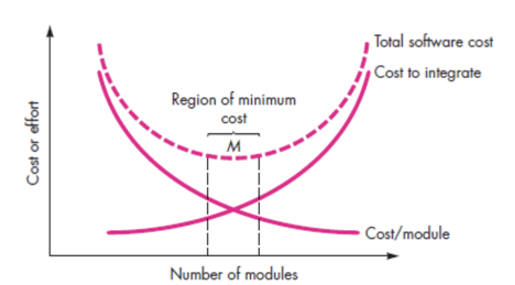
Fig 7: Modularity
Information Hiding
The theory of hiding information implies that modules are "Characterized by design decisions that hide from everyone else." In other words, modules should be defined and configured so that information stored within a module (algorithms and data) is inaccessible to other modules that do not require such information.
Hiding means that it is possible to achieve successful modularity by specifying a series of independent modules that interact with each other only with the information required to achieve software functionality.
Abstraction helps describe the groups that make up the software that are procedural (or informational). Hiding defines and enforces access restrictions within a module and any local data structure used by the module for both procedural information.
Key takeaway:
● Hiding information implies that modules are "Characterized by design decisions that hide from everyone else.
● Perhaps the most significant intellectual method built to help software design is knowledge hiding.
● Provides the fundamental inspiration for languages of the abstract data form (ADT)
Design Classes
You can identify a collection of design classes as the design model evolves,
By providing design specifics that will allow the classes to be implemented, and implementing a software infrastructure that supports the business solution, they refine the study classes.
It is possible to create five different categories of design classes, each representing a different layer of design architecture.
User interface classes - All abstractions that are required for human computer interaction are specified by user interface classes (HCI). HCI exists in certain instances within the context of a metaphor (e.g. a cheque book, an order form, a fax machine), and the interface design classes can be visual representations of the metaphor components.
Business domain classes - Sometimes, business domain classes are refinements of the classes of study. The classes specify the attributes and services (methods) needed to implement a certain business domain component.
Process classes - Lower-level business abstractions needed to handle the business domain classes completely are implemented by process classes.
Persistent classes - Persistent classes describe stores of data (e.g. a database) that will survive after the programme execution.
System classes - System classes incorporate programme management and control functions that allow the system to run and interact with the outside world and within its computing environment.
They describe four features of a well-formed class of design:
● Complete and sufficient
● Primitiveness
● High cohesion
● Low coupling
Key takeaway:
● By supplying design information, a set of design classes refined the research class.
● You can identify a collection of design classes as the design model evolves.
Refactoring
For several agile processes, a significant design task is the refactoring of a Technique of reorganization that simplifies a component's design (or code) without modifying its purpose or behavior. "Refactoring is the process of modifying a software system in such a way that it does not change the code [design]’s behavior, but improves its internal structure."
The current design is checked for duplication, unused design components, ineffective or redundant algorithms, improperly designed or inadequate data structures, or some other design flaw that can be changed to create a better design when software is refactored. The effect would be software that is easier to integrate, easier to evaluate, and easier to manage.
References:
- Software Engineering‐A Practitioner’s Approach (Sixth Edition)‐Roger Pressman (TMH)
- Software Engineering (Ninth Edition)‐Ian Sommerville (Pearson Education)
- Software Project Management ‐ Sanjay Mohapatra (Cengage Learning)
- Quantitive techniques in project management byRettyvellayudam
Unit - 3
System Analysis
Software analysis and design includes all activities, which help the transformation of requirement specification into implementation. Requirement specifications specify all functional and non-functional expectations from the software. These requirement specifications come in the shape of human readable and understandable documents, to which a computer has nothing to do.
Software analysis and design is the intermediate stage, which helps human-readable requirements to be transformed into actual code.
Structured Analysis (SA) is a diagrammatic notation for assisting people in comprehending a system. SA's main purpose is to improve quality while lowering the risk of system failure. It establishes detailed management specifications as well as supporting documentation. It emphasizes on the system's solidity, pliability, and maintainability.
The Data Flow Diagram is the foundation of SA's strategy. The SA approach is simple to grasp, yet it concentrates on a well-defined system boundary, whereas the JSD approach is overly complex and lacks a graphical depiction.
SAD is a combination of SA/SD and SAD that focuses on the following three points:
● System
● Process
● Technology
The following are the primary steps in the structured analysis process:
● Examining the current business climate.
● Creating a model of the ancient logical system.
● Creating a new logical system to model.
● Creating a new physical environment to model.
● Alternatives are being assessed.
● Choosing the most appropriate design.
● Developing well-organized specs.
Structured analysis can be viewed from three perspectives:
● Functional View - Data flow diagrams define the work that has been done and the flow of data between the things that have been done, providing the basic structure of a solution.
● Data View - The entity relationship diagram is included in the Data View, which is concerned with what exists outside the system that is being monitored.
● Dynamic View - This view includes state transition diagrams and specifies when and under what conditions things happen.
Structured Analysis Tools
For system development, Structured Analysis employs a variety of tools and approaches. They are -
● Data Flow Diagrams
● Data Dictionary
● Decision Trees
● Decision Tables
● Structured English
● Pseudocode
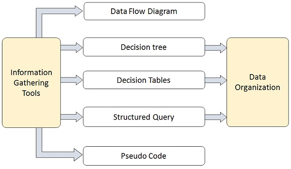
Fig 1: Tools
Key takeaway
Structured Analysis (SA) is a diagrammatic notation for assisting people in comprehending a system. SA's main purpose is to improve quality while lowering the risk of system failure.
For a computer-based system, there are several different ways of looking at the specifications. Different representation types compel you to consider criteria from multiple points of view, an approach that is more likely to expose omissions, contradictions, and uncertainty.
Scenario based modeling
From the user's perspective, the system is represented using a Scenario-based methodology. Basic use cases and their accompanying use-case diagrams, for instance, develop into more elaborate use cases based on models.
The first component of the model that is developed is mostly scenario-based elements of the requirements model. Three stages of elaboration are shown, resulting in a representation based on scenarios.
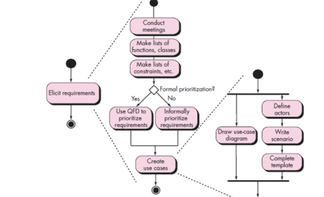
Fig 2: Activity diagram for Eliciting
Class based modeling
Each scenario of use involves a selection of artifacts that are manipulated as an actor communicates with the device. Such artifacts are grouped into groups, a group of items with similar characteristics and common behaviors.
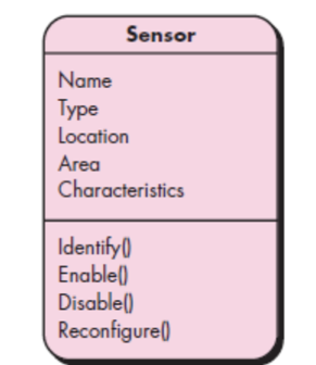
Fig 3: Class diagram for sensor
Flow oriented modeling
As knowledge flows through a computer-based system, it converts. In a variety of forms, the machine receives input, applies functions to transform it, and generates output in a variety of forms.
A control signal transmitted by a transducer can be the input, a number series typed by a human operator, an information packet transmitted over a network connection, or a voluminous data file retrieved from secondary storage.
A single logical comparison, a complex numerical algorithm, or an expert system's rule-inference approach can comprise the transform(s).
Key takeaway:
The first component of the model that is developed is mostly scenario-based elements of the requirements mode
Each scenario of use involves a selection of artifacts that are manipulated as an actor communicates with the device.
In a variety of forms, the machine receives input, applies functions to transform it, and generates output in a variety of forms.
Model specifications must have modeling components that reflect behavior.
It’s a structured method for analyzing, designing a system by applying the object-oriented concepts, and developing a set of graphical system models during the development life cycle of the software.
Object Oriented Analysis (OOA) is the first technical activity performed as part of object oriented software engineering. OOA introduces new concepts to investigate a problem. It is based in a set of basic principles, which are as follows-
- The information domain is modeled.
- Behavior is represented.
- Function is described.
- Data, functional, and behavioral models are divided to uncover greater detail.
- Early models represent the essence of the problem, while later ones provide implementation details.
The system requirements are specified, the classes are recognised, and the links between classes are identified during the system analysis or object-oriented analysis phase of software development.
Object modeling, dynamic modeling, and functional modeling are the three analysis methodologies used in conjunction for object-oriented analysis.
Object Modelling
Object modeling builds the software system's static structure in terms of objects. It specifies the objects, as well as the classes into which they can be classified and the relationships between them. It also identifies the main characteristics and operations that each class has.
The following steps can be used to visualize the object modeling process:
● Identify objects and group into classes
● Identify the relationships among classes
● Create user object model diagram
● Define user object attributes
● Define the operations that should be performed on the classes
● Review glossary
Dynamic Modelling
After analyzing the system's static behavior, it's necessary to look at its behavior in relation to time and external changes. This is what dynamic modelling is for.
"A technique of defining how an individual object responds to events, either internal events generated by other objects, or external events triggered by the outside world," according to Dynamic Modelling.
The following steps can be used to visualize the dynamic modelling process:
● Identify states of each object
● Identify events and analyze the applicability of actions
● Construct dynamic model diagram, comprising of state transition diagrams
● Express each state in terms of object attributes
● Validate the state–transition diagrams drawn
Functional Modelling
The ultimate step in object-oriented analysis is functional modelling. The functional model depicts the internal activities of an object, as well as how data changes as it flows between procedures. It defines the definition of object modelling operations as well as dynamic modelling activities. The data flow diagram of classical structured analysis conforms to the functional model.
The following steps can be used to visualize the functional modelling process:
● Identify all the inputs and outputs
● Construct data flow diagrams showing functional dependencies
● State the purpose of each function
● Identify constraints
● Specify optimization criteria
Advantages
● In contrast to Structured Analysis, it focuses on data rather than techniques.
● Encapsulation and data hiding principles assist the developer in creating systems that cannot be tampered with by other portions of the system.
● Encapsulation and data hiding principles assist the developer in creating systems that cannot be tampered with by other portions of the system.
● Because of its modularity, it provides for effective management of programme complexity.
● It can be upgraded more easily from small to large systems than systems based on structured analysis.
Disadvantages
● Within objects, functionality is limited. This could be a concern for systems that are procedural or computational in their core.
● It is unable to determine which objects would result in the best system design.
● The communications between the objects in the system are difficult to depict in object-oriented models.
● All of the object interfaces are too many to be depicted in a single diagram.
Key takeaway
Object Oriented Analysis (OOA) is the first technical activity performed as part of object oriented software engineering. OOA introduces new concepts to investigate a problem.
From the user's perspective, the system is represented using a Scenario-based methodology. Basic use cases and their accompanying use-case diagrams, for instance, develop into more elaborate use cases based on models.
The first component of the model that is developed is mostly scenario-based elements of the requirements model. Three stages of elaboration are shown, resulting in a representation based on scenarios.
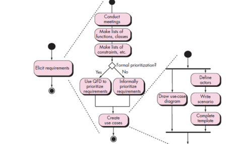
Fig 4: Activity diagram for Eliciting
As knowledge flows through a computer-based system, it converts. In a variety of forms, the machine receives input, applies functions to transform it, and generates output in a variety of forms.
A control signal transmitted by a transducer can be the input, a number series typed by a human operator, an information packet transmitted over a network connection, or a voluminous data file retrieved from secondary storage.
A single logical comparison, a complex numerical algorithm, or an expert system's rule-inference approach can comprise the transform(s).
Flow oriented modelling depicts the transformation of data objects as they move through the system. Flow models employ the data flow diagram, a modelling language that represents how input is turned into output as data items move through the system, and are derived from structured analysis. A process definition or narrative describes each software function that transforms data. This modelling feature also illustrates control flow in addition to data flow.
Although some software engineers consider flow oriented modelling to be an old approach, it is nonetheless one of the most extensively used requirements analysis notations today. Flow oriented modelling is a top-down paradigm that focuses on structured analysis and design. It uses a graphical tool to describe information flows and the transformations that are applied as data moves from input to output.
Context diagrams, data flow diagrams, entity relationship diagrams, control flow diagrams, state transition diagrams, data dictionary, process definition, and control specification are some of the modelling tools used to create a data flow oriented model. Although the data flow diagram (DFD) and related diagrams and information are not part of the UML (Unified Modeling Language), they can be used to supplement UML diagrams and provide further insight into system needs and flow. The input-process-output view of a system is used in flow oriented modelling. That is, data objects flow into the software, are transformed by processing elements, and resultant data objects flow out of the software.
Key takeaway
Flow oriented modelling depicts the transformation of data objects as they move through the system. Flow models employ the data flow diagram, a modelling language that represents how input is turned into output as data items move through the system, and are derived from structured analysis.
The objects that the system will manipulate, the operations that will be done to the objects to accomplish the manipulation, the relationships between the objects, and the collaborations that will occur between the defined classes are all represented by class-based modelling. Classes and objects, attributes, actions, class responsibility, collaborator (CRC) models, collaboration diagrams, and packages are all part of a class based model.
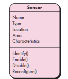
Fig 5: Class diagram for sensor
A stage of requirements modelling is class-based modelling. Requirements modelling, in the context of software engineering, looks at the requirements that a proposed software application or system must meet in order to be successful. Typically, requirements modelling starts with scenario-based modelling, which creates a use case that aids in the subsequent stages, such as data and class-based modelling. Class-based modelling pulls the classes, properties, and operations that the application will use from the use case. The end result of class-based modelling, like all modelling stages, is usually a diagram or sequence of diagrams, most commonly constructed using UML, or Unified Modeling Language.
Example Use Case
Let's pretend scenario-based modelling has already been finished and resulting in the following use case to better understand what class-based modelling entails: Sunny Beach Hotel purchases an advertisement in Acme Publishing's "Best Hotels" travel book. Acme Publishing is the client for the software development project, and they've asked for an application to manage the entire publishing process, from selling an advertisement to a client to developing the book's content to printing, shipping, and selling the book.
Class-Based Model Method
The first step in class-based modelling is to identify the classes in the use case.
Performing a grammatical parse of the problem statement or use case is one technique to uncover potential analysis classes. This is accomplished by underlining each noun or noun clause in the problem statement or use case, but leaving verbs out.
The following is a grammatical parse of the example use case (please note that certain nouns, which are ordinarily underlined, are bolded):
Sunny Beach Hotel purchases an advertisement in Acme Publishing's "Best Hotels" travel book.
After that, class-based modelling employs a number of general categories to aid in the identification of elements that may be classified as possible classes:
● External entities that generate or consume data that the programme can use (in the example use case, Sunny Beach Hotel)
● Things that are part of the problem's information domain (the advertisement that Sunny Beach Hotel purchases)
● Occurrences are events that occur during the operation of a system (the transaction of Sunny Beach Hotel purchasing the advertisement from Acme Publishing)
● People who interact with the system perform various roles (the marketing representative at Sunny Beach Hotel that places the order for the advertisement with Acme Publishing and the salesperson at Acme Publishing that receives the order)
● Units of an organization that are relevant to an application (divisions, groups or teams, like the sales and editorial departments at Acme Publishing)
● Locations that establish the problem's context and the system's general function (Sunny Beach Hotel's location; Acme Publishing's headquarters location).
● Structures that specify a class of objects or related classes of objects ("Best Hotels" is one of several travel books published by Acme Publishing, therefore "travel book" is a class of objects in this context.)
Key takeaway
Classes and objects, attributes, actions, class responsibility, collaborator (CRC) models, collaboration diagrams, and packages are all part of a class based model.
A computer-based system's actions can have a profound impact on the chosen specification and the approach to implementation that is implemented. Therefore, model specifications must have modelling components that reflect behaviour.
One way to describe a system's actions by describing its states and the events that cause the system to change its state is the state diagram. Any externally measurable mode of action is a state.
Furthermore, as a result of a specific incident, the state diagram shows actions taken.
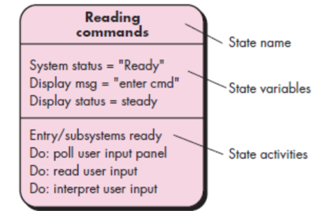
Fig 6: State diagram notation
The Behavioral model was created to help us understand the behavior of a system and the elements that drive it. A diagram is used to illustrate and represent the behavior of a system. State Transition Diagram is the name for this diagram. It consists of a series of states and events. It usually specifies the overall states that a system can have as well as the events that cause a change in status.
So, when a specific event occurs, an action is taken, and the action that needs to be made is represented by the State Transition Diagram.
Example:
Consider the use of an elevator. This elevator has n buttons, one for each floor, and serves a number of floors.
The operation of an elevator can be explained as follows:
● Elevator buttons are a sort of button that can be found on an elevator. "Elevator buttons" for that particular floor are pressed in order to reach that particular floor. When you press the "elevator buttons," the elevator will light up and begin travelling towards the floor for which you pressed the "elevator buttons." When the elevator reaches that floor, the illumination is turned off.
● Elevator floor buttons are a different type of set of buttons. When a person is on one floor and wishes to move to another, he presses the elevator button for that floor. The procedure will then be the same as described above. When you press the button, the illumination and elevator will begin to move, and when it reaches the specified floor, the illumination will be turned off.
● When an elevator is not requested, it remains closed on the current floor.
The following is a state transition diagram for an elevator system —
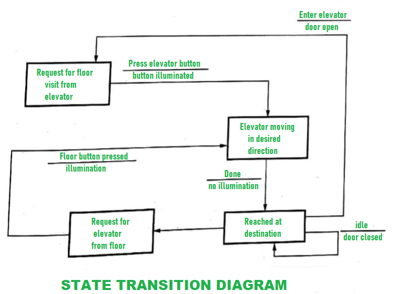
Fig 6: State transition diagram
Advantages:
● A system's behaviour and operation can be easily understood with little effort.
● Using this methodology, the results are more accurate.
● Because the cost of resources is low, this model has a lower development cost.
● It focuses on system behaviour rather than theory.
Disadvantages:
● Because this model lacks a theory, the trainee will be unable to grasp the basic principles and major concepts of modelling.
● This modelling isn't possible to automate completely.
● It can be difficult to comprehend the whole result at times.
● Due to technological faults or glitches, does not achieve full productivity.
Key takeaway
The Behavioral model was created to help us understand the behavior of a system and the elements that drive it. A diagram is used to illustrate and represent the behavior of a system. State Transition Diagram is the name for this diagram
Throughout the history of software engineering, design principles have evolved. Each principle provides a basis for the software designer from which more advanced methods of design can be implemented. Below is a brief description of essential principles in software design that encompass both conventional and object-oriented software creation.
Abstraction
When you consider every problem to be a modular solution, several levels of
Abstraction may be posed. At the highest level of abstraction, using the language of the problem setting, a solution is described in general terms. A more detailed explanation of the solution is provided at lower levels of abstraction. Finally, the solution is described in a way that can be explicitly applied at the lowest level of abstraction.
A procedural abstraction relates to a set of instructions that have a particular and restricted purpose. These functions are indicated by the name of a procedural abstraction, but precise specifics are suppressed. A data abstraction is a set of named data representing a data object.
Key takeaway:
● A procedural abstraction relates to a set of instructions that have a particular and restricted purpose.
Design Patterns
A pattern is a so-called insight nugget that transmits the essence of a known in a certain context, in the midst of conflicting problems, solutions to a recurrent problem. Stated
A design pattern defines a design framework that addresses a specific design problem within a particular context and in the midst of "forces" that may influence the way the pattern is implemented and used.
Each design pattern is intended to provide a definition that helps a designer to decide
- If the pattern applies to the current job is
- If they can reuse the pattern (hence, saving design time)
- If the model may serve as a guide to creating a pattern that is similar, but functionally or structurally different.
Key takeaway:
● A design model systematically names, motivates, and demonstrates a general design that solves a recurring design issue in object-oriented systems.
Modularity
The most common manifestation of separation of worries is modularity.
Software is split into separately named and addressable components that are combined to fulfill problem requirements, also called modules.
Modularity is the single attribute of software that enables a programme to be intellectually manageable," it has been stated." The number of paths of management, reference period, number of variables, and overall complexity will make comprehension almost impossible. You should split the design into several modules in almost all situations, aiming to make comprehension simpler and, as a result, reduce the cost of creating the programme.
Key takeaway:
● Modularity is the single attribute of software that enables a programme to be intellectually manageable.
● You should split the design into several modules.
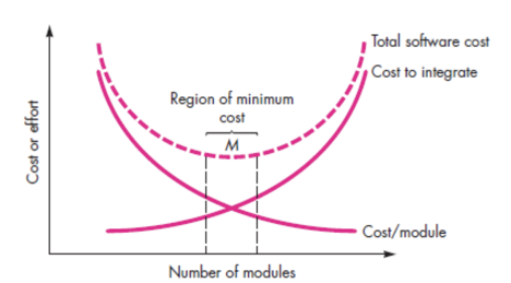
Fig 7: Modularity
Information Hiding
The theory of hiding information implies that modules are "Characterized by design decisions that hide from everyone else." In other words, modules should be defined and configured so that information stored within a module (algorithms and data) is inaccessible to other modules that do not require such information.
Hiding means that it is possible to achieve successful modularity by specifying a series of independent modules that interact with each other only with the information required to achieve software functionality.
Abstraction helps describe the groups that make up the software that are procedural (or informational). Hiding defines and enforces access restrictions within a module and any local data structure used by the module for both procedural information.
Key takeaway:
● Hiding information implies that modules are "Characterized by design decisions that hide from everyone else.
● Perhaps the most significant intellectual method built to help software design is knowledge hiding.
● Provides the fundamental inspiration for languages of the abstract data form (ADT)
Design Classes
You can identify a collection of design classes as the design model evolves,
By providing design specifics that will allow the classes to be implemented, and implementing a software infrastructure that supports the business solution, they refine the study classes.
It is possible to create five different categories of design classes, each representing a different layer of design architecture.
User interface classes - All abstractions that are required for human computer interaction are specified by user interface classes (HCI). HCI exists in certain instances within the context of a metaphor (e.g. a cheque book, an order form, a fax machine), and the interface design classes can be visual representations of the metaphor components.
Business domain classes - Sometimes, business domain classes are refinements of the classes of study. The classes specify the attributes and services (methods) needed to implement a certain business domain component.
Process classes - Lower-level business abstractions needed to handle the business domain classes completely are implemented by process classes.
Persistent classes - Persistent classes describe stores of data (e.g. a database) that will survive after the programme execution.
System classes - System classes incorporate programme management and control functions that allow the system to run and interact with the outside world and within its computing environment.
They describe four features of a well-formed class of design:
● Complete and sufficient
● Primitiveness
● High cohesion
● Low coupling
Key takeaway:
● By supplying design information, a set of design classes refined the research class.
● You can identify a collection of design classes as the design model evolves.
Refactoring
For several agile processes, a significant design task is the refactoring of a Technique of reorganization that simplifies a component's design (or code) without modifying its purpose or behavior. "Refactoring is the process of modifying a software system in such a way that it does not change the code [design]’s behavior, but improves its internal structure."
The current design is checked for duplication, unused design components, ineffective or redundant algorithms, improperly designed or inadequate data structures, or some other design flaw that can be changed to create a better design when software is refactored. The effect would be software that is easier to integrate, easier to evaluate, and easier to manage.
References:
- Software Engineering‐A Practitioner’s Approach (Sixth Edition)‐Roger Pressman (TMH)
- Software Engineering (Ninth Edition)‐Ian Sommerville (Pearson Education)
- Software Project Management ‐ Sanjay Mohapatra (Cengage Learning)
- Quantitive techniques in project management byRettyvellayudam