Unit - 1
Lasers & Wave Optics
The laser light exhibits some peculiar properties compare with the conventional light. Those are
1. Highly monochromatic
2. Highly coherence
3. Highly directionality
4. Highly intense
5. Laser Speckles
1. Highly monochromatic
Monochromatic light means a light containing a single colour or wavelength. The photons emitted from ordinary light sources have different energies, frequencies, wavelengths, or colours. Ordinary light is a mixture of waves having different frequencies or wavelengths. The light waves of laser have a single wavelength or colour.
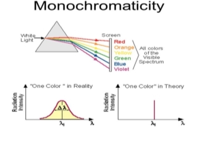
Figure 1: Monochromatic
Therefore, laser light covers a very narrow range of frequencies or wavelengths.
Hence The laser light is more monochromatic than that of a conventional light source. This may be due to the stimulated characteristic of laser light. The bandwidth of the conventional monochromatic light source is 1000 Å. But the bandwidth of an ordinary light source is 10 Å. For high sensitive laser source is 10-8 Å.


Figure 2: Intensity- wavelength graph for light and laser
2. Highly coherence
Definition: - A predictable correlation of the amplitude and phase at any one point with another point is called coherence.
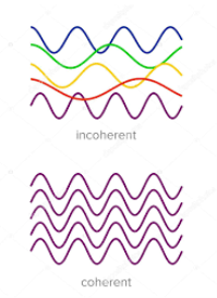
Figure 3: Incoherence and coherence
Two waves are said to be coherent, the waves must have
In the case of conventional light, the property of coherence exhibits between a source and its virtual source whereas in the case of laser the property coherence exists between any two or more light waves.
There are two types of coherence
- Temporal coherence
- Spatial coherence
Temporal coherence (or longitudinal coherence):
The predictable correlation of amplitude and phase at one point on the wave train w. r. At another point on the same wave train, then the wave is said to be temporal coherence
To understand this, let us consider two points P1 and P2 on the same wave train, which is continuous as shown in the figure.

Figure 4: Wave train
Suppose the phase and amplitude at any one point is known, then we can easily calculate the amplitude and phase for any other point on the same wave train by using the wave equation
y= a sin (  (ct-x))
Where ‘a’ is the amplitude of the wave and ‘x’ is the displacement of the wave at any instant of time ‘t’.
Spatial coherence (or transverse coherence) The predictable correlation of amplitude and phase at one point on the wave train w. r. t another point on a second wave, then the waves are said to be spatial coherence (or transverse coherence)
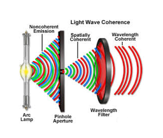
Figure 5: Spatial coherence
3. Highly directionality
The light ray coming from an ordinary light source travels in all directions, but laser light travels in a single direction. For example, the light emitted from torchlight spreads 1km distance it spreads 1 km distance. But the laser light spreads a few centimetres distance even it travels lacks kilometre distance.
The directionality of the laser beam is expressed in terms of divergence

Where r1 and r2 are the radii of laser beam spots at distances of D1 and D2 respectively from the laser source.
4. Highly Intense or Brightness
We know that the intensity of a wave is the energy per unit time flowing through a unit's normal area. Laser light is highly intense than conventional light. A one mill watt He-Ne laser is highly intense than the sun intensity. This is because of the coherence and directionality of the laser. Suppose when two photons each of amplitude a are in phase with other, then young’s principle of superposition, the resultant amplitude of two photons is 2a and the intensity is 4a2. Since in laser many numbers of photons are in phase with each other, the amplitude of the resulting wave becomes na and hence the intensity of the laser is proportional to n2a2. So 1mW He-Ne laser is highly intense than the sun.
In an ordinary light source, the light spreads out uniformly in all directions. If you look at a 100 Watt lamp filament from a distance of 30 cm, the power entering your eye is less than 1/1000 of a watt. If you look at laser beam X (caution: don’t do it at home, direct laser light can damage your eyes) X, then all the power in the laser would enter your eye. Thus, even a 1 Watt laser would appear many thousand times more intense than a 100 Watt ordinary lamp.
5. Laser Speckles
The term speckle refers to a random granular pattern that can be observed when a highly coherent light beam is diffusely reflected at a surface with a complicated structure. This phenomenon results from the interference of different reflected portions of the incident beam with random relative optical phases.
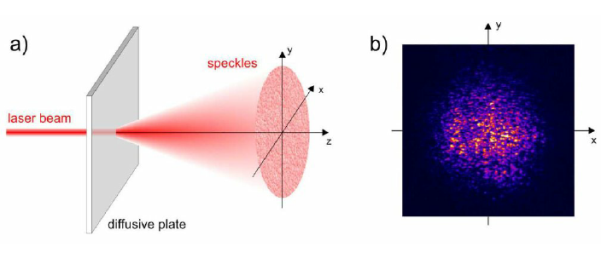
Figure 6: Laser Speckles
Even minor changes of the conditions, such as of the illuminated spot or the direction of the incident laser beam, can change the detailed shape of a speckle pattern.
When laser light that has been scattered off a rough surface falls on another surface, it forms an "objective speckle pattern". If a photographic plate or another 2-D optical sensor is located within the scattered light field without a lens, a speckle pattern is obtained whose characteristics depend on the geometry of the system and the wavelength of the laser.
Key Takeaways
- The laser light exhibits some peculiar properties compare with the conventional light. Laser light is highly monochromatic, coherence, directionality, intense and Laser Speckles.
- A predictable correlation of the amplitude and phase at any one point with another point is called coherence.
- There are two types of coherence: Temporal coherence and Spatial coherence.
- The directionality of the laser beam is expressed in terms of divergence

- The intensity of a wave is the energy per unit time flowing through a unit's normal area.
Let us discuss Einstein’s theory of interaction of electromagnetic radiation with matter. He proposed that electromagnetic radiation interacts with matter in following three steps.
- Stimulated Absorption
- Spontaneous Emission
- Stimulated Emission
Stimulated Absorption:
Let E1 and E2 be the energies of ground and excited states of an atom. Suppose, if a photon of energy hν= E1− E2 interacts with an atom present in the ground state, the atom gets excitation form ground state E1 to excited state E2. This process is called stimulated absorption. Stimulated absorption rate depends upon the number of atoms available in the lowest energy state as well as the energy density photons.
Stimulated absorption rate ∝ Number of atoms in the ground state
∝ Density of photons Spontaneous emission
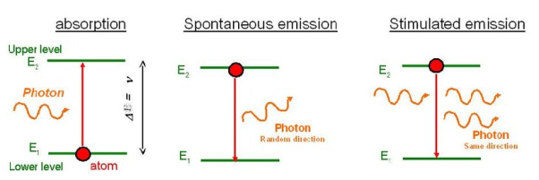
Figure:7
Spontaneous Emission:
Let E1 and E2 be the energies of ground and excited states of an atom. Suppose, if a photon of energy hν= E1− E2 interacts with an atom present in the ground state, the atom gets excitation form ground stateE1 to excited state E2. The excited atom does not stay in a long time in the excited state. The excited atom gets de-excitation after its life time by emitting a photon of energy hν= E1− E2. This process is called spontaneous emission. Also Spontaneous means by its own. Here excited atom comes to ground state by its own so it is named as spontaneous emission.
The spontaneous emission rate depends up on the number of atoms present in the excited state.
Spontaneous emission ∝ rate number of atoms in the excited state
Spontaneous emission is an energy conversion process in which an excited electron or molecule decays to an available lower energy level and in the process gives off a photon. This process occurs naturally and does not involve interaction of other photons. The average time for decay by spontaneous emission is called the spontaneous emission lifetime. For some excited energy levels this spontaneous decay occurs on average within nanoseconds while in other materials it occurs within a few seconds. As with absorption, this process can occur in isolated atoms, ionic compounds, molecules, and other types of materials, and it can occur in solids, liquids, and gases. Energy is conserved when the electron decays to the lower level, and that energy must go somewhere. The energy may be converted to heat, mechanical vibrations, or electromagnetic photons. If it is converted to photons, the process is called spontaneous emission, and the energy of the photon produced is equal to the energy deference between the electron energy levels involved. The emitted photon may have any direction, phase, and electromagnetic polarization.
There are many ways in which an electron can be excited to a higher energy level. Spontaneous emission processes may be classified based on the source of energy which excites the electrons. If the initial source of energy for spontaneous emission is supplied optically, the process is called photoluminescence. Glow in the dark materials emit light by this process. If the initial form of energy is supplied by a chemical reaction, the process is called chemiluminescence. Glow sticks produce spontaneous emission by chemiluminescence. If the initial form of energy is supplied by a voltage, the process is called electroluminescence. LEDs emit light by electroluminescence. If the initial form of energy is caused by sound waves, the process is called sonoluminescence. If the initial form of energy is due to accelerated electrons hitting a target, this process is called cathodoluminescence. If spontaneous emission occurs in a living organism, such a firefly, the process is called bioluminescence.
Stimulated Emission:
This phenomenon is responsible for producing laser light. Let E1and E2 be the energies of ground and excited states of an atom. Suppose, if a photon of energy hν= E1− E2 interacts with an atom present in the ground state, the atom gets excitation form ground stateE1 to excited state E2. Let, a photon of energy hν= E1− E2 interacts with the excited atom with in their life time; the atom gets de-excitation to ground state by emitting of another photon. These photons have same phase and it follows coherence. This phenomenon is called stimulated emission.
Stimulated emission rate depends upon the number of atoms available in the excited state as well as the energy density of photons.
Stimulated emission rate ∝ number of atoms in the excited state
∝ Density of photons
Stimulated emission is the process in which an excited electron or molecule interacts with a photon, decays to an available lower energy level, and in the process gives o a photon. As with the other processes, this process can occur in isolated atoms, ionic compounds, organic molecules, and other types of materials, and it can occur in solids, liquids, and gases. If an incoming photon, with energy equal to the difference between allowed energy levels, interacts with an electron in an excited state, stimulated emission can occur. The energy of the excited electron will be converted to the energy of a photon. The stimulated photon will have the same frequency, direction, phase, and electromagnetic polarization as the incoming photon which initiated the process

Metastable states also play some important and key roles in gas lasers:
- In a number of gas lasers, helium atoms are excited into metastable states by an electrical discharge. During collisions with other atoms (e.g. Neon in a helium-neon laser), they can then transfer or exchange the excitation energy to those atoms. Efficient resonant energy exchange requires that the excitation energies of the two species are quite similar i.e., metastable equilibrium. That condition is absent in the case of Penning ionization because that leads to a free electron that can move away a variable amount of energy. That happens in helium–cadmium lasers, for example.
- It also occurs that after the laser transition atoms are trapped in a metastable state (metastable ions). That is the case in helium-neon lasers, for example. Here, it is a good solution to use a laser bore tube with a considerably small diameter, so that the metastable atoms can dissipate (release) their energy in collisions with the tube wall. Only thereafter, they can again participate in the lasing action.
Lasers Without Metastable States
Generally, laser gain media do not have to exhibit metastable levels, it is a short-lived level that can still be used as the higher (or the excited) laser level provided that the emission cross-sections are large enough. (For the threshold pump power, the σ−τ product is the essential quantity.) However, long metastable level lifetimes are very important for Q-switched lasers, as they permit significant energy storage. They also have a strong impact on laser dynamics, including spiking phenomena. Finally, three-level laser transitions are hardly possible without metastable levels, since a substantial upper-state population as needed for positive net gain would be difficult to achieve.
In laser modelling of doped-insulator solid-state lasers, one usually considers population only of metastable states and the ground state, because only a vanishingly small proportion of the laser-active ions can be in other (short-lived or metastable phase) states. This can substantially simplify laser models.
Thus, for laser action, pumping mechanism (exciting with external source) maintain a higher population of atoms in the upper energy level relative to that in the lower level.
A system in which population inversion is achieved is called as an active system. The method of raising the particles from lower energy state to higher energy state is called pumping.
The process of achieving of population inversion is called pumping.
This can be done by number of ways.
The most commonly used pumping methods are
- Optical pumping
- Electrical discharge pumping
- Chemical pumping
- Thermal Pumping
- Injection current pumping
- Inelastic Atom-Atom Collisions
Optical pumping As the name suggests, in this method, light is used to supply energy to the laser medium. Optical pumping is used in solid laser. Xenon flash tubes are used for optical pumping. Since these materials have very broad band absorption, sufficient amount of energy is absorbed from the emission band of flash lamp and population inversion is created. So xenon flash lamp is used to produce more electrons in the higher energy level of the laser medium.
Examples of optically pumped lasers are ruby, Nd: YAG Laser(Neodymium: Yttrium Aluminium Garnet).
Electrical discharge pumping Electrical discharge pumping is used in gas lasers. Since gas lasers have very narrow absorption band pumping then any flash lamp is not possible. Electric discharge refers to flow of electrons or electric current through a gas, liquid or solid.
In this method of pumping, electric discharge acts as the pump source or energy source. A high voltage electric discharge (flow of electrons, electric charge, or electric current) is passed through the laser medium or gas. The intense electric field accelerates the electrons to high speeds and they collide with neutral atoms in the gas. As a result, the electrons in the lower energy state gains sufficient energy from external electrons and jumps into the higher energy state
Examples of Electrical discharge pumped lasers are He-Ne laser, CO2 laser, argon-ion laser etc.
Chemical pumping Chemical reaction may also result in excitation and hence creation of population inversion in few systems.
If an atom or a molecule is produced through some chemical reaction and remains in an excited state at the time of production, then it can be used for pumping. The hydrogen fluoride molecule is produced in an excited state when hydrogen and fluorine gas chemically combine. The number of produced excited atoms or molecules is greater than the number of normal state atoms or molecules. Thus, population inversion is achieved.
Examples H2 + F2→ 2HF, in this chemical reaction, hydrogen (H2) and fluorine (F2) molecules are chemically combined to produce hydrogen fluoride molecule (2HF) in an excited state.
Thermal Pumping: Sometimes we can achieve population inversion by heating the laser medium. In thermal pumping, heat acts as the pump source or energy source. In this method, population inversion is achieved by supplying heat into the laser medium.
When heat energy is supplied to the laser medium, the lower energy state electrons gains sufficient energy and jumps into the higher energy level.
The process of achieving population inversion in thermal pumping is almost similar to the optical pumping or electric discharge method, except that in this method heat is used as pump source instead of light or electric discharge.
Injection current pumping In semiconductors, injection of current through the junction results in creates of population inversion among the minority charge carriers.
Examples of such systems are InP and GaAs.
Inelastic Atom-Atom Collisions: Like the electric discharge method, here also a high voltage electric discharge acts as a pump source. However, in this method, a combination of two types of gases, say X and Y are used. The excited state of gas X is represented as X+ whereas gas Y is represented as Y+. Both X and Y gases have the same excited states (X+ and Y+).
When high voltage electric discharge passes through a laser medium having two types of gases X and Y, the lower energy state electrons in gas X will move to the excited state X+ similarly the lower energy state electrons in gas Y moves to the excited state Y+.
Initially, during electric discharge, the lower energy state electrons in gas X or atom X gets excited to X+ due to continuous collision with electrons. The excited state electrons in gas X+ now collide with the lower energy state electrons in gas Y. As a result, the lower energy state electrons in gas Y gains sufficient energy and jump into the excited state Y+. This method is used in the Helium–Neon (He-Ne) laser.
The principle of laser amplification is stimulated emission.
Every LASER consists of three basic components. These are –
- Lasing material or active medium.
- External energy source.
- Optical resonator.
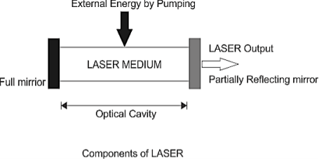
Figure 8: Components of laser
Lasing Material or Active Medium
The active medium is excited by the external energy source (pump source) to produce the population inversion. In the gain medium that spontaneous and stimulated emission of photons takes place, leading to the phenomenon of optical gain, or amplification. Semiconductors, organic dyes, gases (He, Ne, CO2, etc), solid materials (YAG, sapphire (ruby) etc.) are usually used as lasing materials and often LASERs are named for the ingredients used as a medium.
External Energy Source
The excitation source, pump source provides energy which is needed for the population inversion and stimulated emission to the system. Pumping can be done in two ways – electrical discharge method and optical method. Examples of pump sources are electrical discharges, flash lamps, arc lamps, light from another laser, chemical reactions etc.
Optical Resonator
Resonator guide basically provides the guidance about the simulated emission process. It is induced by high-speed photons. Finally, a laser beam will be generated.
In most of the systems, it consists of two mirrors. One mirror is fully reflective and other is partially reflective. Both the mirrors are set up on optic axis, parallel to each other. The active medium is used in the optical cavity between the both mirrors. This arrangement only filters those photons which came along the axis and others are reflected by the mirrors back into the medium, where it may be amplified by stimulated emission.
Key Takeaways
- Every LASER consists of three basic components. These are Lasing material or active medium, External energy source, Optical resonator.
- The active medium is excited by the external energy source (pump source) to produce the population inversion
- The excitation source, pump source provides energy which is needed for the population inversion and stimulated emission to the system.
- Resonator guide basically provides the guidance about the simulated emission process. It is induced by high-speed photons. Finally, a laser beam will be generated.
I Mono-chromaticity
Highly Monochromatic:
The light from a laser typically comes from one atomic transition with a single precise wavelength. So, the laser light has a single spectral color and is highly monochromatic light available.
II Coherence
Coherence:
The light from a laser is said to be coherent, which means that the wavelengths of the laser light are in phase in space and time. Large number of identical
photons are emitted through stimulated emission and therefore they will be in phase with each other.
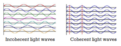
Fig.9: Coherent and Incoherent light waves
III Directionality and brightness
Highly Directional and Collimated:
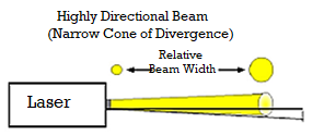
Lasers emit light that is highly directional, narrow beam divergence. The light from laser emerges in an extremely thin beam with very little divergence therefore the beam is also highly collimated. The high degree of collimation arises from the fact that the cavity of the laser has very nearly parallel front and back mirrors which constrain the final laser beam to a path which is perpendicular to those mirrors. As a result, laser beams are very narrow and do not spread very much.
Angle of divergence, Ø = 2π λ/D
Where D is diameter of beam.
IV Laser speckles
Speckle patterns can severely degrade the image quality of laser projection displays, or disturb position measurements with laser pointers. Speckle can often be avoided, e.g. By using a light source with sufficiently large optical bandwidth (short coherence length) such as a super luminescent source. (How much bandwidth is required for that purpose depends on the situation.) For projection displays, one may also work with an optimized screen. However, there are also applications of speckle, e.g. In speckle interferometry.
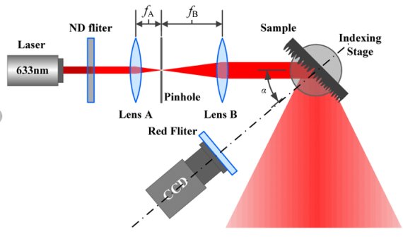
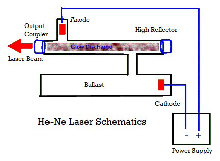
The He-Ne laser was the first invented continuous wave (cw) laser. A few months after Maiman announced his invention of the pulsed ruby laser, Ali Javan and partners W. R. Bennet and D. R. Herriott announced their creation of a He-Ne cw laser.
This gas laser is a four-level laser that uses helium atoms to excite neon atoms. It is the atomic transitions in the neon that produce laser light.
The maximum usually used neon conversion in these lasers products red light at 632.8 nm. But these lasers can also produce both visible and UV and IR green and yellow light (Javan's first He-Ne worked on IR at 1152.3 nm).
Using highly reflective mirrors designed for one of these many
possible laser transitions, a given He-Ne output is operated at a single wavelength.
He-Ne lasers generally produce a few to tens of mW (milliwatts or 10-3 W) of power. They are not high power laser light sources.
Probably one of the most important characteristics of these lasers is that they are highly stable, both in terms of wavelength (mode stability) and intensity of light output (low fluctuation in power level).
For these reasons, He-Ne lasers are often used to stabilize other lasers. They are also used in applications such as holography, where mode stability is important.
Until the mid-1990s, He-Ne lasers were the dominant type of lasers produced for low-power applications, from range search to scanning, optical transmission, laser pointers, etc. Recently, however, other types of lasers.
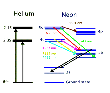
The above energy level diagram shows the two excited states of helium atom, the 2 3S and 2 1S, that get populated as a result of the electromagnetic pumping in the discharge.
Both of these states are metastable and do not allow de-excitations via radiative transitions. Instead, the helium atoms give off their energy to neon atoms through collisional excitation.
In this way the 4s and 5s levels in neon get populated. These are the two upper lasing levels, each for a separate set of lasing transitions.
Radiative decay from the 5s to the 4s levels are forbidden. So, the 4p and 3p levels serve as the lower lasing levels and rapidly decay into the metastable 3s level.
In this way population inversion is easily achieved in the He-Ne. The 632.8 nm laser transition, for example, involves the 5s and 3p levels, as shown above.
Ruby laser is a three-level solid-state laser and was constructed by Maiman in 1960. Ruby laser is one of the few solid-state lasers that produce visible light. It emits deep red light of wavelength 694.3 nm.
Construction
A ruby laser consists of three important elements: laser medium, the pump source, and the optical resonator.
Laser Medium
Ruby (Al2O3+Cr2O3) is a crystal of Aluminium oxide, in which 0.05% of Al+3 ions are replaced by the Cr+3 ions. The colour of the rod is pink. The active medium or laser medium in the ruby rod is Cr+3 ions. In ruby laser, 4cm length and 5mm diameter rod is generally used. The ruby has good thermal properties.
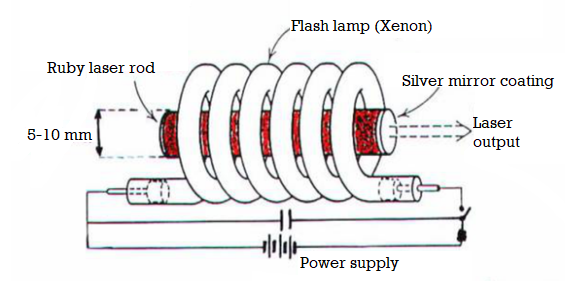
Figure 10: Ruby laser
The pump source
The ruby rod is surrounded by a xenon flash tube, which provides the pumping light to excite the chromium ions into upper energy levels. The ruby rod was surrounded by a helical xenon flash lamp.
We know that population inversion is required to achieve laser emission. Population inversion is the process of achieving a greater population of a higher energy state than the lower energy state. To achieve population inversion, we need to supply energy to the laser medium i.e. to ruby crystal.
Xenon flash tube emits thousands of joules of energy in few milliseconds, but only a part of that energy is utilized by the chromium ions while the rest energy heats the apparatus. A cooling arrangement is provided to keep the experimental set up at normal temperatures.
Optical resonator
Both the ends of the rods are highly polished and made strictly parallel. The ends are silvered in such a way, one becomes partially reflected the laser beam was emitted through that end and the other end fully reflected to reflect all the rays of light striking it.
Working of ruby laser:
Consider a ruby laser medium consisting of three energy levels E1, E2, E3 with N number of electrons.
We assume that the energy levels will be E1 < E2 < E3. The energy level E1 is known as the ground state or lower energy state, the energy level E2 is known as the metastable state, and the energy level E3 is known as the pump state.
Let us assume that initially most of the electrons are in the lower energy state (E1) and only a tiny number of electrons are in the excited states (E2 and E3).
The energy level diagram of chromium ions is shown in the figure. The chromium ions get excitation into higher energy levels by absorbing 5500Å of wavelength radiation. The excited chromium ions stay in the level E3 for a short interval of time (10-8 to 10-9 Sec). After their life, most of the chromium ions are de-excited from E3 to E1 and a few chromium ions are de-excited from E3 to E2.
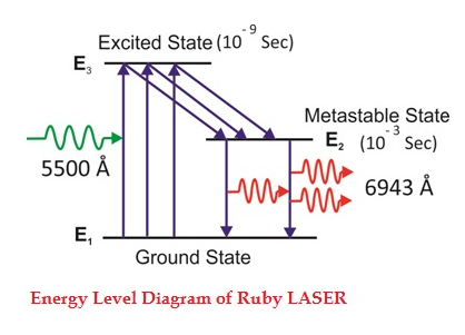
Figure 11: Energy Level diagram of ruby laser
The transition between E3 and E2 is non-radioactive i.e. the chromium ions give their energy to the lattice in the form of heat. In the Metastable state, the lifetime of chromium ions is 10-3 sec. The lifetime of chromium ions in the Metastable state is 105 times greater than the lifetime of chromium ions in a higher state.
Due to the continuous working of the flash lamp, the chromium ions are excited to a higher state E3 and returned to the E2 level. After a few milliseconds, the level E2 is more populated than the level E1 and hence the desired population inversion is achieved. The state of population inversion is not a stable one. The process of spontaneous transition is very high. When the excited chromium ion passes spontaneously from E3 to E2it emits one photon of wavelength 6943 Å. The photon reflects back and forth by the silver ends and until it stimulates an excited chromium ion in the E2 state and it to emit a fresh photon in phase with the earlier photon. The process is repeated again and again until the laser beam intensity is reached a sufficient value. When the photon beam becomes sufficiently intense, it emerges through the partially silvered end of the rod. The wavelength 6943 Å is in the red region of the visible spectrum.
Drawbacks of the ruby laser
- The laser requires high pumping power
- The efficiency of a ruby laser is very small
- It is a pulse laser
Application of ruby laser
- Ruby lasers are in optical photography
- Ruby lasers can be used for the measurement of plasma properties such as electron density and temperature.
- Ruby lasers are used to remove the melanin from the skin.
- Ruby laser can be used for the recording of holograms.
Key Takeaways
- Ruby laser is a three-level solid-state laser.
- A ruby laser consists of three important elements: laser medium, the pump source, and the optical resonator.
- Ruby laser is one of the few solid-state lasers that produce visible light. It emits deep red light of wavelength 694.3 nm.
Semiconductor Laser
It is a solid state semiconductor laser. It is specifically fabricated p-n junction diode. This diode emits laser light when it is forward biased. A semiconductor laser is a device that causes laser oscillation by flowing an electric current to semiconductor. The mechanism of light emission is the same as a light-emitting diode (LED). Light is generated by flowing the forward current to a p-n junction. In forward bias operation, the p-type layer is connected with the positive terminal and the n-type layer is connected with the negative terminal, electrons enter from the n-type layer and holes from the p-type layer. When the two meet at the junction, an electron drops into a hole and light is emitted at the time.
Semiconductor lasers represent one of the most important class of lasers in use today, not only because of the large variety of direct applications in which they are involved but also because they have found a widespread use as pumps for solid state lasers.
Semiconductor lasers require, for the active medium, a direct gap material and accordingly, the normal elemental semiconductors like Si or Ge cannot be used. The majority of semiconductor-laser materials are based on a combination of elements belonging to the third group of the periodic table such as Al, Ga, In with elements of the fifth group such as N, P,As, Sb. Examples include the best known GaAs as well as some ternary AlGaAs, InGaAs and quaternary InGaAsP alloys.
InGaN semiconductor lasers the best candidates for semiconductor laser emission in the very important blue-green spectral region. Semiconductor laser materials are not limited to III–V compounds, however. For the blue-green end of the spectrum we note that there are wide-gap semiconductors using a combination between elements of the second group (such as Cd and Zn) and of the sixth group (S, Se).
PRINCIPLE
When a p-n junction diode is forward biased, the electrons from n – region and the holes from the p- region cross the junction and recombine with each other.
During the recombination process, the light radiation (photons) is released from a certain specified direct band gap semiconductors like Ga-As. This light radiation is known as recombination radiation.
The photon emitted during recombination stimulates other electrons and holes to recombine. As a result, stimulated emission takes place which produces laser.
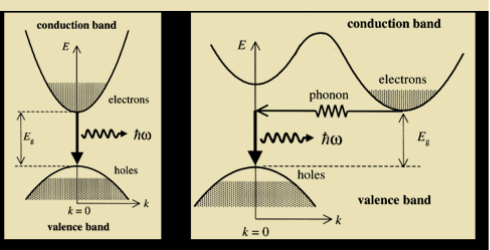
Figure 12: Semiconductor Laser
CONSTRUCTION
The basic structure of a semiconductor laser is shown in Figure. The active medium is a p-n junction diode made from the single crystal of gallium arsenide. The active layer called as light emission layer sandwiched between the p- and n-type clad layers i.e. double hetero structure is formed on an n-type substrate and voltage is applied across the p-n junction from the electrodes. This crystal is cut in the form of a platter having thickness of 0.5μmm. Both edges of the active layer has mirror-like surface. When forward voltage is applied, electrons combine with holes at the p-n junction, and emit the light.
This light is not a laser yet; it is confined within the active layer because the refractive index of the clad layers is lower than that of the active layer. In addition both ends of the active layer act as a reflecting mirror where the light reciprocates in the active layer. Then, the light is amplified by the stimulated emission process and laser oscillation is generated.
The photon emission is stimulated in a very thin layer of PN junction (in order of few microns). The electrical voltage is applied to the crystal through the electrode fixed on the upper surface. The end faces of the junction diode are well polished and parallel to each other. They act as an optical resonator through which the emitted light comes out.
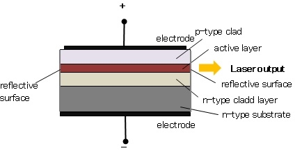
Figure 13: Construction of semiconductor Laser
WORKING
When the PN junction is forward biased with large applied voltage, the electrons and holes are injected into junction region in considerable concentration
The region around the junction contains a large amount of electrons in the conduction band and a large amount of holes in the valence band.
If the population density is high, a condition of population inversion is achieved. The electrons and holes recombine with each other and this recombination’s produce radiation in the form of light.
When the forward – biased voltage is increased, more and more light photons are emitted and the light production instantly becomes stronger. These photons will trigger a chain of stimulated recombination resulting in the release of photons in phase.
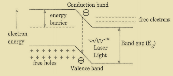
Figure 14: Energy Level diagram of Semiconductor Laser
The photons moving at the plane of the junction travels back and forth by reflection between two sides placed parallel and opposite to each other and grow in strength.
After gaining enough strength, it gives out the laser beam of wavelength 8400Å. The nature of output is continuous wave or pulsed output. The power output from this laser is 1mW. The wavelength of laser light is given by
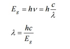
Where Eg is the band gap energy in joule.
ADVANTAGES
- It is very small in dimension.
- The arrangement is simple and compact.
- It exhibits high efficiency.
- It is operated with lesser power than ruby and CO2 laser.
- The laser output can be easily increased by controlling the junction current
- It requires very little auxiliary equipment
- It can have a continuous wave output or pulsed output.
DISADVANTAGES
- It is difficult to control the mode pattern and mode structure of laser.
- The output is usually from 5 degree to 15 degree i.e., laser beam has large divergence.
- The purity and monochromacy are power than other types of laser
- Threshold current density is very large (400A/mm2).
- It has poor coherence and poor stability.
APPLICATION
- It is widely used in fibre optic communication
- It is used to heal the wounds by infrared radiation
- It is also used as a pain killer
- It is used in laser printers and CD writing and reading.
Key Takeaways
- It is a solid-state semiconductor laser. It is a specifically fabricated p-n junction diode.
- Semiconductor laser is based on the principle that when a p-n junction diode is forward biased, the electrons from the n – region and the holes from the p- region cross the junction and recombine with each other.
- During the recombination process, the light radiation (photons) is released from a certain specified direct bandgap semiconductor like Ga-As. This light radiation is known as recombination radiation.
- The photon emitted during recombination stimulates other electrons and holes to recombine. As a result, stimulated emission takes place which produces laser.
- A semiconductor laser is a device that causes laser oscillation by flowing an electric current to the semiconductor.
- Semiconductor lasers require, for the active medium, a direct gap material, and accordingly, the normal elemental semiconductors like Si or Ge cannot be used.
A film of thickness from 0.5 to 10 μm is a transparent medium of glass, mica, air enclosed between glass, soap film, etc. When the light is made incident on this thin film partial reflection and partial refraction occur from the top surface of the film. The refracted beam travels in the medium and again suffers partial reflection and partial refraction at the bottom surface of the film. In this way several reflected and refracted rays are produces by a single incident ray. As they moves are superimposed on each other and produces interference pattern.
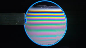
INTERFERENCE IN UNIFORM THIN FILM
Consider a thin film of uniform thickness ‘t’ and refractive index μ bounded between air. Let us consider monochromatic ray AB is made incident on the film, at B part of ray is reflected (R1) and a part is refracted along BC. At C The beam BC again suffer partial reflection and partial refraction; the reflected beam CD moves again suffer partial reflection and partial refraction at D. The refracted beam R2 moves in air. These two reflected rays R1 and R2 interfere to produce interference pattern.
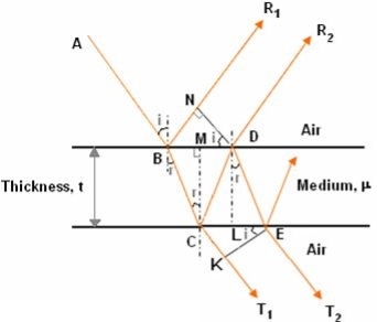
The optical path difference between the two reflected rays
= (BC + CD) - BN
In ΔBDN, sin i = BN / BD and BC = CD as ΔBMC ≡ ΔMCD, therefore
= 2BC – BD sin i
In ΔBMC, cos r = t /BC, therefore


In ΔBMC, tan r = BM / t, therefore

According to snell’s law


 ................ (1)
Correction on account of phase change at reflection:
When a beam is reflected from a denser medium (ray R1 at B), a path change of λ/2 occur for the ray.
 ….............. (2)
Therefore the true path difference is
Condition of Maxima (Bright Fringe)
Maxima occur when path difference


 ............... (3)
Condition for Minima (Dark Fringe)
Minima occur when path difference


 ................. (4)
INTERFERENCE IN THIN FILM (TRANSMITTED RAYS)
The optical path difference between transmitted rays T1 and T2 will be
This path difference is calculated in the same way as above to get
= 2tcosr ................. (5)
Condition of Maxima (Bright Fringe)
Maxima occur when path difference,

 ................... (6)
Condition for Minima (Dark Fringe)
Minima occur when path difference,

 ............. (7)
1. A thin film of soap solution is illuminated by white light at an angle of incidence i = sin-1(4/5). In the reflected light, two dark consecutive overlapping fringes are observed corresponding to wavelengths 6.1 x 10⁻⁷ m and 6.0 x 10⁻⁷ m. The refractive index for soap solution is 4/3. Calculate the thickness of the film.
Given, µ = 4/3, λ1 = 6.1 x 10⁻⁷ m λ2 = 6.0 x 10⁻⁷ m
Solution:
Sin i = 4/5
µ = Sin i / Sin r
Sin r = sin i / µ = ⅘ / 4/3
= sin r = ⅗ = 0.6
Cos r = √1 – sin2r = 0.8
Given two consecutive fringes are overlapping,
nλ1 = (n + 1)λ2
= nλ1 – nλ2 = λ2
= n = λ2 / λ1 – λ2 = 6.0 x 10⁻⁷ / 6.1 x 10⁻⁷ – 6.0 x 10-7
= 60
Now, 2μt Cos r = nλ1
t = nλ1 / 2μ Cos r = 60 x 6.1 x 10-7 / 2 x (4/3) x 0.8
t = 1.72 x 10⁻⁵ m = 1.72 x 10⁻² mm
2. A soap film of refractive index 1.33 is illuminated by the light of wavelength at an angle of 45 degrees. There is complete destructive interference. For, find the thickness of the film.
Given
Refractive index = 1.33, i = 45°,
Solution:
µ = Sin i / Sin r
Sin r = sin i / µ = Sin 45 / 1.33 = (1 /√2) / 1.33
= 1/(√2) (1.33)
Sin r = 0.5317
Cos r = √1 – sin2r = 0.8496
For destructive interference
2μt Cos r = nλ
2 x 1.33 x t x 0.8469 = 1 x 5890 x 10-10 Å
t = 5890 x 10-10 / 2 x 1.33 x t x 0.8469
= 2.61410-4 mm
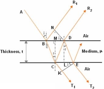
The optical path difference between the two reflected rays
= (BC + CD) - BN
In ΔBDN, sin i = BN / BD and BC = CD as ΔBMC ≡ ΔMCD, therefore
= 2BC - BNsini
In ΔBMC, cos r = t /BC, therefore


In ΔBMC, tan r = BM / t, therefore

According to snell’s law


 ................ (1)
Correction on account of phase change at reflection:
When a beam is reflected from a denser medium (ray R1 at B), a path change of λ/2 occur for the ray.
 ….............. (2)
Therefore the true path difference is
Condition of Maxima (Bright Fringe)
Maxima occur when path difference


 ............... (3)
Condition for Minima (Dark Fringe)
Minima occur when path difference


 ................. (4)
INTERFERENCE IN THIN FILM (TRANSMITTED RAYS)
The optical path difference between transmitted rays T1 and T2 will be
This path difference is calculated in the same way as above to get
 ................. (5)
Condition of Maxima (Bright Fringe)
Maxima occur when path difference,

 ................... (6)
Condition for Minima (Dark Fringe)
Minima occur when path difference,

 ............. (7)
INTERFERENCE IN WEDGE SHAPED FILM (REFLECTED RAYS)
The wedge shaped film has a thin film of varying thickness, having thickness zero at one end and increases at the other. The angle of wedge is θ. Wedge shaped film is one whose surface are inclined at an angle θ of refractive index μ bounded by non-uniform thickness.
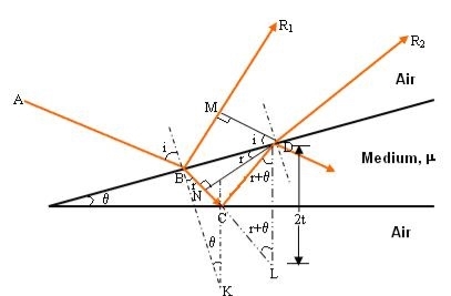
The optical path difference between the two reflected rays R1 and R2 will be
= (BC + CD) - BM
From the geometry
= (BN + NC + CD) - BM
As in ΔBMD;

And in ΔBND

According Snell’s Law,

Or
BM = BN
Thus


As in ΔNDL


As in ΔNDL


Correction on account of phase change at reflection:
When a beam is reflected from a denser medium (ray R1 at B), a path change of  /2 occur for the ray.
Therefore the true path difference is

Condition of Maxima (Bright Fringe)
Maxima occur when path difference,


Condition for Minima (Dark Fringe)
Minima occur when path difference


Newton’s Rings are the circular interference pattern first discovered by physicist Sir Isaac Newton in 1704. It is consists of concentric bright and dark rings with the point of contact of lens and the glass plate as centre,
The fringes obtained by interference of light waves by using the following arrangement
When a Plano convex lens with large radius of curvature is placed on a plane glass plate such that its curved surface faces the glass plate, a wedge air film (of gradually increasing thickness) is formed between the lens and the glass plate. The thickness of the air film is zero at the point of contact and gradually increases away from the point of contact.
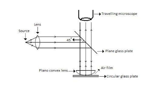
FIGURE NEWTON RING ASSEMBLY
If monochromatic (means light with single wavelength) light is allowed to fall normally on the lens from a source 'S', then two reflected rays R1 (reflected from upper surface of the film) and R2 (reflected from lower surface of the air film) interfere to produce circular interference pattern. This interference pattern has concentric alternate bright and dark rings around the point of contact. This pattern is observed through traveling microscope.
MATHEMATICAL ANALYSIS OF NEWTON’S RING
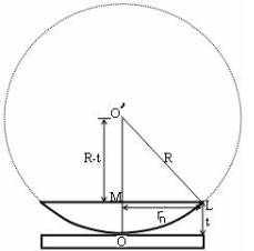
(OL)2 =(O’M)2-(ML)2 ……….(1)
R2=(R-t)2 +rn2
R2=R2 +t2-2Rt +rn2
Radius is large as compared to the thickness
So t2 is neglected as t2<< R2
R2=R2 +-2Rt +rn2
2Rt =rn2
Thickness of the film t =rn2 /2R ……….(2)
THEORY OF FRINGES:
The effective path difference between the two reflected rays R1 and R2 for a wedge-shaped film from equation
∆ = 2μtcos(r+θ) +λ/2 ……….(3)
If the light is incident normally on the lens,
r = 0 and near to point of contact θ is small;
Therefore near point of contact, (r+θ) approaches to 0 and cos(r+θ)=cos0=1
Therefore
∆ = 2μt+λ/2 ……….(4)
Also At point of contact t = 0 therefore the effective path difference ∆ = λ/2
Which is odd multiple of λ/2.
Therefore the Central fringe is dark.
BRIGHT FRINGE: CONDITION OF MAXIMA
For the condition of maxima the effective path difference
∆ = ±nλ
Using equation (4) ∆ = 2μt+λ/2 we have
2μt+λ/2= ±nλ
2μt = ± (2n-1)λ /2 ……….(5)
DIAMETER OF BRIGHT RINGS
We know by equation (2) t =rn2 /2R substitute in equation (5) we have
2μ (rn2 /2R) = ± (2n-1)λ /2
rn2 = ± (2n-1)λR /2μ
We know diameter D=2r and for nth fringe Dn=2rn
So we have Dn2=± 2(2n-1)λR /μ
Dn=
The medium enclosed between the lens and glass plate is if air therefore, =1. The diameter of nth order bright fringe will be
D=  n=0,1,2,3,4……. ……….(6)
The diameter of bright ring is proportional to square root of odd natural numbers
DARK FRINGE: CONDITION FOR MINIMA
For the condition of minima, The effective path difference
∆ =± (2n+1)λ /2
2μt+λ/2 =± (2n+1)λ /2
2μt= ±nλ ……….(7)
It is clear that for particular dark or bright fringe t should be constant.
Every fringe is the locus of points having equal thickness. Hence the fringes are circular in shape.
DIAMETER OF DARK RINGS
We know by equation (2) t =rn2 /2R substitute in equation (7) we have
2μ (rn2 /2R ) = nλ
rn2 = nλR/ μ
We know diameter D=2r and for nth fringe Dn=2rn
So we have Dn2= 4nλR/ μ
Dn= 
The medium enclosed between the lens and glass plate is if air therefore, =1. The diameter of nth order bright fringe will be
Dn=  n=0,1,2,3,4……. ……….(8)
The diameter of dark ring is proportional to square root of natural numbers.
SPACING BETWEEN FRINGES
The Newton’s rings are not equally spaced because the diameter of ring does not increase in the same proportion as the order of ring and rings get closer and closer as ‘n’ increases.
For example the diameter of dark ring is given by Dn=  where n=0,1,2,3,4…….


From above result we conclude that the fringe width reduces with increase in n.
APPLICATION OF NEWTON’S RING
1. Determination of Wavelength of Light
The diameter of the nth order ring is calculated by subtracting the left and right side position of the microscope. As we know that the square of diameter of nth dark ring is

Therefore the square of diameter of (n+p)th ring is

Subtracting both the above equation
 ………...(9)
Therefore
 .............(10)
2. Determination of Refractive Index of liquid
In order to determine the refractive index of liquid the Newton’s ring experiment is first performed for the air medium and the difference in the square of the diameter of (n+p)th and nth dark ring is found as discussed above.
 ………….(11)
After these few drops of liquid of μ refractive index is placed on the glass plate. The plano-convex lens is then placed on the glass plate, as a result a film of liquid is formed between the lens and the plate.
The difference in the square of the diameter of (n+p)th and nth dark ring is again calculated in the same manner for the liquid medium.
 …..….(12)
Dividing equation 2.29 by 2.30, we get
 …….….(13)
3. Newton’s ring with white light
If the monochromatic source is replaced by the white light, dark and bright fringes are not produced. Because the diameter of the rings depends upon wavelength and it is proportional to the square root of wavelength.
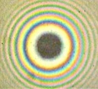
If If the monochromatic source is replaced by the white light superposition of rings take place due to different wavelength. Few coloured rings are seen around dark centre later illumination is seen in the field of view. As shown in below figure.
Example: In a Newton’s rings experiment the diameter of the 15th ring was found to be 0.59 cm and that of the 5th ring is 0.336 cm. If the radius of curvature of the lens is 100 cm, find the wave length of the light.
Solution:
The given data are
Diameter of Newton’s 15th ring (D15) = 0.59 cm = 0.59×10⁻² m
Diameter of Newton’s 5th ring (D5) = 0.336 cm = 0.336 × 10⁻² m
Radius of curvature of lens (R) = 100 cm = 1 m
Wave length of light (λ) = ?
Here m is difference between rings = 15-5=10
λ = D2n+m - D2n / 4mR
λ = (0.59×10⁻² )2- (0.336 × 10⁻²)2 / 4 x 10 x 1
λ = 0.3481 x10⁻⁴ – 0.112896 x10⁻⁴ / 40
λ =0.00588 x 10⁻⁴ m
λ =5880 x 10-10 m
λ =5880Å
Anti-reflective coatings are used in a wide variety of applications where light passes through an optical surface, and low loss or low reflection is desired. Examples include anti-glare coatings on corrective lenses and camera lens elements, and antireflective coatings on solar cells.
Thin film anti-reflection coatings greatly reduce the light loss in multi-element lenses by making use of phase changes and the dependence of the reflectivity on index of refraction. A single quarter-wavelength coating of optimum index can eliminate reflection at one wavelength. Multi-layer coatings can reduce the loss over the visible spectrum.
The idea behind anti-reflection coatings is that the creation of a double interface by means of a thin film gives you two reflected waves. If these waves are out of phase, they partially or totally cancel. If the coating is a quarter wavelength thickness and the coating has an index of refraction less that the glass it is coating, then the two reflections are 180 degrees out of phase.
A single MgF2 (n = 1.38) quarter-wave coating on glass (n = 1.5) substrate reduces its reflectance at normal incidence from 4 to nearly 1.2%. This reduction in reflectance takes place at one particular wavelength. The reflectance increases on either side of this wavelength. To improve the performance of multi-layer AR coatings, we have more variables at our disposal in the forms of the thickness and index of refraction of each of the layers.
Computer simulations can be carried out to select optimum combinations of thin film coatings to achieve low reflectance over the desired spectral range. Two quarter-wave coatings with materials of high and low indices of refraction can give zero reflectance at two-wavelengths, but reduction in reflectance in the spectral range between the two-wavelengths is rather small. A three-layer coating is more effective in reducing reflectance over a broad spectral range.
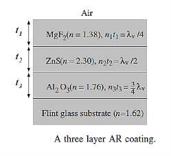
Figure 15: Three Layer AR coating
Figure shows a sequence of three layers on light flint glass substrate. The reflectance of this combination over most of the visible spectrum is less than 0.03% as compared to 4% reflectance of an air–glass interface and 1.2% reflectance of a MgF2 coated glass substrate. The AR coatings usually have no more than three or four layers and show only marginal degradation in performance for deviations from normal incidence.
Determination of thickness of very thin wire or foil:
DIAMETER OF A THIN WIRE:
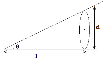
Take two optically flat glass plates and held them together at one end so that a wedge-shaped air film is formed with a very small wedge angle ѳ. At other end put the wire or foil whose diameter is to be determined. From the figure, tan ѳ = d/l……………………. (1)
Also, tan ѳ =λ/2μꞵ……………. (2)
From 1 &2
d/l = λ / 2μꞵi.e. d = lλ / 2ꞵ
For an air film μ =1, which is distance between two dark or bright/dark bands can be measured experimentally. Therefore, diameter can be determined.
Determination of Wavelength of incident Light
In order to determine the wavelength of monochromatic source an experimental arrangement is set up as shown in figure.
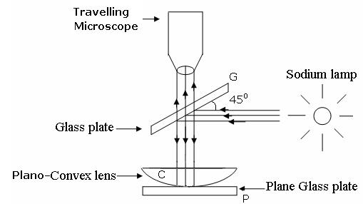
The monochromatic light is made incident on the plano-convex lens and the reflected light is viewed in travelling microscope. Microscope is adjusted till the circular rings came in focus. Now the microscope crosswire is focused on the central dark spot and is moved slowly at one side, say right side. As the cross – wire moves in the field of view, dark rings are counted. The movement is stopped when it reaches at the 22nd dark ring. The cross wire is moved in opposite side and stopped at 20th dark ring such that the vertical cross-wire is made tangential to the ring. Thus, starting from 20th, the microscope position is noted down for 18th, 16th, 14th, …...6th ring. The microscope is quickly moved to the left side of the ring pattern and the positions of microscope is again noted down for 6th, 8th, 10th,20th ring. The diameter of the nth order ring is calculated by subtracting the left and right-side position of the microscope. As we know that the square of diameter of nth dark ring is

There-fore the square of diameter of (n+p) th ring is

Subtracting both the above equation

Therefore

Determination of Refractive Index of liquid
In order to determine the refractive index of liquid the Newton’s ring experiment is first performed for the air medium and the difference in the square of the diameter of (n+p) th and nth dark ring is found as discussed above.

After this few drop of liquid of refractive index is placed on the glass plate. The plano-convex lens is then placed on the glass plate, as a result a film of liquid is formed between the lens and the plate.
The difference in the square of the diameter of (n+p)th and nth dark ring is again calculated in the same manner for the liquid medium.

Dividing equation, we get

Radius of curvature of lens:
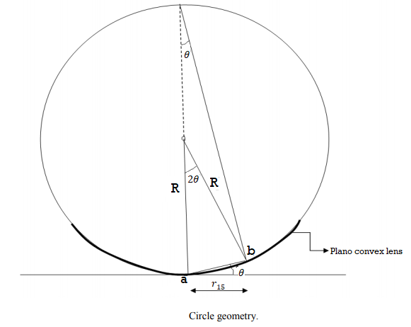
This method involves the measurement of radius of a clearly visible dark fringe preferable away from the centre. By knowing the fringe number, the thickness of the air film which creates the path difference causing the destructive interference leading to the formation of that dark fringe is calculated. Radius of curvature is obtained from the formula which is easily derived from trigonometrical relationships. It is assumed that the radius of curvature is large in comparison with the path difference.
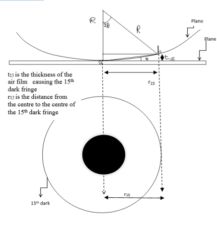
From the figure
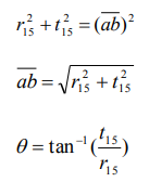
From trigonometry, assuming ab to be very small,
So

Where R is the radius of curvature of the Plano convex lens
Testing of surface flatness:
If an optical flat is placed upon another flat reflecting surface (without pressure) it will not form an intimate contact, but will lie at some angle 0 making an inclined plane. If the optical flat be now illuminated by monochromatic source of light, the eye if placed in proper position, will observe a number of bands. These are produced by the interference of the light rays reflected from the lower surface of the top flat and the top surface of the lower flat through the very thin layer of air between the flats. The angles 6 between the two flats is shown exaggerated too much. S is the source of monochromatic light. At point A, the wave of incident beam from S is partially reflected along AB and is partially transmitted across the air gap along AC. At C, again the ray is reflected along CD and passes out towards the eye along CDE. Thus, the two reflected components, reflected at A and C are collected and recombined by the eye, having travelled paths whose lengths differ by an amount ACD.
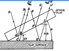
If the path lengths of the two components differ by an odd number of half wavelengths, then condition for complete interference is achieved. If the surface is perfectly flat, then condition of complete interference is satisfied in a straight line across the surface as the surface at right-angles to the plane of the paper is parallel to the optical flat. Therefore, a straight dark line will be seen passing through point C. Consider another ray incident along path SFH. Again, this ray is also spilatted into two components. It is obvious that the path difference of the two component rays will keep on increasing along the surface due to angle 9.
Thus, if the path difference FHI be 3X12 or the next odd number of half wavelengths, then interference will occur and a similar fringe will be seen. Next when path difference is 5K/2, again there will be another dark fringe. At the intermediate point between the points C and H, the path difference will be an even number of half wavelengths and the two components will be in phase producing a light band.
Thus, in case of a perfectly flat surface, we will have pattern of alternate light and dark straight lines on the surface. Any deviation from this pattern will be a
measure of the error in the flatness of the surface being inspected.
Anti-reflecting films and Highly reflecting film:
The cancellation (destructive interference) of reflected light waves is utilized to make non-reflective coatings. Such coatings are commonly found on some camera lenses or binocular lenses, and often have a bluish tint. The coating is put over glass, and the coating material generally has an index of refraction less than that of glass. In that case, then, both reflected waves have a 180° phase shift, and a film thickness of 1/4 wavelength (in the film) would produce a net shift of 1/2 wavelength, resulting in cancellation.
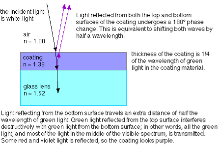
For non-reflective coatings, then, the minimum film thickness required is:

Where n is the index of refraction of the coating material.
Note that you have to be very careful to account for whether a phase shift occurs at an interface where reflection is taking place. In some cases, the minimum film thickness required for constructive interference is a quarter of the wavelength; in other cases, the minimum film thickness must be half a wavelength for constructive interference to take place. It all depends on whether or not a phase shift occurs for reflections at both interfaces, one interface, or neither interface.
References:
1. LASERS: Theory and Applications: Thyagarajan K and Ghatak A.K.
2. Nanomaterials & Nanotechnologies and Design: M.F. Ashby, Paulo Ferreira and Daniel L. Schodek, Elsevier Publications.
3. University Physics: Young and Freedman (Pearson Education).
4. Optics: Jenkins and White (Tata Mcgraw Hill)