Unit - 4
Electric Circuit Analysis using Laplace Transforms
Consider an LTI system by a complex exponential signal of the form
x(t) = Gest.
Where s = any complex number = σ+jω
σ = real of s, and
ω = imaginary of s
The response of LTI can be obtained by the convolution of input with its impulse response i.e.
y(t)=x(t)×h(t)=
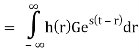
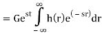
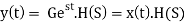
Where H(S) = Laplace transform of 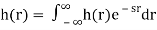
Similarly, Laplace transform of 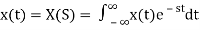
1) Step Function:
U(t)=1 t≥0
=0 t<0

Fig 1 Step Signal

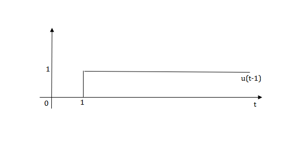
Fig 2 Shifted unit step signal
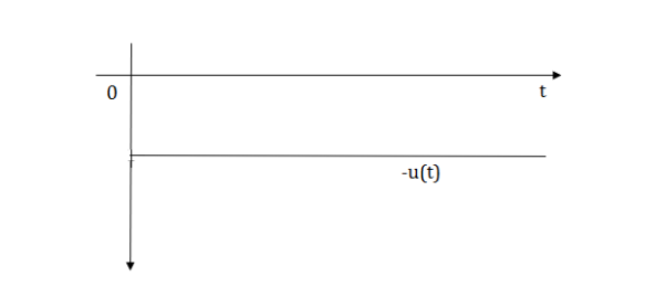
Fig 3 Unit step signal -u(t)
2) Pulse Function:
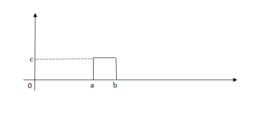
Fig 4 Pulse signal
L[u(t)]=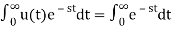 =
=
f(t)<—>F(s)
f(t-a)= F(s)
F(s)
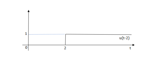
L[u(t-a)]=
Laplace transforms of pulse
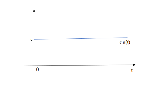
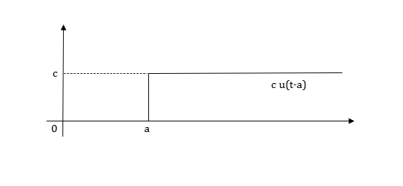
Fig 5 Shifted Pulse signal
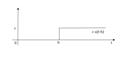
Fig 6 Shifted Pulse signal
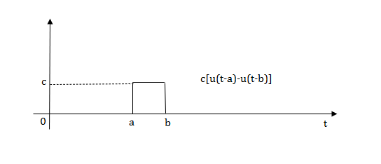
Fig 7 Final required Pulse signal
Examples
Q.1) Write equation for given waveform

Sol: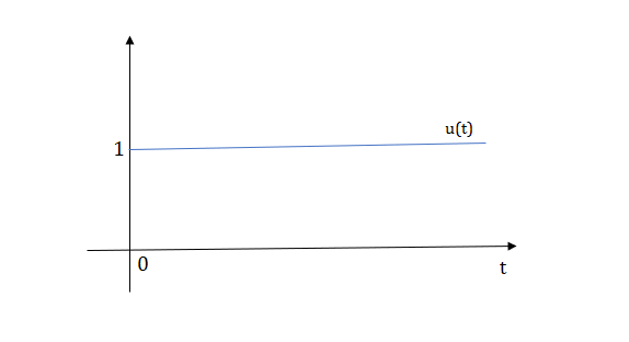
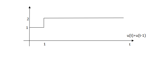


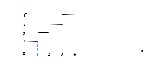
The final equation is=u(t)+u(t-1)+u(t-2)+u(t-3)-4u(t-4)
As the waveform is stopped at t=4 with amplitude 4,so we have to balance that using -4u(t-4).
Ramp function:

Fig 8 Ramp Function
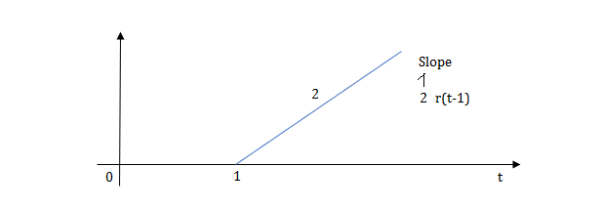
Fig 9 Shifted Ramp Function
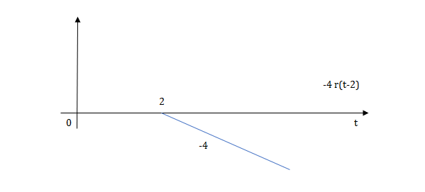
Fig 10 Shifted Ramp Function
L[r(t)] =
R(t)=tu(t)
R(t)=∫u(t)
Impulse Signal:
This signal has zero amplitude everywhere expect at the origin. Fig below shown the representation of Impulse signal.
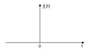
Fig 11 Impulse Function
The mathematical representations
A (t) = 0 for t ≠0
 dt = A e
Where A represent energy or area of the Laplace Transform of Impulse signal is
L [A (t) ]= A
The transfer function of a linear time invariant System is the Laplace transform of the impulse response of the system
Example
Q) Write the equation for the given waveform?
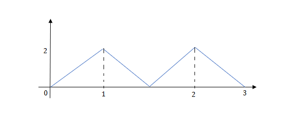
Sol: Calculating slope of above waveform
Slope for (0,0) and (1,2)
a1 slope= =2
=2
a2 slope= =-4
=-4
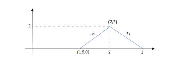
a3 slope =4 and a4= -2
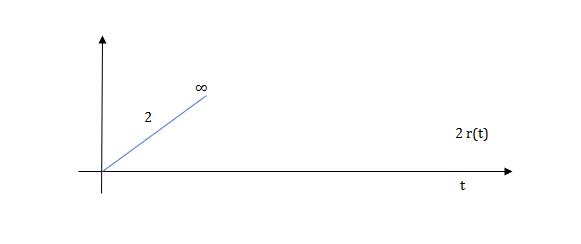
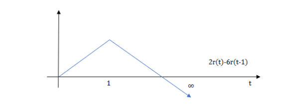
At t=1 slope changes from 2 to -4 so we need to add -6r(t-1) to 2r(t) to get the slope of -4.
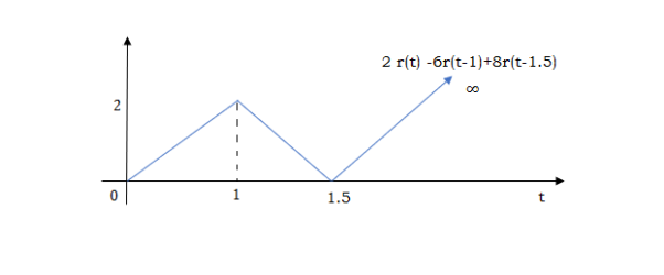
At t=1.5 slope changes from -4 to 4 so adding 8r(t-1.5) to get slope of 4
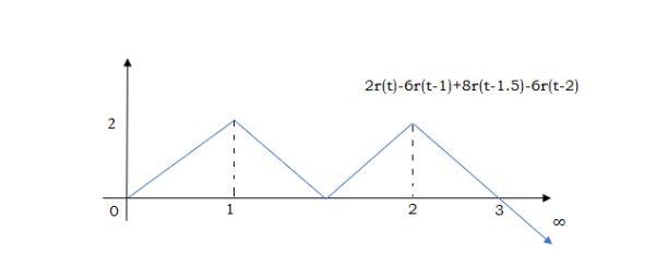
At t=2 slope changes from +4 to -2 so we add -6r(t-2). But we need to stop the waveform at t=3. Hence, we have to make slope 0. Which can be done by adding +2r(t-3). Final equation is given as 2r(t)-6r(t-1.5)+8r(t-1.5)-6r(t-2)+2r(t-3)
Analysis of electrical circuits using Laplace Transform for standard inputs
LAPALACE TRANSFORM:
If LT[f(t)]= F(s)
Where F(s)= dt
dt
f(t) F(s)
F(s)
 sF(s)-f(0-)
 f(t)
f(t) S2F(s)-sf(0-)-f’(0-)
Now, we find Laplace for 
 =
= +
+
Now if f(t)=ic(t) [current through capacitor]
 =
= +
+
 =
= +
+
=[q(0)-q( )]+
)]+
=[q(0)-0]+
Multiplying both sides by 1/C
 =
= +
+
Vc(t)= +
+
Vc(t)=Vc(0)+
By Laplace Transform
Vc(s)= +
+
Vc(s)= +
+
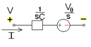
Fig 12 Laplace transformed circuit for C
Now by source conversion
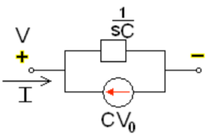
Fig 13 Source transformed circuit for C
 =
= +
+
Now if f(t)=VL(t) [voltage across inductor]
 =
= +
+
 =
= +
+
= -
- ]+
]+
= -0]+
-0]+
Multiplying both sides by 1/L
 =
= +
+
iL(t)=iL(0)+
By Laplace Transform
IL(s)= +
+
IL(s)= +
+
NOTE: Voltage------->Series circuit
Current------->Parallel circuit

Fig 14 Laplace transformed circuit for L
By source transformation

Fig 15 Source transformed circuit for L
Current through capacitor
iC(t)=
IC(s)=C[sVc(s)-Vc(0)]
Vc(s)= +
+
Voltage about inductor,
VL(t)=
VL(s)=L[sIL(s)-iL(0)]
IL(s)= +
+
Examples
Que For given RL circuit find the differential equation for current i?

Fig 16 Series RL circuit
After switch is closed applying KVL
 =0
=0
This is first order homogeneous differential equation so
 dt
dt
Integrating both sides
Ln i=  t+K
t+K
Taking antilog of both sides
i=k
At t=0
i(0)= =I0
=I0
 =ke0
=ke0
The particular solution is given as
i=  for t≥0
= for t<0
Ques: Find IL(0) for the given circuit below
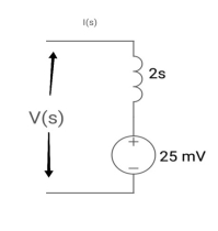
Sol: From above circuit
L = 2H
LiL (0) = 25 mv
IL (0) = 12.5 m A
Que: Find value across capacitor?
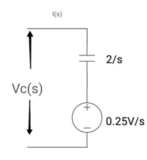
Sol: From above circuit we can write
1/cs = 2/s
C=1/2f
Vc (0)/s = 0.25v/s
Vc(0)= .25v
Ques: Find voltage across capacitor?
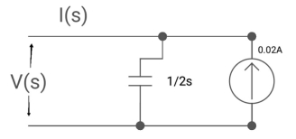
Sol: 1/cs = 1/2S
C=2F
CVc (0) = 0.02
Vc(0)= 0.01V
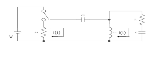
Que:
(a) switch is at before moving to position = at t= 0, at t= 0+, i1(t) is
(a) –V/2R (b) –V/R (c) – V/4R
Sol:
I1(t) L.T I1(s)
I2(t) L.T I2(s)
Then express in form
[ I1(s)/I2(s)] [::] = [:]
Drawing the ckl at t = 0-

:. The capacitor is connected for long
Vc1(0-)= V
iL(0-) =0
Vc2(0-)=0
At t= 0+


i1 (0+) = -V/2R
For t>0 the circuit is

Apply KVL
-R i1(t) -1/c  dt -L
dt -L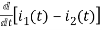 =0
=0
Also, we can deduce i1(t)- i2 (t) = iL(t)
-Ri1(t) -1/c  - L
- L = 0
= 0
-RI1(s)-[ -
- ]-L[sI1(s)-iL(0-)]=0
- RI1(s)- -
-  -s L I2(s)=0
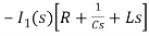 - s L I2(s)= -
  (1)
(1)
Again
-Ri2(t) ) -1/c  dt -L
dt -L =0
=0
-Ri1(t) -1/c  - L
- L = 0
= 0
Taking Laplace Transform
-RI2(s)- [ -
- ]- L[s IL(s)- iL(0-)]=0
-RI2(s)-  -Ls[ I1(s)- I2(s)]=0
 - s L I1(s)=0 (2)
Hence in matrix representation
 =
= 
Ques: All initial conditions are zero i(t) L.T, I(s), then find I(s)?
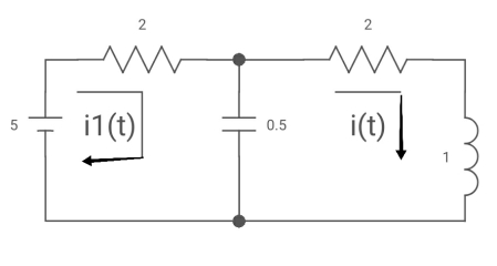
Sol: Drawing Laplace circuit
(2+S) 11 2/S
Zeq = [(2+S)2/S]/[2+S+2/S]=[2(S+2)]/[S2+2s+2]
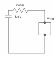
V1(s) = [5/S{2(S+2)/S2+2S+2}]/[2+{2(S+2)/ S2+2S+2}]
V1(s) = [5(S+2)/S]/[S2+ 3S +4]
I(s) = V1(s)/(S+2) =(5/S)/(S2+35+4)
Initial and Final Value Theorem
The initial value theorem
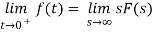
This theorem is valid if and only if f(t) has no impulse functions.
The final value theorem
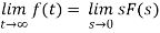
This theorem is valid if and only if all but one of the poles of F(s) are in the left-half of the complex plane, and the one that is not can only be at the origin.
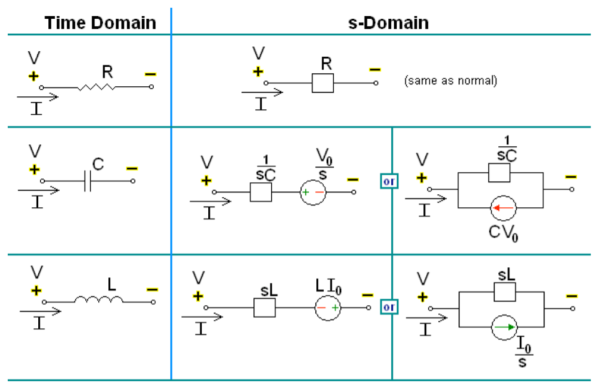
Steps for Laplace transform circuit analysis:
1. Redraw the circuit (nothing about the Laplace transform changes the types of elements or their interconnections).
2. Any voltages or currents with values given are Laplace transformed using the functional and operational tables.
3. Any voltages or currents represented symbolically, using i(t) and v(t), are replaced with the symbols I(s) and V(s).
4. All component values are replaced with the corresponding complex impedance, Z(s).
5. Use DC circuit analysis techniques to write the s-domain equations and solve them. Check your solutions with IVT and FVT.
6. Inverse-Laplace transform s-domain solutions to get time domain solutions. Check your solutions at t = 0 and t = .
Transformed network with initial conditions
Solved Examples
Que: The switch is at before moving to position = at t= 0, at t= 0+, i1(t) is
(b) –V/2R (b) –V/R (c) – V/4R (d) 0

Sol:
I1(t) L.T I1(s)
I2(t) L.T I2(s)
Then express in form
[ I1(s)/I2(s)] [::] .[:]
Drawing the ckl at t = 0-
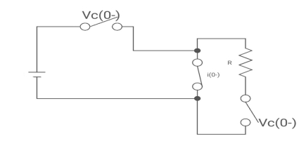
Fig 17 circuit at t=0-
:. The capacitor is connected for long
Vc1(0-)= V
iL(0-) =0
Vc2(0-)=0
At t= 0+
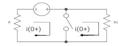
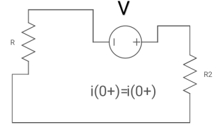
Fig 18 Circuit at t=0+
i1 (0+) = -V/2R
For t>0 the circuit is
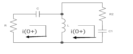
Fig 19 KVL in Circuit
Apply KVL
-R i1(t) -1/c  dt -L
dt -L =0
=0
Also, we can deduce i1(t)- i2 (t) = iL(t)
-Ri1(t) -1/c  - L
- L = 0
= 0
-RI1(s)-[ -
- ]-L[sI1(s)-iL(0-)]=0
- RI1(s)- -
-  -s L I2(s)=0
 - s L I2(s)= -
  (1)
(1)
Again
-Ri2(t) ) -1/c  dt -L
dt -L =0
=0
-Ri1(t) -1/c  - L
- L = 0
= 0
Taking Laplace Transform
-RI2(s)- [ -
- ]- L[s IL(s)- iL(0-)]=0
-RI2(s)-  -Ls[ I1(s)- I2(s)]=0
 - s L I1(s)=0 (2)
Hence in the matrix representation
 =
= 
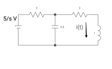
Ques: All initial conditions are zero i(t) I(s), then find I(s)?

Sol: Drawing Laplace circuit

(2+S) 11 2/S
Zeq = [(2+S)2/S]/[2+S+2/S]=[2(S+2)]/[S2+2s+2]

V1(s) = [5/S{2(S+2)/S2+2S+2}]/[2+{2(S+2)/ S2+2S+2}]
V1(s) = [5(S+2)/S]/[S2+ 3S +4]
I(s) = V1(s)/(S+2) =(5/S)/(S2+35+4)
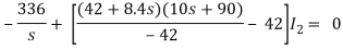
Que) There is no initial energy stored in this circuit. Find i1(t) and i2(t) for t>0?
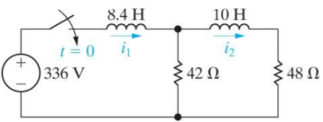
Sol:
When circuit is closed the network is shown
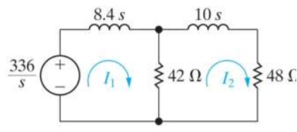
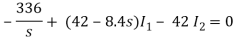
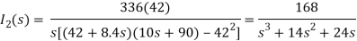
(10s+90)I2 - 42 I1 = 0
I1 = 

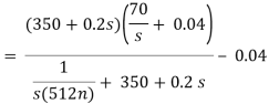
Que) Find v0 (t) for t > 0.

Sol: Taking Laplace transform of above circuit we have,
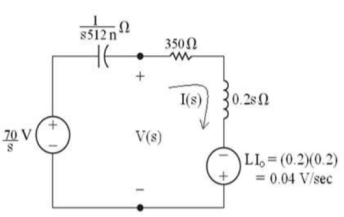
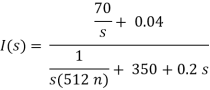
V(s) = (350 + 0.2s)I(s) - 0.04

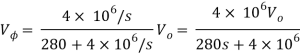
Que) There is no initial energy stored in this circuit. Find vo if ig = 5u(t) mA.

Sol: Laplace Transform of above circuit we get
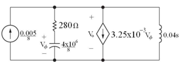

By voltage division we get

Que) Find value of current i(t) for the given circuit?

Sol:
Applying KVL we get

Taking Laplace transform of above equation we get
There is no initial current in inductor before closing the switch so i(0+)=0.
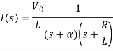
When α ≠ 
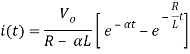
When α = 
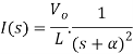
Taking ILT we get

Que) For the circuit shown below find the value of i1(t) and i2(t) and output voltage across 5 Ohm resistor when the switch is closed also find initial and final values of current?
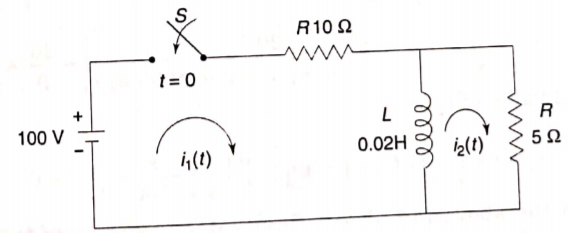
Sol: By KVL we have
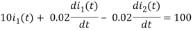
Taking LT of above equations, we get
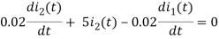
(10+0.02s)I1(s) - 0.02sI2(s) = 
(5+0.02s)I2(s) - 0.02sI1(s) = 0
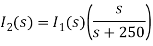
Solving above equation we get
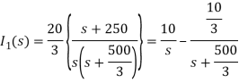

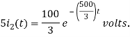
By inverse Laplace transform we get


The voltage across 5 Ohm resistor is
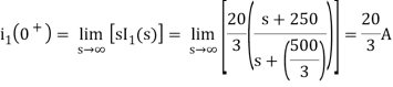
The initial value of i1(t) is
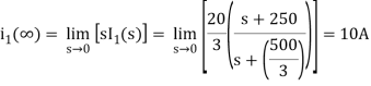
The final value of i2(t) is
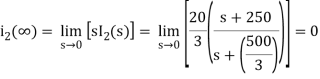
The initial value of i2(t) is

The Final value of i2(t) is
For unit step function:
u(t) = 0 t<0
1 t>0
L {u(t)} = F(s) =  -st dt = 1/s
For impulse function
∂(t) = { 0 t
1 t=0 }
L [∂(t)] = F(s) =  e-st dt = 1
Unit ramp function:
r (t) = 0 t ≤ 0
t t≥ 0
L { t u(t) } =  e-st dt = t (-1/s e -st ) | 0∞ -
  e-st dt
= 0 + 1/s  e-st dt
= 1/s (-1/s e -st ) | 0∞
= 1/ s 2
Exponential function:
f(t) = e-at u(t) where a > 0 and u(t) is the unit step function
F(s) =  dt
dt
F(s) =  at e -st dt
-e – (s+a) t / s + a | t=0t=∞ = 1/ s + a
Sinusoidal function
L { sin(wt)} =  jwt – e – jwt / 2j . e -st dt
= 1/2j [ 1/ s – jw – 1/ s + jw ] = w/ s2 + w2
Cosine function
L [ coswt] =  jwt + e – jwt / 2 . e -st dt
= ½ [ 1/s-jw – 1/ s+jw] = s/ s2 + w 2
Find the Laplace transform of x(t):

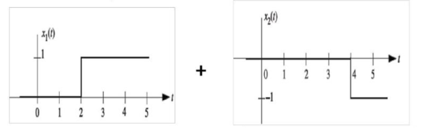
x(t) = x1 (t) + x2(t) = u(t-2) – u(t-4)
L{x(t)} = X(s) = 1/s e -2s – 1/s e -4s
X(s) = 1/s ( e-2s – e -4s)
References:
1. MahmoodNahvi, Joseph A Edminister, “Schaum’s outline of Electric Circuits”, 6th Edition, Tata McGraw-Hill, 6th Edition, 2013
2. W. H. Hayt and J. E. Kemmerly, “Engineering Circuit Analysis”, McGraw Hill Education, 2013.
3. C. K. Alexander and M. N. O. Sadiku, “Electric Circuits”, McGraw Hill Education, 2004.
4. K. V. V. Murthy and M. S. Kamath, “Basic Circuit Analysis”, Jaico Publishers, 1999.
5. K. Sureshkumar, “Electric Circuits & Network”, Pearson Publication
6. Del Toro, “Electrical circuit”, Prentice Hall


