Unit - 1
Single Phase Transformer
A transformer is a stationary device which works on the principle of Mutual Induction. It is used to transform electric power from one circuit to another having same frequency. It can lower or higher the value of voltage in any circuit but in correspondence to change in current.
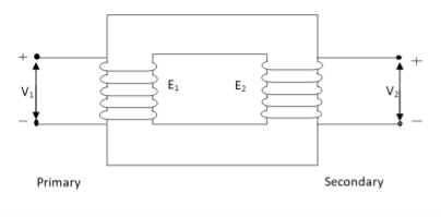
Fig. Ideal Transformer
An ideal transformer has no losses i.e. its winding have no magnetic leakage and no ohmic resistance. Hence, an ideal transformer has only two purely inductive coils wound on a loss-free core.
For above transformer when secondary is open and primary is having input sinusoidal voltage V1. An alternating, current flows due to difference in potential. As primary coil is purely inductive so, Iµ current is drawn through it. This current is very small and logs V1 by 900.
The current Iµ produces magnetic flux φ and hence are in same phase. The flux is linked with both the windings and hence, self-induced emf is produced E1 which is equal and opposite of V1. Similarly, E2 is induced in secondary which is mutually induced emf E2 is proportional to rate of change of flux and number of secondary windings.
The phasor is shown below.
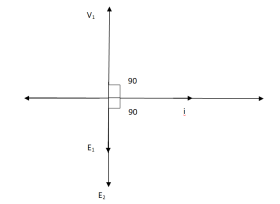
Fig. Phasor for Ideal Transformer
I Ø transformers and electrostatics
Types of transformers
Acc to input supply: I phase and δ phase
Acc to construction: core and shell type
Acc to 0/P step up and step down
Laminated steel core
Material used for core is (silicon steel) it is used for its (high permeability) and (low magnetic reluctance) magnetic field produced is very strong
The core is formed of (stacks of laminated thin steel sheets) which are electrically isolated from each other. They are typically (0.35 to 0.5 mm thick)
We can used 2 ‘L’ shaped sheets or 2 I shaped sheets for laminations
Construction and types
There 2 types of winding
- Concentric or cylindrical
- Sandwiched type
1. Cylindrical
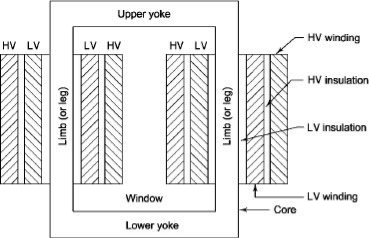
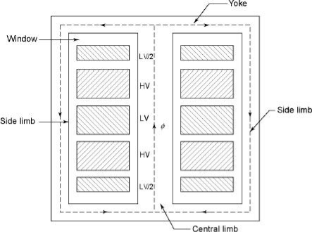
L.V. = low voltage H.V. = high voltage are mounted on same limb to minimum leakage.
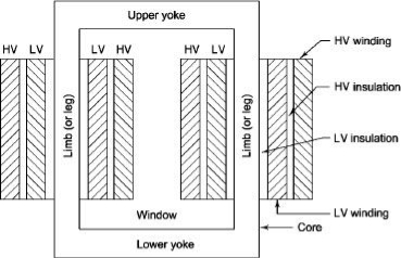
L.V. Winding placed inside and H.V. Winding placed outside with (proper insulation between the winding as it is easy to insulated L.V. Winding) than H.V. Winding.
2. Sandwiched
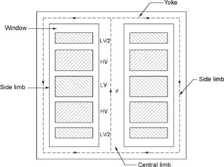
The H.V. And L.V. Winding are divided into no. Of small coils and there small windings are interleaved.
(the top and bottom winding are L.V. Coils because they are close to core)
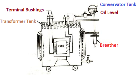
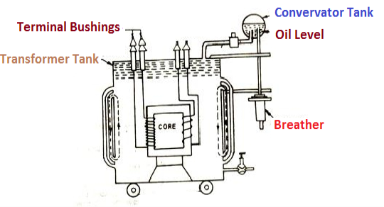
- Transformer tank: wholes assembly of winding and core placed inside the Transformer tank (sheet metal tank) which is filled with Transformer oil or insulating oil which acts as an (insulator or coolant) MCQ
- Transformer oil: (The function of oil is to remove efficiently the heat generated in core and in winding)
- Moisture should not be allowed which creeps the insulation which achieved by closed Transformer tank.
(To increase cooling surface are tubes or fins are provided)
- Conservator tank: above tank T/F tank there is one small tank in which same empty space is always provided above the oil level. (this space is required for oil to expand or contract due to temperature change) MCQ
However during contraction outside air can have moisture which will deteriorate the insulating properly of oil.
- Breather: the air goes in or out through the breather (To reduce the moisture content of their air. Same drying agents such as (silica gel or) calcium chloride) is used in the breather (The dust particles present in air are also removed by breather)
- Buccholz Relay: (for incipient (slowly increasing) faults
There is pipe connecting rain tank and conservator. On the pipe a protective device called Buccholz Relay is mounted.
When the Transformer is about to be faulty and draw range current the oil becomes very hot and decompose.
During this process different types of gases are liberated.(The Bucchoz Relay get operated by these gases) and gives an alarm to the operator. ɡȴ the fault continues to persist then there lay will trip off main circuit breaker to protect the Transformer.
Explosion Vent:
An explosion Vent or relief value is the bent up pipe filled on the main tank.
(The explosion vent consist of aluminium of oil) when the T/F becomes faulty the cooling oil get decomposed and various types of gases are liberated
(ɡȴ the gas pressure exodus certain level then the aluminium of oil (diagram) in explosion vent will burst) to release pressure. The will save main tank from getting damaged.
Transformer on No Load
When an actual transformer is put on load, we get losses (iron loss) in core and (copper loss) in primary and secondary windings. In NO LOAD (primary current is not purely reactive) the input current has to supply iron loss to core and small amount of copper loss in primary.
The no-load power is W0 = V1 I0 cos Φ0
I0 – no load primary input current
Cos Φ0 – power factor at no-load condition
I0 lags V1 by Φ0< 900
The phasor is shown below.
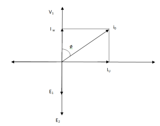
Fig: Phasor for No-Load Transformer
From above figure we can conclude that I0 has two components Iw(in phase with V1) Iµ in quadrature with V1
Iw = I0ws φ0 (iron loss component)
Iµ = I0 cos φ0 (magnetising component)
I0 = I2µ + I2w
Key takeaway
The no-load primary current I0 is very small as compared to full-load primary current. And hence, no-load cu loss is very small. So, primary input is practically equal to iron loss of transformer.
Q1>. A 2500/200 V transformer draws a no-load primary current of 0.5 A and absorbs 400 W. Find magnetising and loss currents.
Sol: Iron-loss current = No load input(W) / Primary voltage
= 400/2500 = 0.16 A
I20 = I2w + I2µ
Iµ = √I20 – I2w
= √ (0.5)2 – (0.16)2
Iµ = 0.473 A
Q2>. A 1-φ transformer has 1000 turns on primary and 200 on secondary. The no load current is 4 amp at p.f of 0.2 lagging. Find primary current and pf when secondary current is 280 A at pf of 0.6 lagging.
Sol: cos-1 0.6 = 53.130 (sin φ = 0.8)
I2 = 280/-53.130A
Φ = cos-1 0.2 = 78.50
Sin φ = 0.98
I1 = I0 + I’2
I’2 = (I2/K) ( -53.130
K = N1/N2 = 1000/200 = 5
I’2 = 280/5 (-53.130
I’2 = 56(-53.130
I1 = I0 + I’2
= 4(0.20 – j0.98) + 56(0.6 – j0.8)
= 0.80 – j3.92 + 33.6 – j44.8
I1 = 34.4 – j48.72
I1 = 59.64 ( -54.770
I lags supply voltage by 54.770
Transformer On Load
When secondary winding is loaded then the current in it is setup(IQ). The current I2 is in phase with V2 if load is non-inductive it lags if load is inductive & leads if load is capacitive.
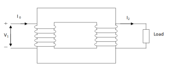
Fig: Transformer with Secondary connected to Load
An mmf is set up at secondary and hence φ2 flux is induced which is in opposition to main flux φ due to I0. The flux φ2 weaken φ and hence primary back emf E1 is reduced. An additional primary current I’2 is introduced exactly at instance when I2 is introduced. So, that magnetic effect of I2 is neutralized by I’2.
Φ2 = φ’2
N2 I2 = N1 I’2
I’2 = N2/N1 x I2 = K2 I2
The phasor is shown below,
(a)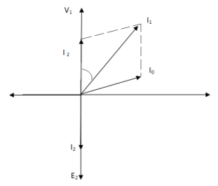
(b)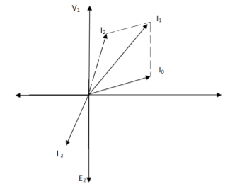
Fig. Phasor for Load Transformer
From fig (a) (non – inductive load)
I2 is in phase with E2(=V2)
I’2 is antiphase with but equal in magnitude
I1 is vector sum of I’2 and I0, but lags V1
From fig (b), Inductive load
I2 lags V2
I’2 is not in phase with I2 but equal in magnitude
I1 is vector sum of I’2& I0 but lags V1
Key takeaway
I’2/I2 = I1/I2 = N2/N1 = K
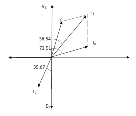
Q>. A 1- φ transformer with ratio of 440/110-V takes a no-load current of 6 A at 0.3 pf lagging. If secondary supplies 120 A at pf of 0.8 lagging. Find current taken by primary.
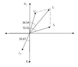
Sol>.
Cos φ2 = 0.8
Φ2 = 36.540
Cos φ0 = 0.3
Φ0 = 72.540
K = V2/V1 = 110/440 = ¼
I’2 = KI2 = 120 x ¼ = 30 A
I0 = 6A
Angle between I0& I’2
= 72.54 – 36.54
= 35.670
From vector diagram,
I1 = √(62 + 302 + 2 x 6 x 30 cos 35.67)
I1 = 35.05 A
- Losses in a Transformer [6m]
There are 2 types of losses occurring in a transformer
A) 1. Core loss or Iron loss
B) 2. Copper loss
- Core losses:
- This loss is due to the reversal of flux
- The flux set up in the core is dependent on the i/p supply as the i/p supply is constant in magnitude the flux set up will be constant and core losses are also constant.
- Core losses are voltage dependent loss they can be subdivided in 2
1. Hysteresis loss
2. Reedy current loss
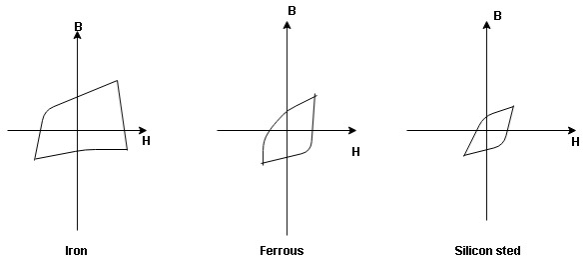
1. Hysteresis loss: The iron loss occurring in the core of T/F due to the Hysteresis curve of the magnetic material used for core is called as Hysteresis loss.
Hysteresis curve is the curve as loop which shows the properly of magnetic material to lag the flux density B behind the field Intensely H
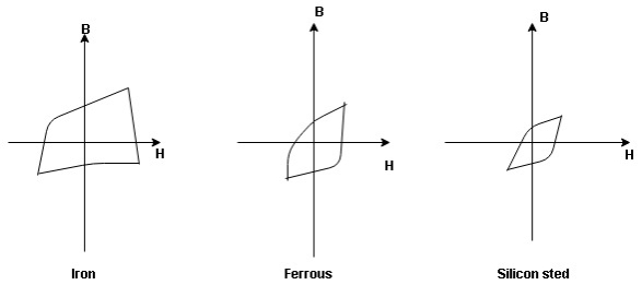
Above are the 3 different loops (Hysteresis of 3 diff. Materials)
the selection of magnetic material for the construction of core depends upon Hysteresis loop of that material having tall and narrow Hysteresis loop is selected for the T/F core
Eg: silicon Steel
Hysteresis loss depends on fold factor
PH = KH. Bm1.67 F V – watts
Where KH = constant (Hyst)
Bm = max Flux density
F = Frequency
V = Volume of core.
2. Reedy current loss:
This loss is due to the flow of reedy (circular) current in the core caused by induced emf in core
PE = Ke Bm2 f2 t2 v – watts
Where
Ke = reedy current const.
t = thickness of core
It can be reduced by using stacks of laminations instead of solid core
B] Copper loss: PCU
The Copper loss is due to resistance of the primary and secondary winding
It is load dependent / current dependent loss
As load on a transformer is variable (changing) current changes copper loss is a variable loss
Primary secondary
Total C is loss = I12R12 + I22 R22
Copper loss depends upon load on T/F and is proportional to square of load current or KVA rating of transformer
PCU I2 (KVA)2
F.L = full load
PCU (at half load) = (1/2)2 PCu F.L
= (0.5)2 PCU F.L.
Or PCu (x load) = (x) 2 PCu F.L
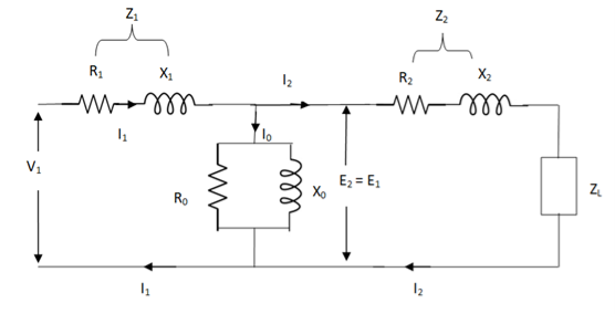
The basic transformer and its equivalent circuit both are shown below,
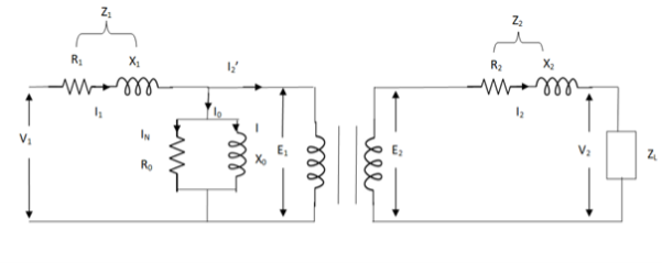
Fig. Equivalent Transformer Circuit
Iµ - magnetising component of current
Iw = working component
R0 – Non- inductive resistance
I0 – No load current
X0 = E1/I0. R0 = E1/Iw
E2/E1 = N2/N1 = K
E’2 = E2/K = E1
V’2 = V2/K
I’2 = K I2
The total equivalent circuit is again given as,
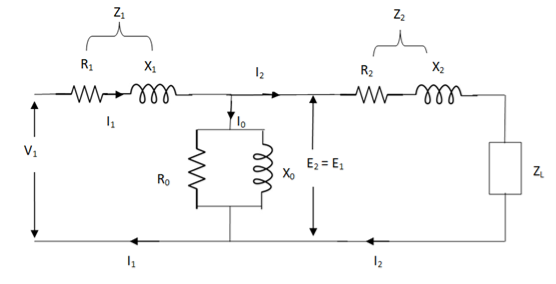
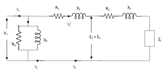
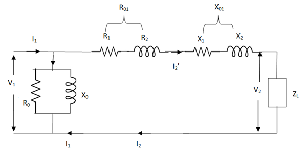
But the above circuit is exact equivalent but harder to solve so, it can be further simplified as,
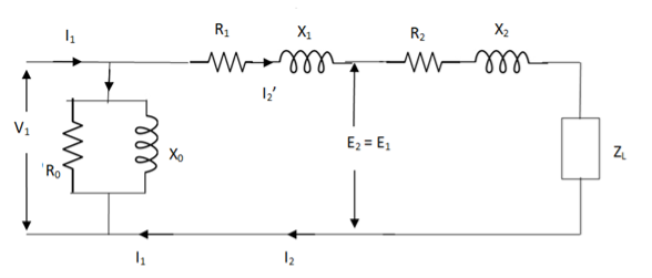
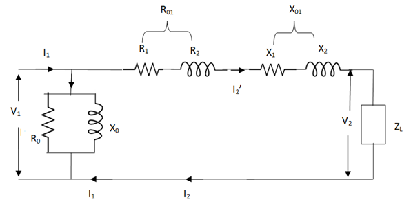
Z = Z1 + Zm || ( Z’2 + Z’L )
= Z1 + Zm(Z’2 + Z’L)/Zm + (Z’2 + Z’L)
Z’2 = R’2 + jX’2
Zm = impedance of exciting circuit
V1 = I1[ Z1 + Zm(Z’2 + Z’L) / Zm + (Z’2 + Z’L) ]
Testing-OC and SC Test
(1). Open circuit test
(2). Short circuit test
(1). OPEN CIRCUIT TEST:
Basically these tests are performed to find the basic parameters of transformers. The open circuit test is performed to determine no-load loss(core loss) and no-load current I0 which is helpful in finding X0 and R0.
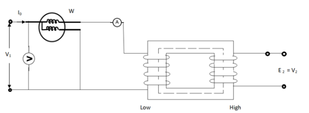
Fig. Open Circuit Test
In this test the high voltage winding is left open and the other is connected to supply.
A wattmeter W, voltmeter V and an Ammeter A are connected to L.V. Winding.
Due to applied voltage in primary, flux is set up in core, and hence normal iron loss occurs. This is recorded in Wattmeter. The current I0 is measured by Ammeter A.
Wattmeter reading represents core loss under no-load condition.
The wattmeter reading will be given as
W = V1 I0 cos φ0
Iµ = I0 Sin φ0
Iw = I0 cos φ0
X0 = V1/Iµ, R0 = V1/Iw
At no load I0 ≈ Iµ
I0 = V1 Y0
Y0 – Exciting Admittance
W = V21 G0
G0 – Exciting conductance
B0 = √ Y20 – G20
B0 – Exciting susceptance
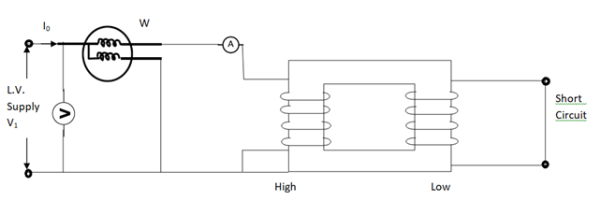
(2). SHORT CIRCUIT TEST:
This test is used to determine
(i). Equivalent Impedance (Z01, Z02), leakage reactances (X01 or X02), Total resistance (R01, R02).
(ii). Cu losses are also calculated at full load.
(iii). The regulation of transformer can be determined as Z01, Z02 can be calculated.
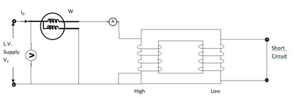
Here low voltage is short circuited. And the supply is through high voltage (primary here).
As applied voltage is small, hence the flux φ induced is also small.
As core losses are very small, the wattmeter reading is the cu-loss at full load for whole transformer.
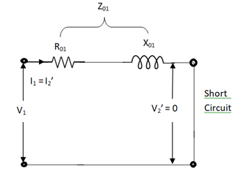
The equivalent circuit is shown below,
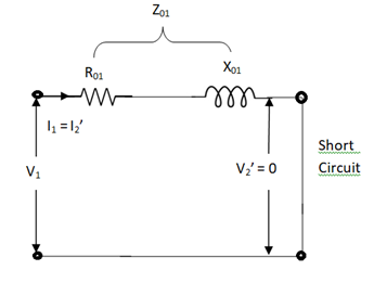
Z01 = Vsc/I1
Vsc = voltage to circulate rated load current
W = I21 R01
R01 = W / I21
X01 = √ Z201 – R201
R’2 = R01 – R1
Examples
Q1>. The primary and secondary windings of a 30 KVA, 5000/330 V, 1- φ transformer having resistance of 15 Ω and 0.02 Ω. The reactance referred to primary is 34 Ω. Calculate primary voltage required to circulate full-load current when the secondary is S.C. Also calculate the pf?
Sol. K = 330/5000 = 33/500
X01 = 34 Ω
R01 = R1 + R2/K2 = 15 + 0.02(500/33)2 = 19.59 Ω
Z01 = √ R201 – X201
= √ 19.592 + 342
Z01 = 39.23 Ω
F. L I1 = 30,000/5000 = 6A
Vsc = I1 Z01 = 6 x 39.23 = 235.4 V
S.C. Power factor = R01 / Z01 = 19.59/39.23 = 0.5
Q2). In no-load test of 1- φ transformer, the test data are
Primary voltage = 200 V,
Resistance of primary = 0.6 Ω
Secondary voltage = 100 V
Primary current = 0.6 A
Power input = 30 W
Find (a) Turns ratio (b) Magnetising component of no-load current (c) Working component (d) Iron loss
Sol>. (a). N1/N2 = 200/100 = 1
(b). W = V1 I0 cos φ0
Cos φ0 = 30/200 x 0.6 = 0.25, sin φ0 = 0.97
Iµ = I0 sin φ0 = 0.6 x 0.97 = 0.58 A
©. Iw = I0 Cos φ0 = 0.6 x 0.25 = 0.15 A
(d). Cu loss = I20 R1 = (0.6)2 x 0.6 = 0.216 W
Iron loss = 30 – 0.216 = 29.78 W
Q.3 Obtain the secondary voltage when delivered 10 KW at 0.8 PF.logging . The primary volt be 220v. The 300/600 v 50H2, 1-  Transformer has following test results.
O.C test-:200v, 0.8A 70W-L.V side
S.C test-: 12V,10A 80W-HV side
Sol: O.C TEST
W= V1I0COS θ0
70=200*0.8*Cos ∅0
Cos ∅0= 0.436
Sin ∅0=0.899
IW = I0 COS ∅0=0.8*0.436=0.35A
Iμ = I0 sin ∅0 = 0.8*0.899=0.72A
R0 =  =571.4 Ω
X0 = =
= =277.8𝛺
S.C TEST:
Z02= =
= =1.2A
=1.2A
K= =2
=2
Z01= =
= =0.3 Ω
I22R02=W
RO2= =0.7Ω
=0.7Ω
R01= =
= =0.175 Ω
X01= 
= 
X01 = 0.244 Ω
Output KVA =  =12.5
=12.5
I2=  = 20.83A
Z02=1.2A R02=0.7𝛺
X02=  =0.975𝛺
Total transformer drop refereed to secondary
= I2 (RO2COS ∅ + X02Sin ∅)
= 20.83(0.7*0.8+0.975*0.6)
= 23.85v
V2= 600 - 23.85=576.15v
Voltage Regulation:
It can be explained in terms of various parameter of transformer.
(1). When transformer has constant primary voltage.
In this case secondary voltage decreases
0V2 = No-load secondary terminal voltage
0V2 = E2 = EK1 = KV1
V2 = secondary voltage on full-load.
Voltage Regulations is change in secondary terminal voltage from no-load to full load per unit full load voltage.
% regn down = 0V2 – V2/0V2 x 100
% regn up = 0V2 – V2/V2 x 100
(2). Voltage regulation in terms of primary values.
The secondary no-load terminal voltage as referred to primary is E’2 = E2/K = E1 = V1
For secondary full load voltage referred to primary is V’2 = V2/K
% regn = V1 – V’2/V1 x 100
% regn = I1 R01 cosφ + I1 X01 sinφ / V1 x 100
(3). As the transformer is loaded, to maintain a constant output voltage, the primary voltage should be increased. Here the regulation is given as
% regn = V’1 – V1 / V1 x 100
It can also be defined as the change in primary voltage from no-load to full-load at given power factor to maintain a constant output per unit primary voltage.
Example
Q. A – 100 KVA transformer has 500 turns on primary and 80 turns on secondary. The primary and secondary resistances are 0.3 and 0.01 Ω respectively and the corresponding leakage reactances are 1.1 and 0.035 Ω. The supply voltage is 2400 V. Find
(i). Equivalent impedance referred to primary
(ii). Voltage regulation and the secondary terminal voltage for full load having pf 0.8 lagging?
Sol. Equivalent impedance referred to primary
Z01 = √R201 + X201 = R01 + jX01
R01 = R1 + R2/K2 = 0.3 + 0.01/K2 = 0.69 Ω
K = 80/500 = 4/25
X01 = X1 + X2/K2 = 1.1 + 0.035/(0.16)2 = 2.467 Ω
Z01 = 0.69 + j2.46
(ii). Secondary terminal voltage Z02 = K2 Z01
Z02 = 0.018 + j 0.063
= 0.065 ( 74.050
No-load secondary voltage = KV1
= 0.16 x 2400 = 384 V
I2 = 100 x 103/384 = 260.42 A
Full load voltage drop referred to secondary
= I2 (R02 cosφ– X02 Sinφ)
Cosφ = 0.8
Φ = 36.860
Sinφ = 0.6
= 260.42(0.018 x 0.8 – 0.063 x 0.6)
= - 6.094 V
% regn = -6.094/384 x 100
= -1.587
Secondary terminal voltage on-load
= 384 – (-6.094)
= 390.09 V
Basically, efficiency is defined as
n = output/input
But for transformer there are small amount of losses so the improved way to find efficiency is
n = output/output + losses
n = output/output + cu loss + iron loss
Or n = Input – losses/Input
= 1 – Losses/Input
For n to be maximum dn/dI1 = 0
(Ww) cu loss = I21 R01 or I22 R02
Iron loss = Hysteresis loss + Eddy current loss
= Wn + We = Wi
n = Input – losses/Input
Primary Input = V1I1 Cosφ1
n = V1 I1 Cosφ1 – losses/V1 I1 cos φ1
n = V1 I1 cos φ1 – I21 R01 – Wi / V1I1 cosφ1
= 1 – I1R01/V1cosφ1 – Wi/V1I1cosφ1
Differentiating w.r.t I1 both sides of above equation we have
Dn/dI1 = 0 – R01/V1cosφ1 + Wi/V1I21 Cosφ1
For max value dn/dI1 = 0
R01/V1cosφ1 = Wi/V1I21 cosφ1
Wi = I21 = I21 R01
Hence,
Wi = Wcu
Iron loss = copper loss
The value of output current for maximum efficiency will be
I2 = √Wi/R02
The maximum efficiency can also be given as,
nmax = full load x √ Iron loss / F.L .cu loss
Or
nmax = R’ x full load KVA x pf / R’ x full load KVA x pf + Wi + Wcu x 100
R’ = ratio of actual to full load KVA
Wi = iron loss (KW)
Wcu = copper loss (KW)
Example
Q1). In a 50 KVA, 2200/200 V, 1-φ transformer, the iron and full-load copper losses are 400 W and 450 W respectively. Calculate n at unity power factor on (i). Full load (ii). Half-full load?
Sol. (i). Total loss = 400 + 450 = 850 W
F.L output at unity power factor = 50 x 1
= 50 KVA
n = 50 / 50 + .850 = 50/50.850 = 0.98 = 98%
(ii). Half full load, unity pf
= 50 KVA/2 = 25 KVA
Cu loss = 400 x (1/2)2 = 100 W
Iron loss is same = 450 W
Total loss = 100 + 450 = 550 W
n = 25/25 + 0.55 = 25/25.55 = 0.978 = 97.8 %
Q>. A 40 KVA 440/220 V, 1- φ, 50 Hz transformer has iron loss of 300 W. The cu loss is found to be 100 W when delivering half full-load current. Determine (i) n when delivering full load current at 0.8 lagging pf (ii) the percentage of full-load when the efficiency will be max.
Sol. Full load efficiency at 0.8 pf
= 40 x 0.8/(40 x 0.8) + losses
Full load cu loss = (440/220)2 x 100
= 400 W
Iron loss = 400 + 300
= 700 W
n = 40 x 0.8/(40 x 0.8) + 0.7 = 97.8 %
(ii). KVA for maximum / F.L KVA = √ iron loss / F.L cu loss
= √300/400 = 0.866
Usually transformer efficiency is given as
n= 
But there are few transformers in which their primary winding is energized for whole day. And their secondary supplier no load. So, the core loss occurs for whole day and loss occurs only when transformer is loaded. Now n becomes.
nall – day = 
Q. Find all day efficiency of 500KVA distribution transformer whose loss and iron loss are 5.5 kW and 4.5 kW. During day it is loosed as
No of hours | Loaded in kw | Power factor |
6 | 400 | 0.8 |
10 | 300 | 0.75 |
4 | 100 | 0.8 |
4 | 0 | - |
|
|
|
Solution: Cu loss at full load of 500 KVA =5.5KW
Load at 400kw 0.8 pf =  =500KVA
Load at 300kw 0.75 pf =  =400KVA
Load loss at 400 KVA =0.8= =125KVA
Cu Loss at 400KVA =5.5 *
=3.52 KW
Cu Loss at 125KVA=5.5*( )2
)2
=0.345KW
Total Cu loss in 24 hr = (6*5.5) + (10*3.52) + (4*0.345) + 0
= 66.38kwh
Iron loss in 24hr =24*4.5 =108 kwh
Total transformer loss =66.38+108
=174.38 kwh
Transformer output 24hr= (6*400) + (10*300)
= (4*100)
=5800 kwh
nall – day = 
=  =0.97
=0.97
The polarity test of a transformer can be done by measuring only voltage at no load. The basic connections are shown in below circuit.
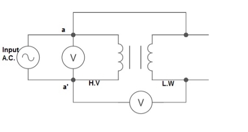
Fig: Polarity Test
From above circuit input is applied for one winding. There is another voltage ‘V’ measured between one winding from each terminal. If voltage V’ > V, polarity is additive. If voltage V’ < V, polarity is subtractive.
An auto Transformer is a special types of transformer such that a part of the winding is common to both primary as well as secondary
It has only One winding wended on a laminated magnetic core
With the help of auto Transformer the voltage can be stepped up and stepped down at any desired value
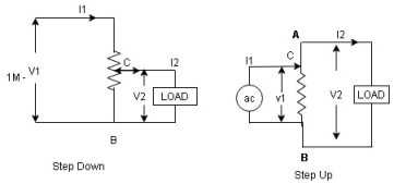
Figure. Auto Transformer
Fig A shows auto T/F as step down T/F variable terminal B C is connected to load and it acts as secondary wdg.
The position of point C is called as topping point can be selected as per requirement
Fig. B show auto T/F as step up T/F variable terminal B C is connected to supply side ie ac side and it acts as secondary winding
The operating principle of auto Transformer is same as that of 2 winding Transformer
Advantages
- Weight of copper required in an auto Transformer is always loss than that of the conventional 2 winding Transformer and hence it is chaper
- Com[act in size and loss costly.
- Losses taking place in Transformer is reduced hence efficiency is higher than conventional Transformer.
- Due to reduced resistance, voltage, regulation is better than conventional T/F.
Disadvantage:
As low voltage and high voltage sides are not separate then there is always risk of electric shocks when use for high vtg.
Applications
- Starting squirrel cage induction motor and synchronous motor.
- Auto transformer as dimmer stat
- Used as various ac to vary a. c Voltage
As the supply is in 3-phase so we need this transformer. Its alternating voltage and currents differ in phase by 120 degrees.
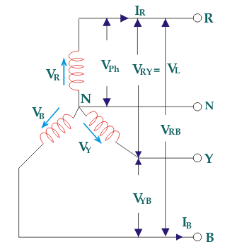
Fig: Three phase Transformer
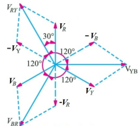
Fig: Line and phase voltage
Construction:
a) Core Type:
The construction of a core type three phase transformer is as shown in the figure. The core consists of three legs or limbs. The core is made up of thin laminated sheets to reduce eddy current losses. Each limb has primary and secondary windings in cylindrical shape (former wound) arranged concentrically. The construction is shown in the figure.
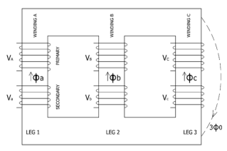
Fig: Core type 3-phase transformer
b) Shell Type:
In a shell type three phase transformer, three phases are more independent than they are in core type. Each phase has its individual magnetic circuit. The construction of shell type three phase transformer is illustrated in the figure at right. The construction is similar to that of three single phase shell type transformers kept on the top of each other.
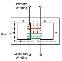
Fig: Shell Type 3-phase Transformer
Connection
Star – star or Y/Y connection: -
The below figure shows transformers connected in Y/Y on both primary and secondary sides. The ratio of line voltage and transformation ratio of line voltage and transformation ratio of both primary and secondary of each transformer in same. Hence the phase voltage VP =  . VLine (line voltage)
This connection works only if the load is balanced.
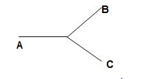
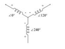
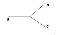
Fig: Three phase transformer Y-Y connection
- The effect of unbalanced load can be balanced by placing single load between a and n on secondary.
- Power to load is supplied by primary side A.
- As, A is in series with B and C and has b and c open on secondary, so it cannot supply required power.
- Now, B and C acts as high impedance in this condition, allowing very less flow of current in A.
- A low resistance can be connected between a and n which is approaching to short circuit. So, small current flows.
- Hence, EAN will reduce to zero but EBN and ECN will rise to full primary line voltage.
- The above shown connection is most economical for small, high-voltage transformers because the number of turns per phase and the amount of installation required is minimum.
- One more advantage is that the installation is stressed to the extent of line to neutral voltage i.e., 58% of line voltage.
- For having a sine wave voltage at output, it is necessary that sine wave of flux should be in the core. To fulfil this, we require third harmonic component of exciting current.
- To attain this if primary neutral is isolated then triple current cannot be attained. So, the best way is to provide a territory winding to each transformer of 1000 kVA rating.
Delta – Delta or Δ – Δ connection: -
- In this connection the ratio of transformation between both primary and secondary line voltage is same.
- There is no internal phase shift between phase and line voltages on either side as it was in Y-Y connection.
- The third harmonic component of current can flow in the Δ-connected transformer primaries.
- The balancing of load is easy unlike Y-Y connections.
- As the phases are 120˚ apart w.r.t. Third harmonic, the flux is sinusoidal which results in sinusoidal voltages.
- If anyone transformer becomes disabled. The system can continue to operate in open delta or V-V connection.
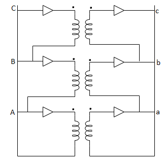
Fig: Δ-Δ connection
Wye / Delta or Y/Δ connections: -
- It is mainly used at the subtraction where the voltage is to be stopped down.
- Primary winding is Y connected and the ratio of secondary & primary line voltage is 1/
 .
. - There is 30˚Ø-shift between primary & secondary of line voltage.
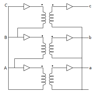
Fig: Y/Δ connection
Delta/Wye or Δ/Y connection:
- It is used where we need to stop up the voltage.
- The primary and secondary line voltages and line currents are out of phase with each other by 30˚.
- The ratio of secondary to primary voltage is
 times of the transformation ratio of each transformer.
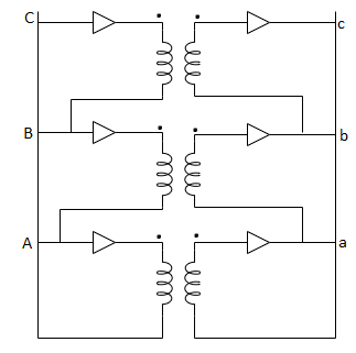
Fig: Δ-Y connection
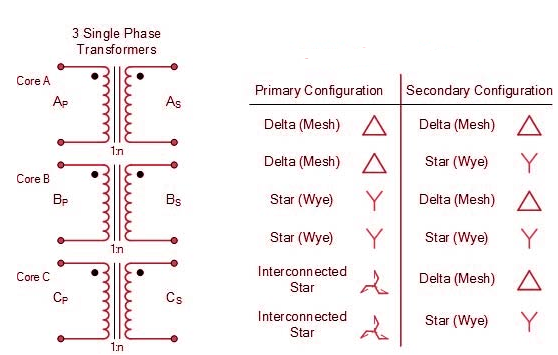
Comparative features:
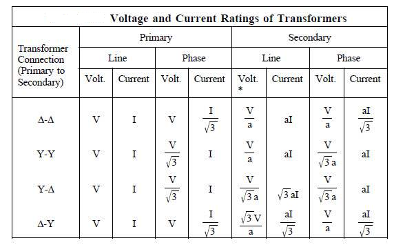
*a = N1/N2; 
Key takeaway
Que 1. A 3-Ø, 50Hz transformer has delta connected primary and star-connected secondary, the line voltage being 20,000 V and 500 V respectively. The secondary has a star connected balanced load at 0.8 lagging p.f. The line current of primary side is 5A. Determine the current in each coil of the primary and secondary line. Also find the output of the transformer?
→Phase voltage on primary side = 20,000 V
Phase voltage on secondary =  V
V
K = 
Primary phase current = 
Secondary phase current = 
= 
= 200 A
Output =  VLILcosØ
= 
= 138.56 kW
Que 2. A 100 kVA, 3Ø, 50 Hz, 3500/500 V transformer is Δ – connected on the h. V side and Y-connected on the L.V. Side. The resistance of h.V. Winding is 3.5 Ω / phase and that of L.V is 0.02 Ω per phase. Calculate the iron losses of the transformer at normal voltage and frequency if its full load efficiently be 95.1 % at 0.8 p.f.?
→Full load output = 100 × 0.8 = 80 kW
Input =  kW
kW
Total loss = Input – Output
= 83.2 – 80
= 3200 kW
K = 
K = 
= 
RO2 = R2 + k2R1
= 
= 0.044 Ωs
Full-load secondary phase current I2
= 
= 115.4 A
Total Cu Loss = 3I22RO2
= 3 × 0.044 × (115.4)2
= 1760 W
Iron Loss = Total loss – Cu Loss
= 3200 – 1760
= 1440 W
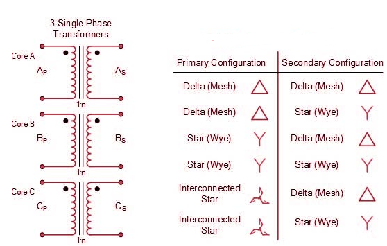
Phasor Group
- The vector for the high voltage winding is taken as the reference vector. Displacement of the vectors of other windings from the reference vector, with anticlockwise rotation, is represented by the use of clock hour figure.
- IS: 2026 (Part 1V)-1977 gives 26 sets of connections star-star, star-delta, and star zigzag, delta-delta, delta star, delta-zigzag, zigzag star, zigzag-delta. Displacement of the low voltage winding vector varies from zero to -330° in steps of -30°, depending on the method of connections.
- Hardly any power system adopts such a large variety of connections. Some of the commonly used connections with phase displacement of 0, -300, -180″ and -330° (clock-hour setting 0, 1, 6 and 11).
- Symbol for the high voltage winding comes first, followed by the symbols of windings in diminishing sequence of voltage. For example a 220/66/11 kV Transformer connected star, star and delta and vectors of 66 and 11 kV windings having phase displacement of 0° and -330° with the reference (220 kV) vector will be represented As Yy0 – Yd11.
- The digits (0, 1, 11 etc) relate to the phase displacement between the HV and LV windings using a clock face notation. The phasor representing the HV winding is taken as reference and set at 12 o’clock. Phase rotation is always anti-clockwise. (International adopted).
- Use the hour indicator as the indicating phase displacement angle. Because there are 12 hours on a clock, and a circle consists out of 360°, each hour represents 30°.Thus 1 = 30°, 2 = 60°, 3 = 90°, 6 = 180° and 12 = 0° or 360°.
- The minute hand is set on 12 o’clock and replaces the line to neutral voltage (sometimes imaginary) of the HV winding. This position is always the reference point.
Example:
- Digit 0 =0° that the LV phasor is in phase with the HV phasor
Digit 1 =30° lagging (LV lags HV with 30°) because rotation is anti-clockwise. - Digit 11 = 330° lagging or 30° leading (LV leads HV with 30°)
- Digit 5 = 150° lagging (LV lags HV with 150°)
- Digit 6 = 180° lagging (LV lags HV with 180°)
- When transformers are operated in parallel it is important that any phase shift is the same through each. Paralleling typically occurs when transformers are located at one site and connected to a common bus bar (banked) or located at different sites with the secondary terminals connected via distribution or transmission circuits consisting of cables and overhead lines.
Phase Shift (Deg) | Connection | ||
0 | Yy0 | Dd0 | Dz0 |
30 lag | Yd1 | Dy1 | Yz1 |
60 lag |
| Dd2 | Dz2 |
120 lag |
| Dd4 | Dz4 |
150 lag | Yd5 | Dy5 | Yz5 |
180 lag | Yy6 | Dd6 | Dz6 |
150 lead | Yd7 | Dy7 | Yz7 |
120 lead |
| Dd8 | Dz8 |
60 lead |
| Dd10 | Dz10 |
30 lead | Yd11 | Dy11 | Yz11 |
|
|
|
|
- The phase-bushings on a three phase transformer are marked either ABC, UVW or 123 (HV-side capital, LV-side small letters). Two winding, three phase transformers can be divided into four main categories
Group | O’clock | TC |
Group I | 0 o’clock, 0° | Delta/delta, star/star |
Group II | 6 o’clock, 180° | Delta/delta, star/star |
Group III | 1 o’clock, -30° | Star/delta, delta/star |
Group IV | 11 o’clock, +30° | Star/delta, delta/star |
Minus indicates LV lagging HV, plus indicates LV leading HV | ||
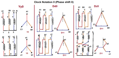
Fig. Clock Notation: 0
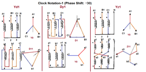
Fig. Clock Notation: 1
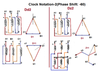
Fig. Clock Notation: 2
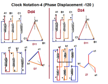
Fig. Clock Notation: 4
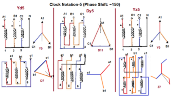
Fig. Clock Notation: 5
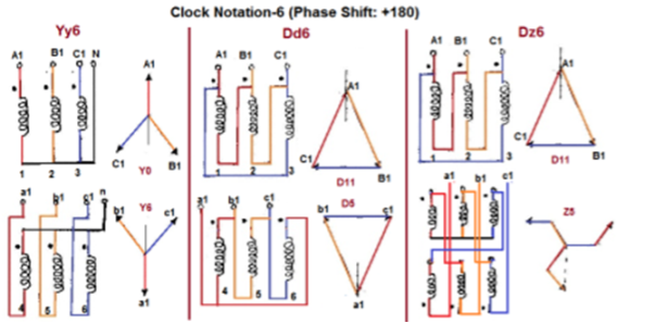
Fig. Clock Notation: 6
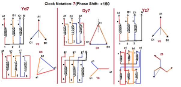
Fig. Clock Notation: 7
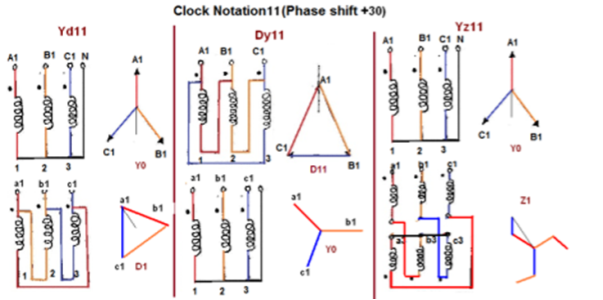
Fig. Clock Notation: 11
Key takeaway
Vector Groups are the IEC method of categorizing the primary and secondary winding configurations of 3-phase transformers. Windings can be connected as delta, star, or interconnected-star (zigzag). Winding polarity is also important, since reversing the connections across a set of windings affects the phase-shift between primary and secondary.
Examples
Que 1. A 3-Ø, 50Hz transformer has delta connected primary and star-connected secondary, the line voltage being 20,000 V and 500 V respectively. The secondary has a star connected balanced load at 0.8 lagging p.f. The line current of primary side is 5A. Determine the current in each coil of the primary and secondary line. Also find the output of the transformer?
→ Phase voltage on primary side = 20,000 V
Phase voltage on secondary =  V
V
K = 
Primary phase current = 
Secondary phase current =
= 
= 200 A
Output =  VLILcosØ
= 
= 138.56 kW
Que 2. A 100 kVA, 3Ø, 50 Hz, 3500/500 V transformer is Δ – connected on the h. V side and Y-connected on the L.V. Side. The resistance of h.V. Winding is 3.5 Ω / phase and that of L.V is 0.02 Ω per phase. Calculate the iron losses of the transformer at normal voltage and frequency if its full load efficiently be 95.1 % at 0.8 p.f.?
→ Full load output = 100 × 0.8 = 80 kW
Input =  kW
kW
Total loss = Input – Output
= 83.2 – 80
= 3200 kW
K = 
K = 
= 
RO2 = R2 + k2R1
= 0.02 + 
= 0.044 Ωs
Full-load secondary phase current I2
= 
= 115.4 A
Total Cu Loss = 3I22RO2
= 3 × 0.044 × (115.4)2
= 1760 W
Iron Loss = Total loss – Cu Loss
= 3200 – 1760
= 1440 W
We can easily test for transformer polarity by using a reduced voltage source to excite the primary winding. First, jumper the H1 terminal to the X1 terminal of the transformer. Next, connect a volt meter between the H2 and X2 terminal. Apply a reduced voltage across H1 and H2, and record the voltage measured on the meter.
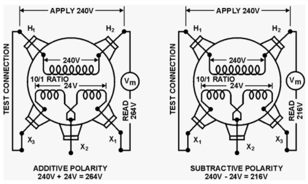
If the value equals the sum of the high and low windings, the transformer is said to have additive polarity. Otherwise, if the meter reads less than the voltage applied the polarity is subtractive.
A 3 phase transformer can be constructed by having 3 primary in three secondary windings on a common magnetic circuit. The 3 single phase CT type Transformers, each with windings on only one leg have their unwound legs combined to provide path for the returning flux. The primaries as well as secondary may be connected in Star Delta. If the primary is energised from three phase supply, the central limb carries. The Fluxes says produced by the 3 phase primary winding. Since the phasor sum of three primary current. At any instances, 0, the sum of three fluxes passing through the central line must be beautiful. Stop home snowflakes exists in the central limband it may be eliminated. This modification gives 3 phase type 3 transformer. In this case, any two legs will act as a return path for the flux in the 3rd leg. For example, if flux is F in one of the leg and at some instance, then the flux is F/ 2 in the opposite direction through the other two legs at the same instant. All the connections of a 3 phase transformer are made inside the case and for delta connected winding three leads are brought out while four star connected. Four leads are brought out.
Procedure
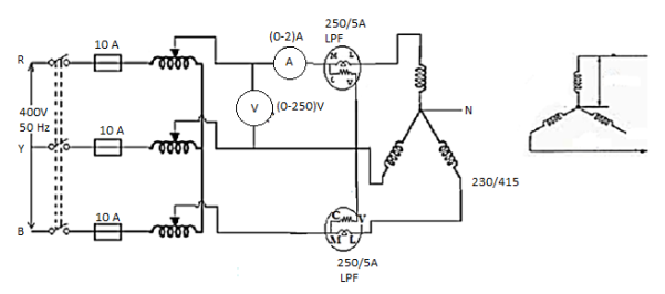
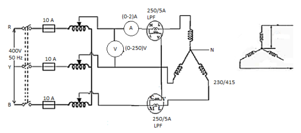
OC TEST
- Connections are made as per the circuit diagram.
- Three phase autotransformer is placed in minimum position and supply is given by DPST. Switch is closed and starting resistance is gradually removed.
- Adjust the autotransformer to get the rated voltage which is read by. Voltmeter which is equal to 230 volts.
- Note the readings, Sum of the readings of two Watt metres to give Core loss.
- Set the AUTOTRANSFORMER to its initial position and switch off the supply.
Circuit Diagram
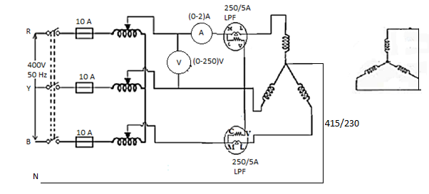
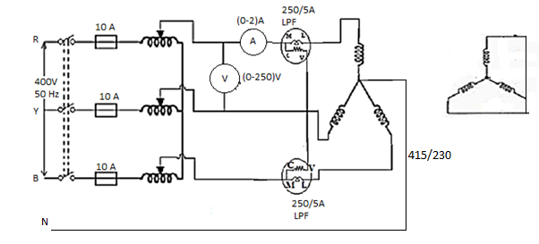
SC TEST
- Connections are made as per the circuit diagram.
- Three phase Autotransformer is placed in minimum position and supply is given by DPST Switch is closed in starting. Resistance is gradually removed.
- Adjust the autotransformer to get the rated current which is read by a metre. In high voltage side which is equal to rated current.
- Note the readings, SUM of the readings of two-Watt metres to give copper loss.
- Set the autotransformer to its initial position and switch off the supply.
Circuit Diagram
Parallel operation of single phase transformer
If the present transformers are not capable of supplying any amount of additional load which is required, then the parallel connections are used to fulfil the requirement. The basic circuit for parallel transformer is shown below.
The condition required for parallel connections: -
- The primary windings of the transformer should be suitable for supply voltage and frequency.
- The connections w.r.t. Polarity of transformer should be proper.
- The voltage ratings of both primaries and secondaries should be identical.
- In order to avoid circulating current the ratio X/R and percentage impendences should be equal in magnitude.
- The transformer that have different KVA ratings should have equivalent impendences inversely proportional to individual KVA rating.
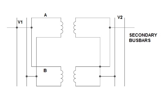
Fig. Parallel Connection of 1-ØTransformer
1) Ideal Case:
Here both the transformers are considered to have same voltage ratio and impedance voltages triangles identical in size and shape.
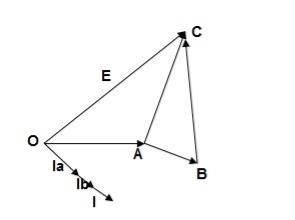
Fig. Phasor for ideal Case
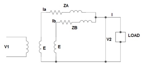
Fig: Ideal Case
I = IA + IB
V2 = E - IAZA
IAZA = IBZB
IA = 
IB = 
E – No load secondary voltage
V2 – Terminal voltage
IA, IB – Currents of each Transformer
2) Equal Voltage Ratio:
Let No-load voltage of each secondary be same E = EA = EB. The change in the secondary is shown below.
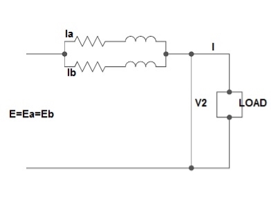
Fig: Equal Voltage Ratio
All values are considered referred to the secondary.
ZA, ZB = impedances of transformer
IA, IB = currents of transformer
V2 = common terminal voltage
IAZA = IBZB = IZAB
ZAB = ZA || ZB
ZA = IZABZA,
IA = 
V2IA = 
V2IB = 
Let V2I × 10-3 = S (Combined Load KVA)
SA = 
SB = 
3) Unequal Voltage Ratios:
Here the no load secondary voltages are unequal.
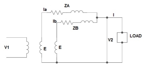
Fig.: Unequal Voltage Ratios
EA, EB = no-load secondary emp
Z1 = load impedance across secondary.
Here circulating current exist as the voltage are unequal (IC).
IC = 
EA = IAZA + V2
EB = IBZB + V2
V2 = IZL = (IA + IB)ZL -----------------(1)
EA = IAZA + (IA + IB)ZL -----------------(2)
EB = IBZB + (IA + IB)ZL -----------------(3)
EA – EB = IAZA – IBZB
IA = 
If ZA and ZB are smaller than ZL.
Substitute IA in equation (3) and solve
IA = 
IB = 
Neglecting ZA ZB in comparison with ZL(ZA + ZB)
We get above equations.
I = IA + IB
I = 
V2 = EA - IAZA and V2 = EB – IBZB
Parallel operation of 3-Ø Transformer
The conditions are same as in case of 1-Ø transformer.
- The voltage ratio must refer to the terminal voltage of primary and secondary.
- The phase displacement between primary and secondary voltages must be same for all transformers.
- The phase sequence must be same.
- All three transformers in 3-Ø transformer bank will be of same construction.
Que 1. What should be the kVA rating of each transformer in V-V bank when 3-Ø balanced load is 50 kVA. If a third transformer is connected for operation find % increase in rating?
→ kVA for each transformer has to be 15%
KVA per transformer = 50/2 × 1.15
= 28.75
Δ-Δ bank rating = 28.75 × 3
= 86.75
Increase = 
= 72.5 %
Que 2. A balanced 3-Ø load of 120 kW at 1100V 0.866 lag p.f is supplied from 1500V, 3-Ø main through 1-Ø transformer connected – (i) Δ-Δ (ii) Y-Y
Find current in the windings of each transformer and p.F at which they operate in each case.
→ (i) Δ-Δ
√3 VLILcosØ = 120,000
√3× 1100 × IL × 0.866 = 120,000
IL = 72.73 A
Secondary line current = 72.73 (= IL)
Secondary phase current =72.73/√3 = 41.99 A
K = 
Primary phase current =41.99/2 = 20.99 A
(ii) Y-Y connection
√3× 1100 × I × 0.866 = 120,000
I = 72.73 A
Secondary phase current = 72.73 A
Primary phase current = 72.73/2 = 41.99 A
Transformer p.f = 86.6 % of 0.866
= 0.75 (lag)
Que 3. Two transformers are required for a Scott connection operating from 410 V 3-Ø supply for supplying two 1-Ø furnaces at 200 V on the two-phase side. If total output is 130 kVA, calculate secondary to primary turn ratio and the winding of each transformer?
→ For main Transformer
Primary voltage = 410 V
Secondary voltage = 200 V

Secondary current = = 325 A
Primary current = 325 ×
= 153.54 A
For teaser Transformer
Primary volts = = 355 V
Secondary volts = 200 V

References
1. I. J. Nagrath, D.P. Kothari, “Electrical Machines,”, Tata McGraw- Hill Publishing
Company Ltd.
2. P.S.Bhimbra,”Electrical Machinery”, Khanna Publishers.
3. P.K. Mukherjee, S. Chakrabvorty, “Electrical Machines”, Dhanpat Rai Publications.
4. P.S. Bhimbra, “Generalized Theory in Electrical Machines”, KhannaPublishers.
5. D C Kulshreshtha, “Basic Electrical Engineering,” The McGraw Hill Higher EducationPrivate Limited, New Delhi.
Unit - 1
Single Phase Transformer
A transformer is a stationary device which works on the principle of Mutual Induction. It is used to transform electric power from one circuit to another having same frequency. It can lower or higher the value of voltage in any circuit but in correspondence to change in current.
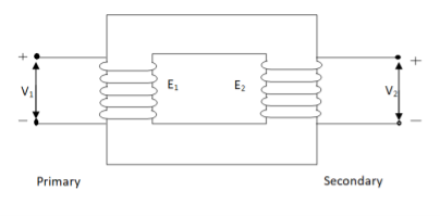
Fig. Ideal Transformer
An ideal transformer has no losses i.e. its winding have no magnetic leakage and no ohmic resistance. Hence, an ideal transformer has only two purely inductive coils wound on a loss-free core.
For above transformer when secondary is open and primary is having input sinusoidal voltage V1. An alternating, current flows due to difference in potential. As primary coil is purely inductive so, Iµ current is drawn through it. This current is very small and logs V1 by 900.
The current Iµ produces magnetic flux φ and hence are in same phase. The flux is linked with both the windings and hence, self-induced emf is produced E1 which is equal and opposite of V1. Similarly, E2 is induced in secondary which is mutually induced emf E2 is proportional to rate of change of flux and number of secondary windings.
The phasor is shown below.
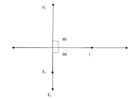
Fig. Phasor for Ideal Transformer
I Ø transformers and electrostatics
Types of transformers
Acc to input supply: I phase and δ phase
Acc to construction: core and shell type
Acc to 0/P step up and step down
Laminated steel core
Material used for core is (silicon steel) it is used for its (high permeability) and (low magnetic reluctance) magnetic field produced is very strong
The core is formed of (stacks of laminated thin steel sheets) which are electrically isolated from each other. They are typically (0.35 to 0.5 mm thick)
We can used 2 ‘L’ shaped sheets or 2 I shaped sheets for laminations
Construction and types
There 2 types of winding
- Concentric or cylindrical
- Sandwiched type
1. Cylindrical
L.V. = low voltage H.V. = high voltage are mounted on same limb to minimum leakage.
L.V. Winding placed inside and H.V. Winding placed outside with (proper insulation between the winding as it is easy to insulated L.V. Winding) than H.V. Winding.
2. Sandwiched
The H.V. And L.V. Winding are divided into no. Of small coils and there small windings are interleaved.
(the top and bottom winding are L.V. Coils because they are close to core)
- Transformer tank: wholes assembly of winding and core placed inside the Transformer tank (sheet metal tank) which is filled with Transformer oil or insulating oil which acts as an (insulator or coolant) MCQ
- Transformer oil: (The function of oil is to remove efficiently the heat generated in core and in winding)
- Moisture should not be allowed which creeps the insulation which achieved by closed Transformer tank.
(To increase cooling surface are tubes or fins are provided)
- Conservator tank: above tank T/F tank there is one small tank in which same empty space is always provided above the oil level. (this space is required for oil to expand or contract due to temperature change) MCQ
However during contraction outside air can have moisture which will deteriorate the insulating properly of oil.
- Breather: the air goes in or out through the breather (To reduce the moisture content of their air. Same drying agents such as (silica gel or) calcium chloride) is used in the breather (The dust particles present in air are also removed by breather)
- Buccholz Relay: (for incipient (slowly increasing) faults
There is pipe connecting rain tank and conservator. On the pipe a protective device called Buccholz Relay is mounted.
When the Transformer is about to be faulty and draw range current the oil becomes very hot and decompose.
During this process different types of gases are liberated.(The Bucchoz Relay get operated by these gases) and gives an alarm to the operator. ɡȴ the fault continues to persist then there lay will trip off main circuit breaker to protect the Transformer.
Explosion Vent:
An explosion Vent or relief value is the bent up pipe filled on the main tank.
(The explosion vent consist of aluminium of oil) when the T/F becomes faulty the cooling oil get decomposed and various types of gases are liberated
(ɡȴ the gas pressure exodus certain level then the aluminium of oil (diagram) in explosion vent will burst) to release pressure. The will save main tank from getting damaged.
Transformer on No Load
When an actual transformer is put on load, we get losses (iron loss) in core and (copper loss) in primary and secondary windings. In NO LOAD (primary current is not purely reactive) the input current has to supply iron loss to core and small amount of copper loss in primary.
The no-load power is W0 = V1 I0 cos Φ0
I0 – no load primary input current
Cos Φ0 – power factor at no-load condition
I0 lags V1 by Φ0< 900
The phasor is shown below.
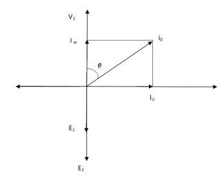
Fig: Phasor for No-Load Transformer
From above figure we can conclude that I0 has two components Iw(in phase with V1) Iµ in quadrature with V1
Iw = I0ws φ0 (iron loss component)
Iµ = I0 cos φ0 (magnetising component)
I0 = I2µ + I2w
Key takeaway
The no-load primary current I0 is very small as compared to full-load primary current. And hence, no-load cu loss is very small. So, primary input is practically equal to iron loss of transformer.
Q1>. A 2500/200 V transformer draws a no-load primary current of 0.5 A and absorbs 400 W. Find magnetising and loss currents.
Sol: Iron-loss current = No load input(W) / Primary voltage
= 400/2500 = 0.16 A
I20 = I2w + I2µ
Iµ = √I20 – I2w
= √ (0.5)2 – (0.16)2
Iµ = 0.473 A
Q2>. A 1-φ transformer has 1000 turns on primary and 200 on secondary. The no load current is 4 amp at p.f of 0.2 lagging. Find primary current and pf when secondary current is 280 A at pf of 0.6 lagging.
Sol: cos-1 0.6 = 53.130 (sin φ = 0.8)
I2 = 280/-53.130A
Φ = cos-1 0.2 = 78.50
Sin φ = 0.98
I1 = I0 + I’2
I’2 = (I2/K) ( -53.130
K = N1/N2 = 1000/200 = 5
I’2 = 280/5 (-53.130
I’2 = 56(-53.130
I1 = I0 + I’2
= 4(0.20 – j0.98) + 56(0.6 – j0.8)
= 0.80 – j3.92 + 33.6 – j44.8
I1 = 34.4 – j48.72
I1 = 59.64 ( -54.770
I lags supply voltage by 54.770
Transformer On Load
When secondary winding is loaded then the current in it is setup(IQ). The current I2 is in phase with V2 if load is non-inductive it lags if load is inductive & leads if load is capacitive.
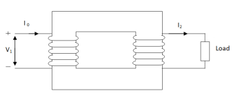
Fig: Transformer with Secondary connected to Load
An mmf is set up at secondary and hence φ2 flux is induced which is in opposition to main flux φ due to I0. The flux φ2 weaken φ and hence primary back emf E1 is reduced. An additional primary current I’2 is introduced exactly at instance when I2 is introduced. So, that magnetic effect of I2 is neutralized by I’2.
Φ2 = φ’2
N2 I2 = N1 I’2
I’2 = N2/N1 x I2 = K2 I2
The phasor is shown below,
(a)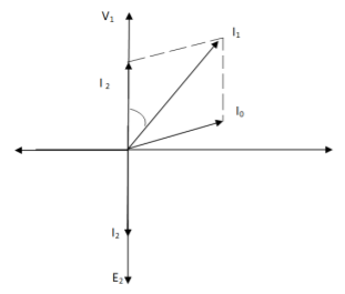
(b)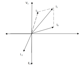
Fig. Phasor for Load Transformer
From fig (a) (non – inductive load)
I2 is in phase with E2(=V2)
I’2 is antiphase with but equal in magnitude
I1 is vector sum of I’2 and I0, but lags V1
From fig (b), Inductive load
I2 lags V2
I’2 is not in phase with I2 but equal in magnitude
I1 is vector sum of I’2& I0 but lags V1
Key takeaway
I’2/I2 = I1/I2 = N2/N1 = K
Q>. A 1- φ transformer with ratio of 440/110-V takes a no-load current of 6 A at 0.3 pf lagging. If secondary supplies 120 A at pf of 0.8 lagging. Find current taken by primary.
Sol>.
Cos φ2 = 0.8
Φ2 = 36.540
Cos φ0 = 0.3
Φ0 = 72.540
K = V2/V1 = 110/440 = ¼
I’2 = KI2 = 120 x ¼ = 30 A
I0 = 6A
Angle between I0& I’2
= 72.54 – 36.54
= 35.670
From vector diagram,
I1 = √(62 + 302 + 2 x 6 x 30 cos 35.67)
I1 = 35.05 A
- Losses in a Transformer [6m]
There are 2 types of losses occurring in a transformer
A) 1. Core loss or Iron loss
B) 2. Copper loss
- Core losses:
- This loss is due to the reversal of flux
- The flux set up in the core is dependent on the i/p supply as the i/p supply is constant in magnitude the flux set up will be constant and core losses are also constant.
- Core losses are voltage dependent loss they can be subdivided in 2
1. Hysteresis loss
2. Reedy current loss
1. Hysteresis loss: The iron loss occurring in the core of T/F due to the Hysteresis curve of the magnetic material used for core is called as Hysteresis loss.
Hysteresis curve is the curve as loop which shows the properly of magnetic material to lag the flux density B behind the field Intensely H
Above are the 3 different loops (Hysteresis of 3 diff. Materials)
the selection of magnetic material for the construction of core depends upon Hysteresis loop of that material having tall and narrow Hysteresis loop is selected for the T/F core
Eg: silicon Steel
Hysteresis loss depends on fold factor
PH = KH. Bm1.67 F V – watts
Where KH = constant (Hyst)
Bm = max Flux density
F = Frequency
V = Volume of core.
2. Reedy current loss:
This loss is due to the flow of reedy (circular) current in the core caused by induced emf in core
PE = Ke Bm2 f2 t2 v – watts
Where
Ke = reedy current const.
t = thickness of core
It can be reduced by using stacks of laminations instead of solid core
B] Copper loss: PCU
The Copper loss is due to resistance of the primary and secondary winding
It is load dependent / current dependent loss
As load on a transformer is variable (changing) current changes copper loss is a variable loss
Primary secondary
Total C is loss = I12R12 + I22 R22
Copper loss depends upon load on T/F and is proportional to square of load current or KVA rating of transformer
PCU I2 (KVA)2
F.L = full load
PCU (at half load) = (1/2)2 PCu F.L
= (0.5)2 PCU F.L.
Or PCu (x load) = (x) 2 PCu F.L
The basic transformer and its equivalent circuit both are shown below,
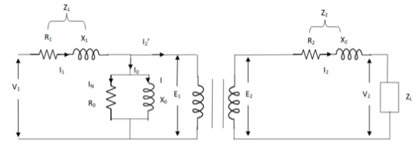
Fig. Equivalent Transformer Circuit
Iµ - magnetising component of current
Iw = working component
R0 – Non- inductive resistance
I0 – No load current
X0 = E1/I0. R0 = E1/Iw
E2/E1 = N2/N1 = K
E’2 = E2/K = E1
V’2 = V2/K
I’2 = K I2
The total equivalent circuit is again given as,
But the above circuit is exact equivalent but harder to solve so, it can be further simplified as,
Z = Z1 + Zm || ( Z’2 + Z’L )
= Z1 + Zm(Z’2 + Z’L)/Zm + (Z’2 + Z’L)
Z’2 = R’2 + jX’2
Zm = impedance of exciting circuit
V1 = I1[ Z1 + Zm(Z’2 + Z’L) / Zm + (Z’2 + Z’L) ]
Testing-OC and SC Test
(1). Open circuit test
(2). Short circuit test
(1). OPEN CIRCUIT TEST:
Basically these tests are performed to find the basic parameters of transformers. The open circuit test is performed to determine no-load loss(core loss) and no-load current I0 which is helpful in finding X0 and R0.
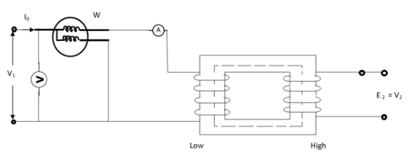
Fig. Open Circuit Test
In this test the high voltage winding is left open and the other is connected to supply.
A wattmeter W, voltmeter V and an Ammeter A are connected to L.V. Winding.
Due to applied voltage in primary, flux is set up in core, and hence normal iron loss occurs. This is recorded in Wattmeter. The current I0 is measured by Ammeter A.
Wattmeter reading represents core loss under no-load condition.
The wattmeter reading will be given as
W = V1 I0 cos φ0
Iµ = I0 Sin φ0
Iw = I0 cos φ0
X0 = V1/Iµ, R0 = V1/Iw
At no load I0 ≈ Iµ
I0 = V1 Y0
Y0 – Exciting Admittance
W = V21 G0
G0 – Exciting conductance
B0 = √ Y20 – G20
B0 – Exciting susceptance
(2). SHORT CIRCUIT TEST:
This test is used to determine
(i). Equivalent Impedance (Z01, Z02), leakage reactances (X01 or X02), Total resistance (R01, R02).
(ii). Cu losses are also calculated at full load.
(iii). The regulation of transformer can be determined as Z01, Z02 can be calculated.
Here low voltage is short circuited. And the supply is through high voltage (primary here).
As applied voltage is small, hence the flux φ induced is also small.
As core losses are very small, the wattmeter reading is the cu-loss at full load for whole transformer.
The equivalent circuit is shown below,
Z01 = Vsc/I1
Vsc = voltage to circulate rated load current
W = I21 R01
R01 = W / I21
X01 = √ Z201 – R201
R’2 = R01 – R1
Examples
Q1>. The primary and secondary windings of a 30 KVA, 5000/330 V, 1- φ transformer having resistance of 15 Ω and 0.02 Ω. The reactance referred to primary is 34 Ω. Calculate primary voltage required to circulate full-load current when the secondary is S.C. Also calculate the pf?
Sol. K = 330/5000 = 33/500
X01 = 34 Ω
R01 = R1 + R2/K2 = 15 + 0.02(500/33)2 = 19.59 Ω
Z01 = √ R201 – X201
= √ 19.592 + 342
Z01 = 39.23 Ω
F. L I1 = 30,000/5000 = 6A
Vsc = I1 Z01 = 6 x 39.23 = 235.4 V
S.C. Power factor = R01 / Z01 = 19.59/39.23 = 0.5
Q2). In no-load test of 1- φ transformer, the test data are
Primary voltage = 200 V,
Resistance of primary = 0.6 Ω
Secondary voltage = 100 V
Primary current = 0.6 A
Power input = 30 W
Find (a) Turns ratio (b) Magnetising component of no-load current (c) Working component (d) Iron loss
Sol>. (a). N1/N2 = 200/100 = 1
(b). W = V1 I0 cos φ0
Cos φ0 = 30/200 x 0.6 = 0.25, sin φ0 = 0.97
Iµ = I0 sin φ0 = 0.6 x 0.97 = 0.58 A
©. Iw = I0 Cos φ0 = 0.6 x 0.25 = 0.15 A
(d). Cu loss = I20 R1 = (0.6)2 x 0.6 = 0.216 W
Iron loss = 30 – 0.216 = 29.78 W
Q.3 Obtain the secondary voltage when delivered 10 KW at 0.8 PF.logging . The primary volt be 220v. The 300/600 v 50H2, 1-  Transformer has following test results.
O.C test-:200v, 0.8A 70W-L.V side
S.C test-: 12V,10A 80W-HV side
Sol: O.C TEST
W= V1I0COS θ0
70=200*0.8*Cos ∅0
Cos ∅0= 0.436
Sin ∅0=0.899
IW = I0 COS ∅0=0.8*0.436=0.35A
Iμ = I0 sin ∅0 = 0.8*0.899=0.72A
R0 =  =571.4 Ω
X0 = =
= =277.8𝛺
S.C TEST:
Z02= =
= =1.2A
=1.2A
K= =2
=2
Z01= =
= =0.3 Ω
I22R02=W
RO2= =0.7Ω
=0.7Ω
R01= =
= =0.175 Ω
X01= 
= 
X01 = 0.244 Ω
Output KVA =  =12.5
=12.5
I2=  = 20.83A
Z02=1.2A R02=0.7𝛺
X02=  =0.975𝛺
Total transformer drop refereed to secondary
= I2 (RO2COS ∅ + X02Sin ∅)
= 20.83(0.7*0.8+0.975*0.6)
= 23.85v
V2= 600 - 23.85=576.15v
Voltage Regulation:
It can be explained in terms of various parameter of transformer.
(1). When transformer has constant primary voltage.
In this case secondary voltage decreases
0V2 = No-load secondary terminal voltage
0V2 = E2 = EK1 = KV1
V2 = secondary voltage on full-load.
Voltage Regulations is change in secondary terminal voltage from no-load to full load per unit full load voltage.
% regn down = 0V2 – V2/0V2 x 100
% regn up = 0V2 – V2/V2 x 100
(2). Voltage regulation in terms of primary values.
The secondary no-load terminal voltage as referred to primary is E’2 = E2/K = E1 = V1
For secondary full load voltage referred to primary is V’2 = V2/K
% regn = V1 – V’2/V1 x 100
% regn = I1 R01 cosφ + I1 X01 sinφ / V1 x 100
(3). As the transformer is loaded, to maintain a constant output voltage, the primary voltage should be increased. Here the regulation is given as
% regn = V’1 – V1 / V1 x 100
It can also be defined as the change in primary voltage from no-load to full-load at given power factor to maintain a constant output per unit primary voltage.
Example
Q. A – 100 KVA transformer has 500 turns on primary and 80 turns on secondary. The primary and secondary resistances are 0.3 and 0.01 Ω respectively and the corresponding leakage reactances are 1.1 and 0.035 Ω. The supply voltage is 2400 V. Find
(i). Equivalent impedance referred to primary
(ii). Voltage regulation and the secondary terminal voltage for full load having pf 0.8 lagging?
Sol. Equivalent impedance referred to primary
Z01 = √R201 + X201 = R01 + jX01
R01 = R1 + R2/K2 = 0.3 + 0.01/K2 = 0.69 Ω
K = 80/500 = 4/25
X01 = X1 + X2/K2 = 1.1 + 0.035/(0.16)2 = 2.467 Ω
Z01 = 0.69 + j2.46
(ii). Secondary terminal voltage Z02 = K2 Z01
Z02 = 0.018 + j 0.063
= 0.065 ( 74.050
No-load secondary voltage = KV1
= 0.16 x 2400 = 384 V
I2 = 100 x 103/384 = 260.42 A
Full load voltage drop referred to secondary
= I2 (R02 cosφ– X02 Sinφ)
Cosφ = 0.8
Φ = 36.860
Sinφ = 0.6
= 260.42(0.018 x 0.8 – 0.063 x 0.6)
= - 6.094 V
% regn = -6.094/384 x 100
= -1.587
Secondary terminal voltage on-load
= 384 – (-6.094)
= 390.09 V
Basically, efficiency is defined as
n = output/input
But for transformer there are small amount of losses so the improved way to find efficiency is
n = output/output + losses
n = output/output + cu loss + iron loss
Or n = Input – losses/Input
= 1 – Losses/Input
For n to be maximum dn/dI1 = 0
(Ww) cu loss = I21 R01 or I22 R02
Iron loss = Hysteresis loss + Eddy current loss
= Wn + We = Wi
n = Input – losses/Input
Primary Input = V1I1 Cosφ1
n = V1 I1 Cosφ1 – losses/V1 I1 cos φ1
n = V1 I1 cos φ1 – I21 R01 – Wi / V1I1 cosφ1
= 1 – I1R01/V1cosφ1 – Wi/V1I1cosφ1
Differentiating w.r.t I1 both sides of above equation we have
Dn/dI1 = 0 – R01/V1cosφ1 + Wi/V1I21 Cosφ1
For max value dn/dI1 = 0
R01/V1cosφ1 = Wi/V1I21 cosφ1
Wi = I21 = I21 R01
Hence,
Wi = Wcu
Iron loss = copper loss
The value of output current for maximum efficiency will be
I2 = √Wi/R02
The maximum efficiency can also be given as,
nmax = full load x √ Iron loss / F.L .cu loss
Or
nmax = R’ x full load KVA x pf / R’ x full load KVA x pf + Wi + Wcu x 100
R’ = ratio of actual to full load KVA
Wi = iron loss (KW)
Wcu = copper loss (KW)
Example
Q1). In a 50 KVA, 2200/200 V, 1-φ transformer, the iron and full-load copper losses are 400 W and 450 W respectively. Calculate n at unity power factor on (i). Full load (ii). Half-full load?
Sol. (i). Total loss = 400 + 450 = 850 W
F.L output at unity power factor = 50 x 1
= 50 KVA
n = 50 / 50 + .850 = 50/50.850 = 0.98 = 98%
(ii). Half full load, unity pf
= 50 KVA/2 = 25 KVA
Cu loss = 400 x (1/2)2 = 100 W
Iron loss is same = 450 W
Total loss = 100 + 450 = 550 W
n = 25/25 + 0.55 = 25/25.55 = 0.978 = 97.8 %
Q>. A 40 KVA 440/220 V, 1- φ, 50 Hz transformer has iron loss of 300 W. The cu loss is found to be 100 W when delivering half full-load current. Determine (i) n when delivering full load current at 0.8 lagging pf (ii) the percentage of full-load when the efficiency will be max.
Sol. Full load efficiency at 0.8 pf
= 40 x 0.8/(40 x 0.8) + losses
Full load cu loss = (440/220)2 x 100
= 400 W
Iron loss = 400 + 300
= 700 W
n = 40 x 0.8/(40 x 0.8) + 0.7 = 97.8 %
(ii). KVA for maximum / F.L KVA = √ iron loss / F.L cu loss
= √300/400 = 0.866
Usually transformer efficiency is given as
n= 
But there are few transformers in which their primary winding is energized for whole day. And their secondary supplier no load. So, the core loss occurs for whole day and loss occurs only when transformer is loaded. Now n becomes.
nall – day = 
Q. Find all day efficiency of 500KVA distribution transformer whose loss and iron loss are 5.5 kW and 4.5 kW. During day it is loosed as
No of hours | Loaded in kw | Power factor |
6 | 400 | 0.8 |
10 | 300 | 0.75 |
4 | 100 | 0.8 |
4 | 0 | - |
|
|
|
Solution: Cu loss at full load of 500 KVA =5.5KW
Load at 400kw 0.8 pf =  =500KVA
Load at 300kw 0.75 pf =  =400KVA
Load loss at 400 KVA =0.8= =125KVA
Cu Loss at 400KVA =5.5 *
=3.52 KW
Cu Loss at 125KVA=5.5*( )2
)2
=0.345KW
Total Cu loss in 24 hr = (6*5.5) + (10*3.52) + (4*0.345) + 0
= 66.38kwh
Iron loss in 24hr =24*4.5 =108 kwh
Total transformer loss =66.38+108
=174.38 kwh
Transformer output 24hr= (6*400) + (10*300)
= (4*100)
=5800 kwh
nall – day = 
=  =0.97
=0.97
The polarity test of a transformer can be done by measuring only voltage at no load. The basic connections are shown in below circuit.
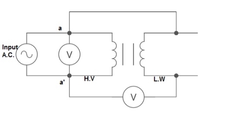
Fig: Polarity Test
From above circuit input is applied for one winding. There is another voltage ‘V’ measured between one winding from each terminal. If voltage V’ > V, polarity is additive. If voltage V’ < V, polarity is subtractive.
An auto Transformer is a special types of transformer such that a part of the winding is common to both primary as well as secondary
It has only One winding wended on a laminated magnetic core
With the help of auto Transformer the voltage can be stepped up and stepped down at any desired value
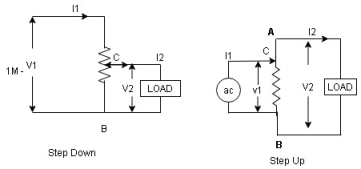
Figure. Auto Transformer
Fig A shows auto T/F as step down T/F variable terminal B C is connected to load and it acts as secondary wdg.
The position of point C is called as topping point can be selected as per requirement
Fig. B show auto T/F as step up T/F variable terminal B C is connected to supply side ie ac side and it acts as secondary winding
The operating principle of auto Transformer is same as that of 2 winding Transformer
Advantages
- Weight of copper required in an auto Transformer is always loss than that of the conventional 2 winding Transformer and hence it is chaper
- Com[act in size and loss costly.
- Losses taking place in Transformer is reduced hence efficiency is higher than conventional Transformer.
- Due to reduced resistance, voltage, regulation is better than conventional T/F.
Disadvantage:
As low voltage and high voltage sides are not separate then there is always risk of electric shocks when use for high vtg.
Applications
- Starting squirrel cage induction motor and synchronous motor.
- Auto transformer as dimmer stat
- Used as various ac to vary a. c Voltage
As the supply is in 3-phase so we need this transformer. Its alternating voltage and currents differ in phase by 120 degrees.
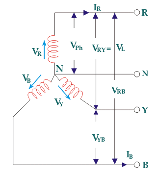
Fig: Three phase Transformer
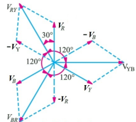
Fig: Line and phase voltage
Construction:
a) Core Type:
The construction of a core type three phase transformer is as shown in the figure. The core consists of three legs or limbs. The core is made up of thin laminated sheets to reduce eddy current losses. Each limb has primary and secondary windings in cylindrical shape (former wound) arranged concentrically. The construction is shown in the figure.
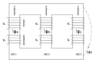
Fig: Core type 3-phase transformer
b) Shell Type:
In a shell type three phase transformer, three phases are more independent than they are in core type. Each phase has its individual magnetic circuit. The construction of shell type three phase transformer is illustrated in the figure at right. The construction is similar to that of three single phase shell type transformers kept on the top of each other.
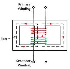
Fig: Shell Type 3-phase Transformer
Connection
Star – star or Y/Y connection: -
The below figure shows transformers connected in Y/Y on both primary and secondary sides. The ratio of line voltage and transformation ratio of line voltage and transformation ratio of both primary and secondary of each transformer in same. Hence the phase voltage VP =  . VLine (line voltage)
This connection works only if the load is balanced.
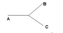
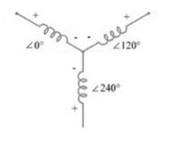
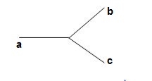
Fig: Three phase transformer Y-Y connection
- The effect of unbalanced load can be balanced by placing single load between a and n on secondary.
- Power to load is supplied by primary side A.
- As, A is in series with B and C and has b and c open on secondary, so it cannot supply required power.
- Now, B and C acts as high impedance in this condition, allowing very less flow of current in A.
- A low resistance can be connected between a and n which is approaching to short circuit. So, small current flows.
- Hence, EAN will reduce to zero but EBN and ECN will rise to full primary line voltage.
- The above shown connection is most economical for small, high-voltage transformers because the number of turns per phase and the amount of installation required is minimum.
- One more advantage is that the installation is stressed to the extent of line to neutral voltage i.e., 58% of line voltage.
- For having a sine wave voltage at output, it is necessary that sine wave of flux should be in the core. To fulfil this, we require third harmonic component of exciting current.
- To attain this if primary neutral is isolated then triple current cannot be attained. So, the best way is to provide a territory winding to each transformer of 1000 kVA rating.
Delta – Delta or Δ – Δ connection: -
- In this connection the ratio of transformation between both primary and secondary line voltage is same.
- There is no internal phase shift between phase and line voltages on either side as it was in Y-Y connection.
- The third harmonic component of current can flow in the Δ-connected transformer primaries.
- The balancing of load is easy unlike Y-Y connections.
- As the phases are 120˚ apart w.r.t. Third harmonic, the flux is sinusoidal which results in sinusoidal voltages.
- If anyone transformer becomes disabled. The system can continue to operate in open delta or V-V connection.
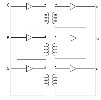
Fig: Δ-Δ connection
Wye / Delta or Y/Δ connections: -
- It is mainly used at the subtraction where the voltage is to be stopped down.
- Primary winding is Y connected and the ratio of secondary & primary line voltage is 1/
 .
. - There is 30˚Ø-shift between primary & secondary of line voltage.
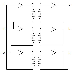
Fig: Y/Δ connection
Delta/Wye or Δ/Y connection:
- It is used where we need to stop up the voltage.
- The primary and secondary line voltages and line currents are out of phase with each other by 30˚.
- The ratio of secondary to primary voltage is
 times of the transformation ratio of each transformer.
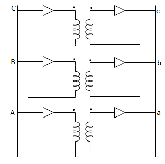
Fig: Δ-Y connection
Comparative features:
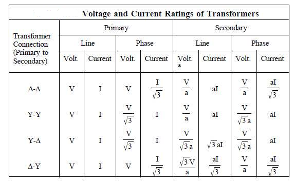
*a = N1/N2; 
Key takeaway
Que 1. A 3-Ø, 50Hz transformer has delta connected primary and star-connected secondary, the line voltage being 20,000 V and 500 V respectively. The secondary has a star connected balanced load at 0.8 lagging p.f. The line current of primary side is 5A. Determine the current in each coil of the primary and secondary line. Also find the output of the transformer?
→Phase voltage on primary side = 20,000 V
Phase voltage on secondary =  V
V
K = 
Primary phase current = 
Secondary phase current = 
= 
= 200 A
Output =  VLILcosØ
= 
= 138.56 kW
Que 2. A 100 kVA, 3Ø, 50 Hz, 3500/500 V transformer is Δ – connected on the h. V side and Y-connected on the L.V. Side. The resistance of h.V. Winding is 3.5 Ω / phase and that of L.V is 0.02 Ω per phase. Calculate the iron losses of the transformer at normal voltage and frequency if its full load efficiently be 95.1 % at 0.8 p.f.?
→Full load output = 100 × 0.8 = 80 kW
Input =  kW
kW
Total loss = Input – Output
= 83.2 – 80
= 3200 kW
K = 
K = 
= 
RO2 = R2 + k2R1
= 
= 0.044 Ωs
Full-load secondary phase current I2
= 
= 115.4 A
Total Cu Loss = 3I22RO2
= 3 × 0.044 × (115.4)2
= 1760 W
Iron Loss = Total loss – Cu Loss
= 3200 – 1760
= 1440 W
Phasor Group
- The vector for the high voltage winding is taken as the reference vector. Displacement of the vectors of other windings from the reference vector, with anticlockwise rotation, is represented by the use of clock hour figure.
- IS: 2026 (Part 1V)-1977 gives 26 sets of connections star-star, star-delta, and star zigzag, delta-delta, delta star, delta-zigzag, zigzag star, zigzag-delta. Displacement of the low voltage winding vector varies from zero to -330° in steps of -30°, depending on the method of connections.
- Hardly any power system adopts such a large variety of connections. Some of the commonly used connections with phase displacement of 0, -300, -180″ and -330° (clock-hour setting 0, 1, 6 and 11).
- Symbol for the high voltage winding comes first, followed by the symbols of windings in diminishing sequence of voltage. For example a 220/66/11 kV Transformer connected star, star and delta and vectors of 66 and 11 kV windings having phase displacement of 0° and -330° with the reference (220 kV) vector will be represented As Yy0 – Yd11.
- The digits (0, 1, 11 etc) relate to the phase displacement between the HV and LV windings using a clock face notation. The phasor representing the HV winding is taken as reference and set at 12 o’clock. Phase rotation is always anti-clockwise. (International adopted).
- Use the hour indicator as the indicating phase displacement angle. Because there are 12 hours on a clock, and a circle consists out of 360°, each hour represents 30°.Thus 1 = 30°, 2 = 60°, 3 = 90°, 6 = 180° and 12 = 0° or 360°.
- The minute hand is set on 12 o’clock and replaces the line to neutral voltage (sometimes imaginary) of the HV winding. This position is always the reference point.
Example:
- Digit 0 =0° that the LV phasor is in phase with the HV phasor
Digit 1 =30° lagging (LV lags HV with 30°) because rotation is anti-clockwise. - Digit 11 = 330° lagging or 30° leading (LV leads HV with 30°)
- Digit 5 = 150° lagging (LV lags HV with 150°)
- Digit 6 = 180° lagging (LV lags HV with 180°)
- When transformers are operated in parallel it is important that any phase shift is the same through each. Paralleling typically occurs when transformers are located at one site and connected to a common bus bar (banked) or located at different sites with the secondary terminals connected via distribution or transmission circuits consisting of cables and overhead lines.
Phase Shift (Deg) | Connection | ||
0 | Yy0 | Dd0 | Dz0 |
30 lag | Yd1 | Dy1 | Yz1 |
60 lag |
| Dd2 | Dz2 |
120 lag |
| Dd4 | Dz4 |
150 lag | Yd5 | Dy5 | Yz5 |
180 lag | Yy6 | Dd6 | Dz6 |
150 lead | Yd7 | Dy7 | Yz7 |
120 lead |
| Dd8 | Dz8 |
60 lead |
| Dd10 | Dz10 |
30 lead | Yd11 | Dy11 | Yz11 |
|
|
|
|
- The phase-bushings on a three phase transformer are marked either ABC, UVW or 123 (HV-side capital, LV-side small letters). Two winding, three phase transformers can be divided into four main categories
Group | O’clock | TC |
Group I | 0 o’clock, 0° | Delta/delta, star/star |
Group II | 6 o’clock, 180° | Delta/delta, star/star |
Group III | 1 o’clock, -30° | Star/delta, delta/star |
Group IV | 11 o’clock, +30° | Star/delta, delta/star |
Minus indicates LV lagging HV, plus indicates LV leading HV | ||
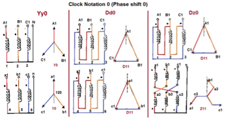
Fig. Clock Notation: 0
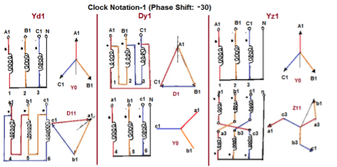
Fig. Clock Notation: 1
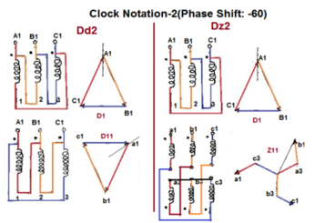
Fig. Clock Notation: 2
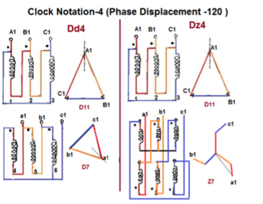
Fig. Clock Notation: 4
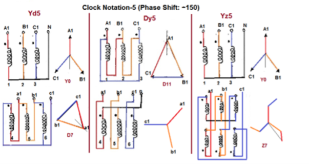
Fig. Clock Notation: 5
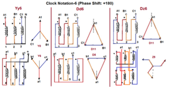
Fig. Clock Notation: 6
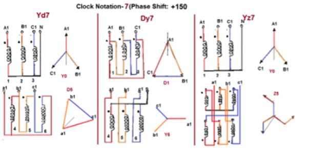
Fig. Clock Notation: 7
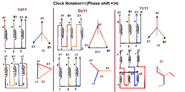
Fig. Clock Notation: 11
Key takeaway
Vector Groups are the IEC method of categorizing the primary and secondary winding configurations of 3-phase transformers. Windings can be connected as delta, star, or interconnected-star (zigzag). Winding polarity is also important, since reversing the connections across a set of windings affects the phase-shift between primary and secondary.
Examples
Que 1. A 3-Ø, 50Hz transformer has delta connected primary and star-connected secondary, the line voltage being 20,000 V and 500 V respectively. The secondary has a star connected balanced load at 0.8 lagging p.f. The line current of primary side is 5A. Determine the current in each coil of the primary and secondary line. Also find the output of the transformer?
→ Phase voltage on primary side = 20,000 V
Phase voltage on secondary =  V
V
K = 
Primary phase current = 
Secondary phase current =
= 
= 200 A
Output =  VLILcosØ
= 
= 138.56 kW
Que 2. A 100 kVA, 3Ø, 50 Hz, 3500/500 V transformer is Δ – connected on the h. V side and Y-connected on the L.V. Side. The resistance of h.V. Winding is 3.5 Ω / phase and that of L.V is 0.02 Ω per phase. Calculate the iron losses of the transformer at normal voltage and frequency if its full load efficiently be 95.1 % at 0.8 p.f.?
→ Full load output = 100 × 0.8 = 80 kW
Input =  kW
kW
Total loss = Input – Output
= 83.2 – 80
= 3200 kW
K = 
K = 
= 
RO2 = R2 + k2R1
= 0.02 + 
= 0.044 Ωs
Full-load secondary phase current I2
= 
= 115.4 A
Total Cu Loss = 3I22RO2
= 3 × 0.044 × (115.4)2
= 1760 W
Iron Loss = Total loss – Cu Loss
= 3200 – 1760
= 1440 W
We can easily test for transformer polarity by using a reduced voltage source to excite the primary winding. First, jumper the H1 terminal to the X1 terminal of the transformer. Next, connect a volt meter between the H2 and X2 terminal. Apply a reduced voltage across H1 and H2, and record the voltage measured on the meter.
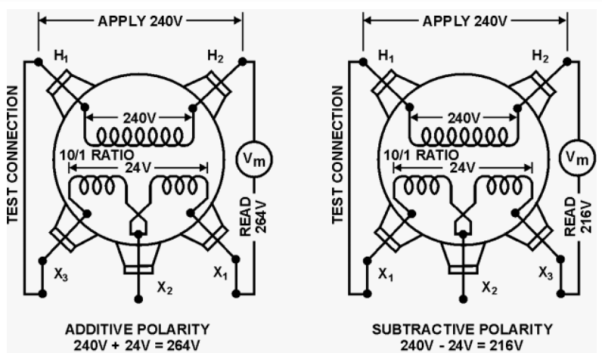
If the value equals the sum of the high and low windings, the transformer is said to have additive polarity. Otherwise, if the meter reads less than the voltage applied the polarity is subtractive.
A 3 phase transformer can be constructed by having 3 primary in three secondary windings on a common magnetic circuit. The 3 single phase CT type Transformers, each with windings on only one leg have their unwound legs combined to provide path for the returning flux. The primaries as well as secondary may be connected in Star Delta. If the primary is energised from three phase supply, the central limb carries. The Fluxes says produced by the 3 phase primary winding. Since the phasor sum of three primary current. At any instances, 0, the sum of three fluxes passing through the central line must be beautiful. Stop home snowflakes exists in the central limband it may be eliminated. This modification gives 3 phase type 3 transformer. In this case, any two legs will act as a return path for the flux in the 3rd leg. For example, if flux is F in one of the leg and at some instance, then the flux is F/ 2 in the opposite direction through the other two legs at the same instant. All the connections of a 3 phase transformer are made inside the case and for delta connected winding three leads are brought out while four star connected. Four leads are brought out.
Procedure
OC TEST
- Connections are made as per the circuit diagram.
- Three phase autotransformer is placed in minimum position and supply is given by DPST. Switch is closed and starting resistance is gradually removed.
- Adjust the autotransformer to get the rated voltage which is read by. Voltmeter which is equal to 230 volts.
- Note the readings, Sum of the readings of two Watt metres to give Core loss.
- Set the AUTOTRANSFORMER to its initial position and switch off the supply.
Circuit Diagram
SC TEST
- Connections are made as per the circuit diagram.
- Three phase Autotransformer is placed in minimum position and supply is given by DPST Switch is closed in starting. Resistance is gradually removed.
- Adjust the autotransformer to get the rated current which is read by a metre. In high voltage side which is equal to rated current.
- Note the readings, SUM of the readings of two-Watt metres to give copper loss.
- Set the autotransformer to its initial position and switch off the supply.
Circuit Diagram
Parallel operation of single phase transformer
If the present transformers are not capable of supplying any amount of additional load which is required, then the parallel connections are used to fulfil the requirement. The basic circuit for parallel transformer is shown below.
The condition required for parallel connections: -
- The primary windings of the transformer should be suitable for supply voltage and frequency.
- The connections w.r.t. Polarity of transformer should be proper.
- The voltage ratings of both primaries and secondaries should be identical.
- In order to avoid circulating current the ratio X/R and percentage impendences should be equal in magnitude.
- The transformer that have different KVA ratings should have equivalent impendences inversely proportional to individual KVA rating.
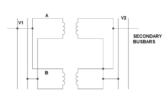
Fig. Parallel Connection of 1-ØTransformer
1) Ideal Case:
Here both the transformers are considered to have same voltage ratio and impedance voltages triangles identical in size and shape.
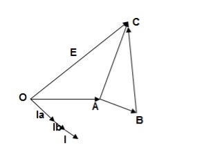
Fig. Phasor for ideal Case
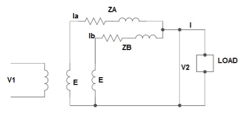
Fig: Ideal Case
I = IA + IB
V2 = E - IAZA
IAZA = IBZB
IA = 
IB = 
E – No load secondary voltage
V2 – Terminal voltage
IA, IB – Currents of each Transformer
2) Equal Voltage Ratio:
Let No-load voltage of each secondary be same E = EA = EB. The change in the secondary is shown below.
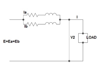
Fig: Equal Voltage Ratio
All values are considered referred to the secondary.
ZA, ZB = impedances of transformer
IA, IB = currents of transformer
V2 = common terminal voltage
IAZA = IBZB = IZAB
ZAB = ZA || ZB
ZA = IZABZA,
IA = 
V2IA = 
V2IB = 
Let V2I × 10-3 = S (Combined Load KVA)
SA = 
SB = 
3) Unequal Voltage Ratios:
Here the no load secondary voltages are unequal.
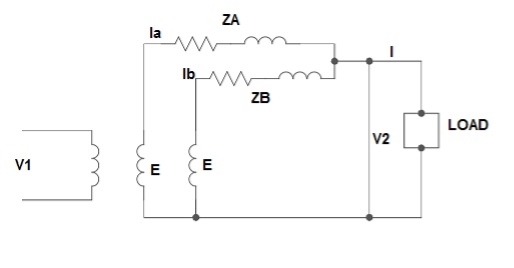
Fig.: Unequal Voltage Ratios
EA, EB = no-load secondary emp
Z1 = load impedance across secondary.
Here circulating current exist as the voltage are unequal (IC).
IC = 
EA = IAZA + V2
EB = IBZB + V2
V2 = IZL = (IA + IB)ZL -----------------(1)
EA = IAZA + (IA + IB)ZL -----------------(2)
EB = IBZB + (IA + IB)ZL -----------------(3)
EA – EB = IAZA – IBZB
IA = 
If ZA and ZB are smaller than ZL.
Substitute IA in equation (3) and solve
IA = 
IB = 
Neglecting ZA ZB in comparison with ZL(ZA + ZB)
We get above equations.
I = IA + IB
I = 
V2 = EA - IAZA and V2 = EB – IBZB
Parallel operation of 3-Ø Transformer
The conditions are same as in case of 1-Ø transformer.
- The voltage ratio must refer to the terminal voltage of primary and secondary.
- The phase displacement between primary and secondary voltages must be same for all transformers.
- The phase sequence must be same.
- All three transformers in 3-Ø transformer bank will be of same construction.
Que 1. What should be the kVA rating of each transformer in V-V bank when 3-Ø balanced load is 50 kVA. If a third transformer is connected for operation find % increase in rating?
→ kVA for each transformer has to be 15%
KVA per transformer = 50/2 × 1.15
= 28.75
Δ-Δ bank rating = 28.75 × 3
= 86.75
Increase = 
= 72.5 %
Que 2. A balanced 3-Ø load of 120 kW at 1100V 0.866 lag p.f is supplied from 1500V, 3-Ø main through 1-Ø transformer connected – (i) Δ-Δ (ii) Y-Y
Find current in the windings of each transformer and p.F at which they operate in each case.
→ (i) Δ-Δ
√3 VLILcosØ = 120,000
√3× 1100 × IL × 0.866 = 120,000
IL = 72.73 A
Secondary line current = 72.73 (= IL)
Secondary phase current =72.73/√3 = 41.99 A
K = 
Primary phase current =41.99/2 = 20.99 A
(ii) Y-Y connection
√3× 1100 × I × 0.866 = 120,000
I = 72.73 A
Secondary phase current = 72.73 A
Primary phase current = 72.73/2 = 41.99 A
Transformer p.f = 86.6 % of 0.866
= 0.75 (lag)
Que 3. Two transformers are required for a Scott connection operating from 410 V 3-Ø supply for supplying two 1-Ø furnaces at 200 V on the two-phase side. If total output is 130 kVA, calculate secondary to primary turn ratio and the winding of each transformer?
→ For main Transformer
Primary voltage = 410 V
Secondary voltage = 200 V

Secondary current = = 325 A
Primary current = 325 ×
= 153.54 A
For teaser Transformer
Primary volts = = 355 V
Secondary volts = 200 V

References
1. I. J. Nagrath, D.P. Kothari, “Electrical Machines,”, Tata McGraw- Hill Publishing
Company Ltd.
2. P.S.Bhimbra,”Electrical Machinery”, Khanna Publishers.
3. P.K. Mukherjee, S. Chakrabvorty, “Electrical Machines”, Dhanpat Rai Publications.
4. P.S. Bhimbra, “Generalized Theory in Electrical Machines”, KhannaPublishers.
5. D C Kulshreshtha, “Basic Electrical Engineering,” The McGraw Hill Higher EducationPrivate Limited, New Delhi.