Unit - 2
D.C. Machines
DC Generator
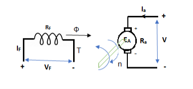
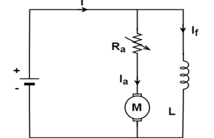
The basic circuit model for a dc machine is shown below:
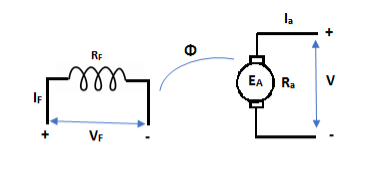
The machine operates in generating mode when the armature current is in the direction of induced emf Ea.
V = Ea – Ia Ra Ea> V
Pmech = Ea Ra = Pelect
The output power,
P0 = VIa
EaIa – VIa = Ia2 Ra
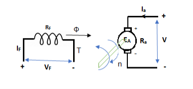
In this mode, the torque of electromagnetic origin is in opposite direction of rotation of armature.
[Pmech]gross = Shaft power = [Pmech]net + Rotational loss.
DC Motor
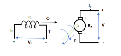
In this mode, the armature current Ia flows opposite to the emf induced i.e. Ea. The basic circuit showing this mode is below:
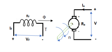
(Ea – Eb) is called as back emf here as it opposes the armature emf.
V = Ea + IaRa
Electrical power connected to mechanical form
Pelec / net = EaIa
Power input, Pi = V Ia
V Ia – EaIa = Ia2Ra = armature copper loss.
The back emf is given as
Eb = ϕ ZNP
Back EMF in DC motor
- It is seen in the generating action that when a conductor cuts the line of flux EMF gets induced in the conductor .In a DC motor after a motoring action a major start rotating and armature conductor cut the main flux so is there a generating action existing in a motor after Moni following actions
- There is induced EMF in the rotating armature conductors according to Faraday’s law of electromagnetic induction this induced EMF in the armature always act in the opposite direction to the supply voltage.
- This is according to the Lenz’s law which states that the direction of the induced EMF is always so as to oppose the cause producing it.
- In a DC motor electrical input that is the supply voltage is the cause for the armature current and the motoring action and hence this induced EMF oppose the supply voltage this EMF tries to set up a current through the our nature which is in the opposite direction to that which supply voltage is force in through the conductor.
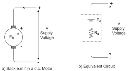
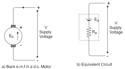
As this EMF always opposes the supply voltage it is called back EMF and denoted as Eb. Though it is denoted as Eb basically it gets generated by the generating action which we have seen earlier in case of generators. So its magnitude can be determined by the EMF equation which is derived earlier.
Eb = 
Where all symbols carry the same meaning as seen earlier in case of generators
This EMF issued systematically in figure a so if v is supply voltage in volts & Ra is the value of the armature resistance the equivalent electric circuit can be shown in figure b
Voltage equation of DC motor
From the equivalent circuit the voltage equation for a DC motor can be obtained as
V = Eb + IaRa + Brush drop
The brush drop is practically neglected.
Hence the armature current Ia is expressed as
Ia = 
Significance of back EMF
Due to the presence of back EMF the DC motor becomes a regulating machine that is motor adjust itself to draw the armature current just enough to satisfy the load demand.
The basic principle of this fact is that the back EMF is proportional to speed Eb ∝ N
When load is suddenly put on the motor. Motor tries to slow down. So speed of the motor reduces due to which back EMF also decreases. So the net voltage across the armature (V – Eb) Increases and motor draws more armature current.
Due to the increased armature current force experienced by the conductors and hence the torque on the armature increases. The increase in the torque is just sufficient to satisfy increase load demand.
When load on the motor is decreased the speed of the motor tries to increase. Hence back EMF increases. This (V-Eb)to reduce which eventually reduces the current drawn by the armature. The motor speed stops increasing when the armature current is just enough to produce the less torque required by the new load.
So back EMF regulate the flow of armature current and it automatically alters the armature current to meet the load requirement. This is the practical significance of the back EMF.
Head start the speed N of the motor is zero hence the back EMF is also zero.
1) A 220 volt DC motor has an armature resistance of 0.75 ohm. It is drawing and armature current of 30 A, driving a certain load. Calculate the induced EMF in the motor under this condition.
V=200V Ia = 30ARa = 0.75 Ω
Are the given values
For a motor,
V= Eb + IaRa
220=Eb +30*0.75
Eb =197.5 V
This is the induced EMF called a back EMF in a motor
2) Find the useful flux per pole on no load of a 250V 6 pole shunt motor having two circuit connected armature winding with 225 conductors.at normal working temperature the overall armature resistance including brushes is 0.2 ohm. The armature current is 13.3A at the no load speed of 908 RPM.
Solution
V=250 P=6 Z=220 A=2
As two circuit armature
Ra = 0.2ΩIa = 13.3 A
N=908 r.p.m
For a DC shunt motor
V = Eb + IaRa
250= Eb+13.3*0.2 i.e.Eb = 247.3 V
Back emf Eb is given by
Eb = 
247.34 = 
ϕ = 24.76mWB
Power equation of a DC motor
The voltage equation of a DC motor is given by
V = Eb + IaRa
Multiplying both sides of the above equation by Ia
V Ia = EbIa + Ia2Ra
This equation is called as power equation of a DC motor
VIa =net electric power input to the armature measured in watts
Ia2Ra=power loss due to the resistance of the armature called armature copper loss.
So difference between VIa and Ia2Ra is input losses gives the o/p of the armature.
So EbIa is called electric equivalent of gross mechanical power developed by the armature.
This is denoted as Pm
Therefore I/P to the armature-armature copper loss = gross mechanical power developed in the armature

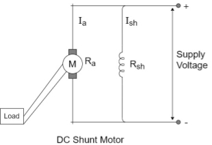
DC shunt motor
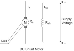
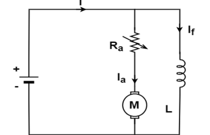
In this type the field winding is connected across the supply as shown in figure
Let Rshbe the resistance of shunt field winding and Rabe the resistance of armature winding.
The value of Ra is very small while Rshis quite large. Hence shunt field winding has more number of turns with less cross sectional area.
Torque Equation
Average conductor force
Fav = Bav l Ic
Bav = avg. Flux density over pole.
l = active conductor length.
Force, F = ZFav = BavlIcZ
T = f.r
T = Bav l IC Zr
r = mean of r gap radius.
Flux/pole ϕ = Bav τ Pl
τp = pole – pitch = 
ϕ = Bav( l
l
Bav = 
T = Bav ICl Zr = 
T = 
T = kϕIa(N-m)
The torque is uniform for given flux/pole and armature current.
Key takeaway
The EMF equation is
Ea = 
The torque is given as
T =  Nm
Nm
Types
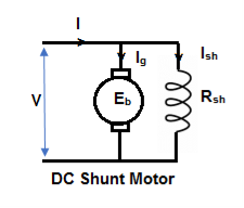
1) Shunt motor – In this, the field winding is connected in parallel with the armature.
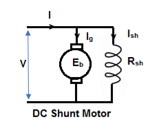
The input current I = Ia + Ish
For field winding, V = IshRsh
For armature, V = Eb + IaRa
Ia = armature current
Ish = shunt field current
V = input voltage
I = Input current
Power Input = Mechanical power + losses in armature + losses in field
VI = Pmech + Ia2Ra + Ish2Rsh
Pmech = VI – VIsh - = Ia2Ra
= V(I – Ish) – Ia2Ra
= VIa - = Ia2Rsh = (V – IaRa)Ia
Pmech = EaIa
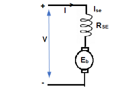
2) Series motor – In this, the field winding is connected in series with the armature.
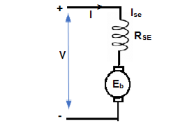
Ise = series field current
I = Ia = Ise
V = Ea + I(Ra + Rse)
VI = EaI + I2(Ra + Rse)
VI = Pmech + I2 Ra + I2Rse
Pmech = Ea I
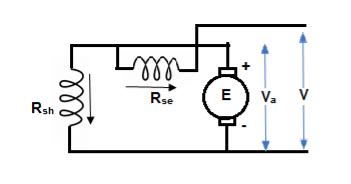
3) Compound Motor – It is a type of dc motor which had both shunt and series field windings.
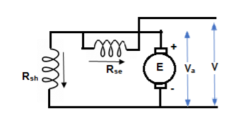
V = Ea ± Ia (Ra + Rse)
IL = Ia ± IF
They are basically of 2 types- long shunt and short shunt.
The main applications of the three types of direct current motors are given below.
Series Motors
The series DC motors are used where high starting torque is required, and variations in speed are possible. For example – the series motors are used in Traction system, Cranes, air compressors, Vacuum Cleaner, Sewing machine, etc.
Shunt Motors
The shunt motors are used where constant speed is required and starting conditions are not severe. The various applications of DC shunt motor are in Lathe Machines, Centrifugal Pumps, Fans, Blowers, Conveyors, Lifts, Weaving Machine, Spinning machines, etc.
Compound Motors
The compound motors are used where higher starting torque and fairly constant speed is required. The examples of usage of compound motors are in Presses, Shears, Conveyors, Elevators, Rolling Mills, Heavy Planners, etc.
The small DC machines whose ratings are in fractional kilowatt are mainly used as control device such in Techno generators for speed sensing and in Servo motors for positioning and tracking.
Q1) A 4 pole lap wound dc shunt generator has a useful flux per pole of 0.05 Wb. The armature winding consists of 200 turns each of 0.06 u ohm resistance. Calculate the terminal voltage when running at 900 rpm with armature current of 50 A.
Soln. Terminal voltage V =Ea – Ia Ra
Ia Ra = 50×Ra.
Ea = 
Z = 200×2=400 (each turn has two sides).
N = 900 rpm ϕ = 0.05 Wb P = A = 4
Ea =  = 300 V
Total resistance of 200 turns = 200 × 0.004 = 0.8 ohm
As there are 4 parallel paths, so resistance of each path = 0.8/4 = 0.2 ohm
There are 4 resistances in parallel of each of 0.2 ohm
Ra = 0.2/4 = 0.05 ohm
Ia Ra = 50×0.05 = 25 V
V = Ea – Ia Ra = 300 – 25 = 275 V
Q.2 A 220 V 4 pole wave wound dc series motor has 780 conductor on its armature. It has armature and series field resistance of 0.75 ohm. The motor takes a current of 30A. Find the speed and gross torque developed if flux/pole is 20 mWb?
Soln. Back emf, Eb = 
Eb = V – IaRa = 220 – (30×0.75) = 197.5 V
197.5 = 20 × 10-3 ×780×N×0.75
N = 16.88 ≈ 17
Ta = 
= 
Ta = 158.97 Nm.
Characteristics
DC Series
a) Torque and Armature current characteristics: As we have already seen that armature torque Ta is proportional to the product of flux linked and the armature current
Taαφ Ia
Since φα Ia
Ta= I2a
As Ta is proportional to the square of armature current, the curve is Parabolic as shown below.
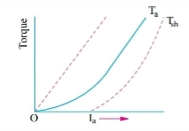
Fig: T v/s Ia characteristics
b) Speed and armature current characteristics: As we know speed (N) is related to back emf as
N α Eb/φ
But φα Ia .
So, as the value of Ia increases the vale corresponding value of φ also increases. So, N αEb/ Ia
As the speed increases the value of current decreases (inversely proportional). For various values of load current there is very small change in the value of Eb, hence can be neglected here. The curve is shown below.
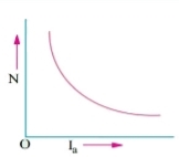
Fig: Speed verses Armature current characteristics
c) Speed and Torque characteristics: As Taαφ Ia and φα Ia , but N αEb/ Ia .So it can be easily concluded that speed and torque are inversely proportional. Hence when speed is high torque is low and vice versa. The curve is shown below.
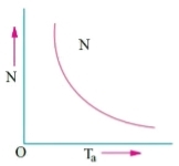
Fig: Speed verses Torque characteristics
DC Shunt
a) Torque and Armature current characteristics: As relation between torque and armature current is Taαφ Ia , assuming φ to be practically constant. So, Taα Ia and the characteristics are linear as shown below.
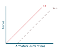
Fig: Torque versus Armature current
b) Speed and Armature current characteristics: N α Eb/φ , for φ to be practically constant N α Eb . But both Eb and φ decrease with increasing load. The drop varies from 5 to 15% of full load speed. As Eb decreases more than φ speed decreases.
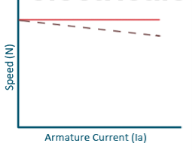
Fig: Speed verses Armature current characteristics
c) Speed and Torque Characteristics: From above to characteristics, curve for this shown below.
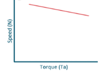
Fig: Speed verses Torque characteristics
Examples
Que) A 250V shunt motor on no load runs at 900rpm and takes 4amperes, armature and shunt field resistances are 0.2 and 250 ohms respectively. Calculate the speed when loaded taking current of 50A. The armature reactions weakens the field by 3%?
Sol: Ish=250/250=1A
Ia1=4-1=3A
Ia2=50-1=49A
Eb1=250-3*0.4=248.8V
Eb2=250-49*0.2=240.2A

ϕ2 is 3 % weaker than ϕ1
N2=898rpm
Que) The speed of a 37.3kW series motor working on 500V supply is 600 rpm at full load and 90% efficiency. If the load torque is made 250 N-m and a 5ohm resistance is connected in series with the machine, calculate the speed at which the machine will run. Assume armature and field resistance of 0.5ohm?
Sol: Load torque in first case T1=37300/2π(600/60)=593.65 N-m
Input current Ia1=37300/0.9*500=82.9A
T2=250 N-m. So, finding Ia2
For series motor T αφ Ia α Ia2
T1α  and T2α

 =82.9*
 =53.79A
Eb1=500-(82.9*0.5)=458.5V
Eb2=500-53.79(5+0.5)=204.11V


D.C Motors
- Separately Excitation
It is the curve which relates the field current and armature terminal voltage on open circuit. For generating mode, we already know that generated emf is directly proportional to flux per pole and speed of armature.
Ea ∝ ϕn
The circuit is given below-
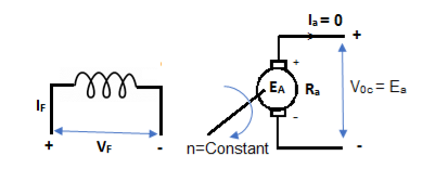
Fig: Separately Excited DC Motor
From above figure,
Voc = Ea
The magnetization characteristic of dc machines is determined by measuring Voc at rated armature speed and gradually increasing If from zero till Voc reaches above rated value of machine.
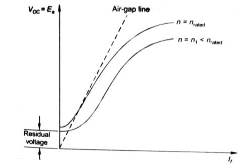
Fig: Speed current characteristic curve
From above curve, we can conclude
1) A small residue voltage is present when field is unexcited.
2) The field current If increases from initial value, the flux and hence generated emf is increased.
3) The air-gap line is the magnetic behaviour of machines air-gap. The iron being unsaturated in this region consumes negligible power.
4) The open circuit cost is conducted by exciting the main field winding.
5) The equivalent main field current is given
If(eq) = If ± 
Nf, main field turns
If, main field current
Nse, main series turn
Ise, main series current
As induced emf is reduced by demagnetizing effect of armature reaction in saturation region of curve. So, the modified magnetization characteristics are shown below with Ia = 0, Ia = Ia1, Ia = Ia2.
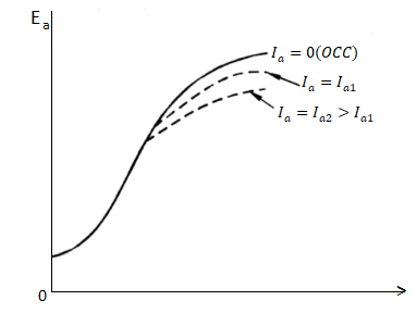
Fig: Armature reaction in Speed current characteristics
B. Self excitation
The magnetization curve relates the no load voltage to the field current. The circuit is shown below
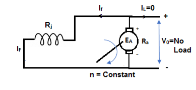
Fig: Self Excited DC motor
The field is introduced after the armature has been brought to rated speed. Just the moment after switching on the field, residue armature voltage exists which causes small value of field current. A fine steady state value is attained because of the saturation state of machines magnetic circuit. The magnetization curve is shown below:
The current in armature can be related to field current as
Ia = If
V = Ea- If Ra
In this case, field current is very small, so
V ≈ Ea (If) [magnetization characteristic]
For field current,
V = If Rf
- The intersection point P on Rf line gives the values of no-load voltage Vo and corresponding field current If.
- Vo can be adjusted by varying Rf.
- Further, the above plot can be assessed by keeping armature speed constant and varying Rf. The plot is shown below.
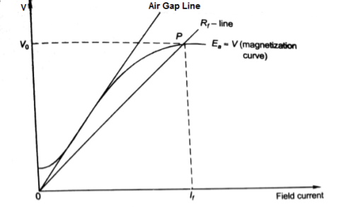
Fig: Magnetising Curve
- As Rf is increased, the value of Vo decreases.
- Value of Vo is not defined for (Rf3 = Rfc).
- As the value of field resistance here is increased to high value but does not produce high Vo, rather its value is close to residue voltage. Hence, machine field fails to excite and this value of resistance is called critical resistance Rc.
- Now keeping Rf fixed and varying armature speed, the plot is shown below:
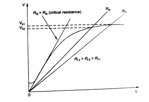
Fig: Characteristic curve with Rf fixed
- As the speed decreases, the open circuit characteristics also decrease proportionally.
- At critical Speed, the generator fails to excite.
Speed control of D.C Motors, Field Control
The speed control of DC motor is given by
N = 
The speed can be controlled by varying
i)Φ=flux/pole
Ii)Ra=Armature resistance
Iii)V=Applied voltage
For DC Series Motor: In DC Series motor speed control can be done in two ways:
i)Flux Control: In this there are four ways to control speed
a) Field Divertors
b) Armature Divertors
c) Trapped Field control field
d)Paralleling field coils
Ii) Variable resistance in series with motor
Firstly, discussing the Flux Control method to control speed in DC Series motor.
a) Field Divertors: In this one variable resistance in parallel to the field winding is connected. It is called as field divertor. We can control the current through the field divertor by adjusting its resistance. As we can control the current, the flux can also be decreased and hence the speed will increase. Below shows the figure.
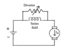
Fig: Field Divertor
b) Armature Divertor: In this the variation in speed can be controlled by varying the divertor resistance. As we know TaαφIa and Nαl/∅. Hence if flux increases (as Ia can be reduced due to armature divertor) speed will decrease. The figure is shown below.
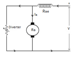
Fig: Armature Divertor
c)Trapped Field control field: In this the series field turns can be changed according to our wish. The speed can be increased by removing off some of the series turns. The figure is shown below.
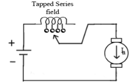
Fig: Trapped Field control field
d) Paralleling field coils: In this speed control can be done by regrouping the field coils.
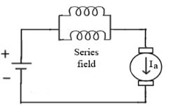
Fig: Paralleling of field coils
Ii) Variable resistance in series with motor: The voltage across armature can be reduced increasing the resistance in series with it. As the voltage reduces the speed also reduces. The below fig a shows the variable resistance across armature and fig b shows the variation of speed with respect to armature current.
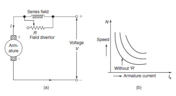
Fig: Circuit and characteristics of variable resistance in series with motor
For DC Shunt Motor: There are three basic methods to control the speed of DC Shunt motor listed below
i)Flux control method
Ii)Armature or Rheostatic control
Iii)Voltage control
i) Flux control method: As we already know that flux and speed for shunt motors are inversely proportional to each other. As the name suggests flux control which means we can control the flux and maintain required speed. The flux can be controlled by changing Ish with help of shunt field rheostat. The figure is shown below.
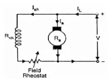
Fig: Flux control method
Ii) Armature or Rheostatic control: This is the most common method employed. In this the controlling resistance is connected directly in series with the supply of the motor. As resistance Ra is increased potential drop across armature decreases, and hence the speed too decreases. The figure is shown below.
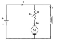
Fig: Armature control
One more to control speed here is shunting the armature and a rheostat in series with the armature is involved in this method of speed control. The voltage applied to the armature varies by varying series rheostat R1. The exciting current can be varied by varying the armature shunting resistance R2. This method of speed control is not economical due to considerable power losses in speed controlling resistances.
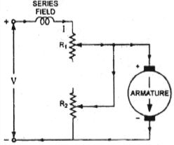
Fig: shunted armature speed control
Iii) Voltage control method: There are two ways in voltage control method
a) Multiple voltage control: In this method the shunt field of motor is connected permanently to a fixed exciting voltage, but armature is supplied with different voltages. The armature speed is approximately proportional to these different voltages. This method is not used now.
b) Ward-Leonard System: The figure below shows the ward-Leonard system. In this method speed of motor M1is controlled which is powered by generator G. The shunt field of motor is connected across DC supply. The motor M2 derives the generator. When the output voltage of the generator is fed to the motor M1 then the motor starts to rotate. When the output voltage of the generator varies then the speed of the motor also varies. By controlling the output voltage of generator speed of motor can be controlled. To attain this a field regulator is connected across the generator. The direction of rotation of motor can be reversed by excitation current of generator, this will happen by reversing the switch R.S. The motor-generator should run in same direction.
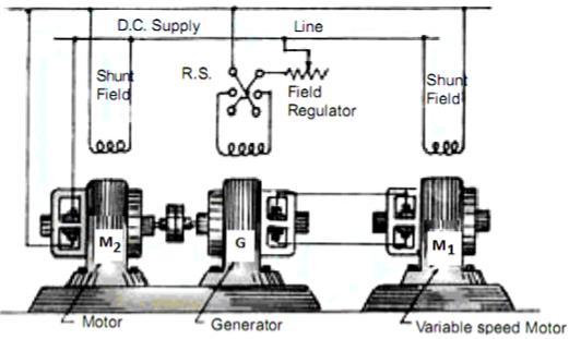
Fig: Ward Leonard System
Key takeaway
The speed can be controlled by varying
i)Φ=flux/pole
Ii)Ra=Armature resistance
Iii)V=Applied voltage
Que) A dc series motor drives a load torque of which varies as the square of the speed. The motor takes a current of 15A when speed is 500 rpm. Calculate the speed and the current when the motor field winding is shunted by a diverter of same resistance as that of the field winding.
Sol: As we already know TaαφIa and Nα l/∅
Ta1αN12
Ta2α N22

Ta1 αφ1Ia1
Ta2 αφ2Ia2
As field current is half the armature current so 
 ………(1)

Neglecting armature and series winding drop.
 ………(2)
From 1 and 2


152=25.2A
From 2 we get N2=500*2*15/25.2=595.2 rpm
Que) A 200V dc shunt motor running at 900rpm takes an armature current of 15.5A. It is required to reduce the speed to 600 rpm. What must be the value of resistance to be inserted in the armature circuit if the original resistance is0.4Ω?
Sol: N1=900rpm
Eb1=200-15.5*0.4=193.8 V
N2=600rpm
Eb2=200-15.5*Rt
Rt= total armature circuit resistance
Assuming armature current constant. Φ1= Φ2

Rt=4.57 Ω
Additional resistance required=Rt-Ra=4.57-0.4=4.17 Ω
Losses
1) Copper loss –
Armature Cu loss = Ia2 Ra
Field Cu loss: a) For shunt = Ish2Rsh
b) For series = Ise2Rse
2) Magnetic loss
a) Hysteresis loss: Wh B1.6max f
b) Eddy current loss: We B2max f2
3) Mechanical loss – They are basically the frictional losses at bearings and commutators.
Efficiency-
1) Mechanical Efficiency


2) Electrical efficiency

3) Overall efficiency


Necessity of Starter
All motors should be started with external resistance in armature circuit to limit the starting current to safe values, if not then there can be a risk of high value of torque which can cause mechanical shock to the shaft and it can also cause heavy sparking at the brushes which can damage the commutator and brush gear. At the time of starting the induced emf of motor is zero. In case of direct start of motor, the toque is much higher and motor starts quickly, which saves the energy and reduces temperature rise. Maximum allowable starting current cannot be more than 1.5 to 2.0 times the rated value. For variable speed the starting of motor has no problem.
The connection diagram of DC Shunt motor starter is shown below. It is the manual starter.
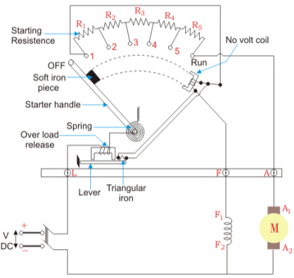
Fig: DC Shunt motor starter
In shunt motor starting to maintain high torque the starting resistance is arranged in steps. When starter is in ON position the starting resistance is cut out. The handle can go back to OFF position when there is no field current and in case of overload when the contact of relay at armature current is above certain value. Modern industries use push button type automatic starters. As shown in the figure below
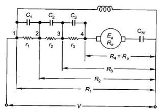
Fig: Shunt motor starting
They have automatic relays that short the section of starting resistors when the armature current has dropped to a pre-set value.
Calculation of starter step for DC Shunt Motor
From above figure when the stud is moved to point 1, the current I1 is reached.
I1 = V/R1
When the speed of motor increases the current decreases and the back emf rises. The value of current I2 is given as
I2=
 is back emf. The current I1 is given as
I1=

For k stud starter


Hence

After calculating starter step
i)Find R1
Ii)Find number of steps k
Iii)Find R1, R2…….
Key takeaway
At the time of starting the induced emf of motor is zero. In case of direct start of motor, the toque is much higher and motor starts quickly, which saves the energy and reduces temperature rise.
Que) A starter required for a 220V shunt motor. The maximum allowable current is 45A and the maximum current is about 35A. Find the number of sections of starter resistance required and the resistance of each section. The armature resistance of motor is 0.4 ohm?
Sol: I1=45 A , I2=35 A
 =1.28
=1.28
R1= Ω
Ω
As 
 =
= =11.1
=11.1


As we already know 
R1=4.44Ω
R2=
R3=
r1= R1- R2=2.01
r2= R2- R3=1.1
Similarly, r3=0.60 , r4=0.20
 can be calculated.
Three- point starter DC shunt motor
A 3- point starter is a device that helps in the starting and running of a DC shunt motor or compound wound DC motor.
A starter is a variable resistance, integrated into the number of sections as shown in the figure.
The contact points of these sections are called studs and are shown separately as OFF, 1, 2, 3, 4, 5, RUN.
There are three main points, referred to as
- ‘L’ Line terminal (Connected to positive of supply)
- ‘A’ Armature terminal (Connected to the armature winding)
- ‘F’ Field terminal (Connected to the field winding)
The construction of 3 point starter reveals that the point ‘L’ is connected to an electromagnet called overload release (OLR) as shown in the figure.
The other end of OLR is connected to the lower end of conducting lever of starter handle where spring is also attached with it, and the starter handle also contains a soft iron piece housed on it.
This handle is free to move to the other side RUN against the force of the spring. This spring brings back the handle to its original OFF position under the influence of its own force.
Another parallel path is derived from the stud ‘1’, given to another electromagnet called No Volt Coil (NVC) which is further connected to terminal ‘F.’ The starting resistance at starting is entirely in series with the armature. The OLR and NVC act as the two protecting devices of the starter.
Working of Three Point Starter
The working of the 3 point starter. To start with the handle is in the OFF position when the supply to the DC motor is switched on. Then handle is slowly moved against the spring force to contact stud No. 1.
At this point, field winding of the shunt or the compound motor gets supply through the parallel path provided to starting the resistance, through No Voltage Coil.
While entire starting resistance comes in series with the armature. The high starting armature current thus gets limited as the current equation at this stage becomes:
Ia = E / (Ra + Rst)
As the handle is moved further, it goes on making contact with studs 2, 3, 4, etc., thus gradually cutting off the series resistance from the armature circuit as the motor gathers speed.
Finally, when the starter handle is in ‘RUN’ position, the entire starting resistance is eliminated, and the motor runs with normal speed.This is because back emf is developed consequently with speed to counter the supply voltage and reduce the armature current.
So, the external electrical resistance is not required anymore and is removed for optimum operation. The handle is moved manually from OFF to the RUN position with the development of speed.
Four -point starter:
A 4 -point starter protects the armature of a DC shunt motor or compound wound DC motor against the initially high starting current of the DC motor.
A 4- point starter as the name suggests has 4 main operational points, namely
‘L’ Line terminal (Connected to positive of supply.)
‘A’ Armature terminal (Connected to the armature winding.)
‘F’ Field terminal. (Connected to the field winding.)
Like in the case of the 3 -point starter, and in addition to it there is,
A 4th point N (Connected to the No Voltage Coil NVC)
The difference in case of a 4 point starter is that the No Voltage Coil is connected independently across the supply through the fourth terminal called ‘N’ in addition to the ‘L’, ‘F’ and ‘A’.
As a direct consequence of that, any change in the field supply current does not bring about any difference in the performance of the NVC. Thus, it must be ensured that no voltage coil always produce a force which is strong enough to hold the handle in its ‘RUN’ position, against the force of the spring, under all the operational conditions.
Such a current is adjusted through No Voltage Coil with the help of fixed resistance R connected in series with the NVC using fourth point ‘N’ as shown in the figure above.
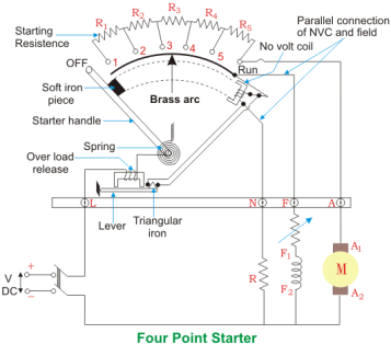
Fig. 4 Point Starter Diagram
The 4 point and 3 point starters are similar in all other ways like possessing is a variable resistance, integrated into number of sections as shown in the figure above.
The contact points of these sections are called studs and are shown separately as OFF, 1, 2, 3, 4, 5, RUN, over which the handle is free to be maneuvered manually to regulate the starting current with gathering speed.
Considering that supply is given and the handle is taken stud No.1, then the circuit is complete and the line current that starts flowing through the starter.
In this situation the current will be divided into 3 parts, flowing through 3 different points.
1 part flows through the starting resistance (R1+ R2 + R3…..) and then to the armature.
A 2nd part flowing through the field winding F.
And a 3rd part flowing through the no voltage coil in series with the protective resistance R.
So, the point to be noted here is that with this particular arrangement any change in the shunt field circuit does not bring about any change in the no voltage coil as the two circuits are independent of each other.
This essentially means that the electromagnet pull subjected upon the soft iron bar of the handle by the no voltage coil at all points of time should be high enough to keep the handle at its RUN position, or rather prevent the spring force from restoring the handle at its original OFF position, irrespective of how the field rheostat is adjusted.
Armature Reactions
When armature of a DC Machine carries current, the distributed armature winding produces its own mmf which is known as armature reaction. The figure is shown below.
The nature of armature reaction in a DC machine is cross magnetizing with its axis along the (90° to main pole).
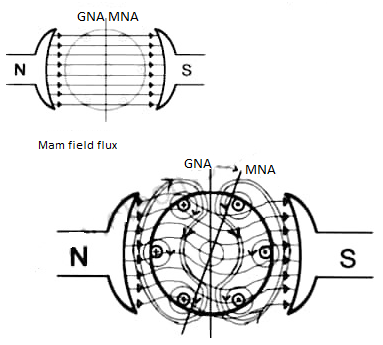
Fig MNA and GNA
MNA (Magnetic Neutral Axis) It is the axis along which no EMF generated in the armature conductors.
GNA (Geometrical Neutral Axis) It is perpendicular to the field axis.
When DC machine is running the flux due to armature and field winding exists. The armature flux is dominant on the later and hence disturbing the main field flux. This effect is called armature reaction in DC machines.
Example
Q. 1 A 4 pole, 210 V shunt motor has 450 lap wound conductor. It takes 32 A from supply mains and develops output power of 4.5 kW. The field takes 1 A. The armature resistance is 0.09 ohm and flux per pole is 30 mWb. Calculate speed and torque.
Soln. Ia = 32-1 = 31 n
Eb = V – Ia Ra = 210 - (0.09×31) = 207.21 V
Eb =
207.21 = 
N = 920.9 rpm
Tsh = 

Q.2 A 220 V, dc shunt motor has an armature resistance of 0.3 ohm and field resistance of 105 ohm. At no load speed is 1200 rpm and armature current is 2.3 A on application of rated load speed drops to 1120 rpm. Find the current and power input when motor delivers rated load.
Soln. N1 = 1200 rpm Eb1 = 220 – (0.3×2.3) = 219.31 V
N2 = 1120 rpm Eb2 = 220 – 0.3 Ia2


Ia2 = 37.93 A
Line current = Ia2 + Ish = 37.93 + (220/105) = 40 A
Power input = 220 × 40 = 8800 W
Q.3 A 230 V shunt motor runs at 1000 rpm at no load and takes 6A. The total armature resistance is 0.2 ohm and field resistance is 210 ohms. Calculate the speed when loaded and taking 40 A. Assume flux constant.
Soln.


Eb0 = V – Ia0Ra = 230 – (5×0.2) = 229 V
Eb = 230 – (39 × 0.2) = 222.2 V

N = 970.3 rpm
Q.4 The armature resistance of a 15 kW, 230 V series motor is 0? 1 ohm, the brush voltage drop is 3 V and series field resistance is 0.05 ohm. The motor takes 60 A speed is 600 rpm. Calculate speed when current is 100 A.
Soln.
Eb1 = 230 – (0.1 + 0.05) = 221 V
Eb = 230 – (0.1 + 0.05)100 = 215 V
ϕ ∝ Ia
Φ1∝60
Φ2∝100


N2=350.22 rpm
Q.5 A 230V DC Shunt motor takes 4A at no load when running at 600 rpm. The field resistance is 100 ohms. The resistance of armature at standstill gives a drop of 6V across armature terminals when 10A were passed through it. Find i) Speed at no load (ii) Torque. Normal input of motor is 6kW
Sol:
i)Speed

Ish=  =2.3A
=2.3A
F.L Power=6000
F.L line current=  =26.08A
Ia=26.08-2.3=23.78A
Ra= =0.6Ω
=0.6Ω
Eb = 230 – ( 2.3 × 0.6) = 228.62 V

N=566.2 rpm
Ii)Torque
Ta = 
Ta = 86.53 Nm
The main applications of the three types of direct current motors are given below.
Series Motors
The series DC motors are used where high starting torque is required, and variations in speed are possible. For example – the series motors are used in Traction system, Cranes, air compressors, Vacuum Cleaner, Sewing machine, etc.
Shunt Motors
The shunt motors are used where constant speed is required and starting conditions are not severe. The various applications of DC shunt motor are in Lathe Machines, Centrifugal Pumps, Fans, Blowers, Conveyors, Lifts, Weaving Machine, Spinning machines, etc.
Compound Motors
The compound motors are used where higher starting torque and fairly constant speed is required. The examples of usage of compound motors are in Presses, Shears, Conveyors, Elevators, Rolling Mills, Heavy Planners, etc.
The small DC machines whose ratings are in fractional kilowatt are mainly used as control device such in Techno generators for speed sensing and in Servo motors for positioning and tracking.
References
1. I. J. Nagrath, D.P. Kothari, “Electrical Machines,”, Tata McGraw- Hill Publishing
Company Ltd.
2. P.S. Bhimbra,”Electrical Machinery”, Khanna Publishers.
3. P.K. Mukherjee, S. Chakrabvorty, “Electrical Machines”, Dhanpat Rai Publications.
4. P.S. Bhimbra, “Generalized Theory in Electrical Machines”, Khanna Publishers.
5. D C Kulshreshtha, “Basic Electrical Engineering,” The McGraw Hill Higher Education Private Limited, New Delhi.
Unit - 2
D.C. Machines
DC Generator
The basic circuit model for a dc machine is shown below:
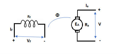
The machine operates in generating mode when the armature current is in the direction of induced emf Ea.
V = Ea – Ia Ra Ea> V
Pmech = Ea Ra = Pelect
The output power,
P0 = VIa
EaIa – VIa = Ia2 Ra
In this mode, the torque of electromagnetic origin is in opposite direction of rotation of armature.
[Pmech]gross = Shaft power = [Pmech]net + Rotational loss.
DC Motor
In this mode, the armature current Ia flows opposite to the emf induced i.e. Ea. The basic circuit showing this mode is below:
(Ea – Eb) is called as back emf here as it opposes the armature emf.
V = Ea + IaRa
Electrical power connected to mechanical form
Pelec / net = EaIa
Power input, Pi = V Ia
V Ia – EaIa = Ia2Ra = armature copper loss.
The back emf is given as
Eb = ϕ ZNP
Back EMF in DC motor
- It is seen in the generating action that when a conductor cuts the line of flux EMF gets induced in the conductor .In a DC motor after a motoring action a major start rotating and armature conductor cut the main flux so is there a generating action existing in a motor after Moni following actions
- There is induced EMF in the rotating armature conductors according to Faraday’s law of electromagnetic induction this induced EMF in the armature always act in the opposite direction to the supply voltage.
- This is according to the Lenz’s law which states that the direction of the induced EMF is always so as to oppose the cause producing it.
- In a DC motor electrical input that is the supply voltage is the cause for the armature current and the motoring action and hence this induced EMF oppose the supply voltage this EMF tries to set up a current through the our nature which is in the opposite direction to that which supply voltage is force in through the conductor.
As this EMF always opposes the supply voltage it is called back EMF and denoted as Eb. Though it is denoted as Eb basically it gets generated by the generating action which we have seen earlier in case of generators. So its magnitude can be determined by the EMF equation which is derived earlier.
Eb = 
Where all symbols carry the same meaning as seen earlier in case of generators
This EMF issued systematically in figure a so if v is supply voltage in volts & Ra is the value of the armature resistance the equivalent electric circuit can be shown in figure b
Voltage equation of DC motor
From the equivalent circuit the voltage equation for a DC motor can be obtained as
V = Eb + IaRa + Brush drop
The brush drop is practically neglected.
Hence the armature current Ia is expressed as
Ia = 
Significance of back EMF
Due to the presence of back EMF the DC motor becomes a regulating machine that is motor adjust itself to draw the armature current just enough to satisfy the load demand.
The basic principle of this fact is that the back EMF is proportional to speed Eb ∝ N
When load is suddenly put on the motor. Motor tries to slow down. So speed of the motor reduces due to which back EMF also decreases. So the net voltage across the armature (V – Eb) Increases and motor draws more armature current.
Due to the increased armature current force experienced by the conductors and hence the torque on the armature increases. The increase in the torque is just sufficient to satisfy increase load demand.
When load on the motor is decreased the speed of the motor tries to increase. Hence back EMF increases. This (V-Eb)to reduce which eventually reduces the current drawn by the armature. The motor speed stops increasing when the armature current is just enough to produce the less torque required by the new load.
So back EMF regulate the flow of armature current and it automatically alters the armature current to meet the load requirement. This is the practical significance of the back EMF.
Head start the speed N of the motor is zero hence the back EMF is also zero.
1) A 220 volt DC motor has an armature resistance of 0.75 ohm. It is drawing and armature current of 30 A, driving a certain load. Calculate the induced EMF in the motor under this condition.
V=200V Ia = 30ARa = 0.75 Ω
Are the given values
For a motor,
V= Eb + IaRa
220=Eb +30*0.75
Eb =197.5 V
This is the induced EMF called a back EMF in a motor
2) Find the useful flux per pole on no load of a 250V 6 pole shunt motor having two circuit connected armature winding with 225 conductors.at normal working temperature the overall armature resistance including brushes is 0.2 ohm. The armature current is 13.3A at the no load speed of 908 RPM.
Solution
V=250 P=6 Z=220 A=2
As two circuit armature
Ra = 0.2ΩIa = 13.3 A
N=908 r.p.m
For a DC shunt motor
V = Eb + IaRa
250= Eb+13.3*0.2 i.e.Eb = 247.3 V
Back emf Eb is given by
Eb = 
247.34 = 
ϕ = 24.76mWB
Power equation of a DC motor
The voltage equation of a DC motor is given by
V = Eb + IaRa
Multiplying both sides of the above equation by Ia
V Ia = EbIa + Ia2Ra
This equation is called as power equation of a DC motor
VIa =net electric power input to the armature measured in watts
Ia2Ra=power loss due to the resistance of the armature called armature copper loss.
So difference between VIa and Ia2Ra is input losses gives the o/p of the armature.
So EbIa is called electric equivalent of gross mechanical power developed by the armature.
This is denoted as Pm
Therefore I/P to the armature-armature copper loss = gross mechanical power developed in the armature

DC shunt motor
In this type the field winding is connected across the supply as shown in figure
Let Rshbe the resistance of shunt field winding and Rabe the resistance of armature winding.
The value of Ra is very small while Rshis quite large. Hence shunt field winding has more number of turns with less cross sectional area.
Torque Equation
Average conductor force
Fav = Bav l Ic
Bav = avg. Flux density over pole.
l = active conductor length.
Force, F = ZFav = BavlIcZ
T = f.r
T = Bav l IC Zr
r = mean of r gap radius.
Flux/pole ϕ = Bav τ Pl
τp = pole – pitch = 
ϕ = Bav( l
l
Bav = 
T = Bav ICl Zr = 
T = 
T = kϕIa(N-m)
The torque is uniform for given flux/pole and armature current.
Key takeaway
The EMF equation is
Ea = 
The torque is given as
T =  Nm
Nm
Types
1) Shunt motor – In this, the field winding is connected in parallel with the armature.
The input current I = Ia + Ish
For field winding, V = IshRsh
For armature, V = Eb + IaRa
Ia = armature current
Ish = shunt field current
V = input voltage
I = Input current
Power Input = Mechanical power + losses in armature + losses in field
VI = Pmech + Ia2Ra + Ish2Rsh
Pmech = VI – VIsh - = Ia2Ra
= V(I – Ish) – Ia2Ra
= VIa - = Ia2Rsh = (V – IaRa)Ia
Pmech = EaIa
2) Series motor – In this, the field winding is connected in series with the armature.
Ise = series field current
I = Ia = Ise
V = Ea + I(Ra + Rse)
VI = EaI + I2(Ra + Rse)
VI = Pmech + I2 Ra + I2Rse
Pmech = Ea I
3) Compound Motor – It is a type of dc motor which had both shunt and series field windings.
V = Ea ± Ia (Ra + Rse)
IL = Ia ± IF
They are basically of 2 types- long shunt and short shunt.
The main applications of the three types of direct current motors are given below.
Series Motors
The series DC motors are used where high starting torque is required, and variations in speed are possible. For example – the series motors are used in Traction system, Cranes, air compressors, Vacuum Cleaner, Sewing machine, etc.
Shunt Motors
The shunt motors are used where constant speed is required and starting conditions are not severe. The various applications of DC shunt motor are in Lathe Machines, Centrifugal Pumps, Fans, Blowers, Conveyors, Lifts, Weaving Machine, Spinning machines, etc.
Compound Motors
The compound motors are used where higher starting torque and fairly constant speed is required. The examples of usage of compound motors are in Presses, Shears, Conveyors, Elevators, Rolling Mills, Heavy Planners, etc.
The small DC machines whose ratings are in fractional kilowatt are mainly used as control device such in Techno generators for speed sensing and in Servo motors for positioning and tracking.
Q1) A 4 pole lap wound dc shunt generator has a useful flux per pole of 0.05 Wb. The armature winding consists of 200 turns each of 0.06 u ohm resistance. Calculate the terminal voltage when running at 900 rpm with armature current of 50 A.
Soln. Terminal voltage V =Ea – Ia Ra
Ia Ra = 50×Ra.
Ea = 
Z = 200×2=400 (each turn has two sides).
N = 900 rpm ϕ = 0.05 Wb P = A = 4
Ea =  = 300 V
Total resistance of 200 turns = 200 × 0.004 = 0.8 ohm
As there are 4 parallel paths, so resistance of each path = 0.8/4 = 0.2 ohm
There are 4 resistances in parallel of each of 0.2 ohm
Ra = 0.2/4 = 0.05 ohm
Ia Ra = 50×0.05 = 25 V
V = Ea – Ia Ra = 300 – 25 = 275 V
Q.2 A 220 V 4 pole wave wound dc series motor has 780 conductor on its armature. It has armature and series field resistance of 0.75 ohm. The motor takes a current of 30A. Find the speed and gross torque developed if flux/pole is 20 mWb?
Soln. Back emf, Eb = 
Eb = V – IaRa = 220 – (30×0.75) = 197.5 V
197.5 = 20 × 10-3 ×780×N×0.75
N = 16.88 ≈ 17
Ta = 
= 
Ta = 158.97 Nm.
Characteristics
DC Series
a) Torque and Armature current characteristics: As we have already seen that armature torque Ta is proportional to the product of flux linked and the armature current
Taαφ Ia
Since φα Ia
Ta= I2a
As Ta is proportional to the square of armature current, the curve is Parabolic as shown below.
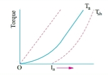
Fig: T v/s Ia characteristics
b) Speed and armature current characteristics: As we know speed (N) is related to back emf as
N α Eb/φ
But φα Ia .
So, as the value of Ia increases the vale corresponding value of φ also increases. So, N αEb/ Ia
As the speed increases the value of current decreases (inversely proportional). For various values of load current there is very small change in the value of Eb, hence can be neglected here. The curve is shown below.
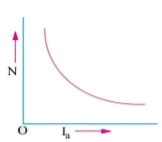
Fig: Speed verses Armature current characteristics
c) Speed and Torque characteristics: As Taαφ Ia and φα Ia , but N αEb/ Ia .So it can be easily concluded that speed and torque are inversely proportional. Hence when speed is high torque is low and vice versa. The curve is shown below.
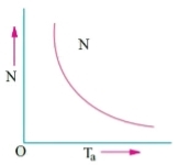
Fig: Speed verses Torque characteristics
DC Shunt
a) Torque and Armature current characteristics: As relation between torque and armature current is Taαφ Ia , assuming φ to be practically constant. So, Taα Ia and the characteristics are linear as shown below.
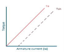
Fig: Torque versus Armature current
b) Speed and Armature current characteristics: N α Eb/φ , for φ to be practically constant N α Eb . But both Eb and φ decrease with increasing load. The drop varies from 5 to 15% of full load speed. As Eb decreases more than φ speed decreases.
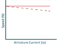
Fig: Speed verses Armature current characteristics
c) Speed and Torque Characteristics: From above to characteristics, curve for this shown below.
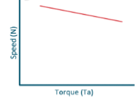
Fig: Speed verses Torque characteristics
Examples
Que) A 250V shunt motor on no load runs at 900rpm and takes 4amperes, armature and shunt field resistances are 0.2 and 250 ohms respectively. Calculate the speed when loaded taking current of 50A. The armature reactions weakens the field by 3%?
Sol: Ish=250/250=1A
Ia1=4-1=3A
Ia2=50-1=49A
Eb1=250-3*0.4=248.8V
Eb2=250-49*0.2=240.2A

ϕ2 is 3 % weaker than ϕ1
N2=898rpm
Que) The speed of a 37.3kW series motor working on 500V supply is 600 rpm at full load and 90% efficiency. If the load torque is made 250 N-m and a 5ohm resistance is connected in series with the machine, calculate the speed at which the machine will run. Assume armature and field resistance of 0.5ohm?
Sol: Load torque in first case T1=37300/2π(600/60)=593.65 N-m
Input current Ia1=37300/0.9*500=82.9A
T2=250 N-m. So, finding Ia2
For series motor T αφ Ia α Ia2
T1α  and T2α

 =82.9*
 =53.79A
Eb1=500-(82.9*0.5)=458.5V
Eb2=500-53.79(5+0.5)=204.11V


D.C Motors
- Separately Excitation
It is the curve which relates the field current and armature terminal voltage on open circuit. For generating mode, we already know that generated emf is directly proportional to flux per pole and speed of armature.
Ea ∝ ϕn
The circuit is given below-
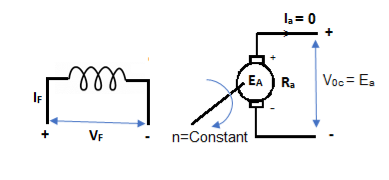
Fig: Separately Excited DC Motor
From above figure,
Voc = Ea
The magnetization characteristic of dc machines is determined by measuring Voc at rated armature speed and gradually increasing If from zero till Voc reaches above rated value of machine.
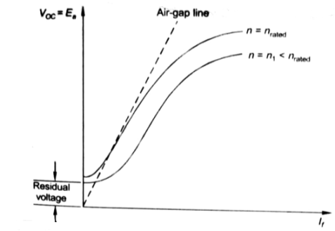
Fig: Speed current characteristic curve
From above curve, we can conclude
1) A small residue voltage is present when field is unexcited.
2) The field current If increases from initial value, the flux and hence generated emf is increased.
3) The air-gap line is the magnetic behaviour of machines air-gap. The iron being unsaturated in this region consumes negligible power.
4) The open circuit cost is conducted by exciting the main field winding.
5) The equivalent main field current is given
If(eq) = If ± 
Nf, main field turns
If, main field current
Nse, main series turn
Ise, main series current
As induced emf is reduced by demagnetizing effect of armature reaction in saturation region of curve. So, the modified magnetization characteristics are shown below with Ia = 0, Ia = Ia1, Ia = Ia2.
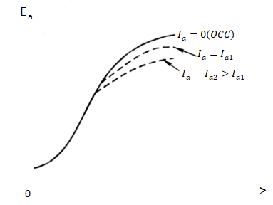
Fig: Armature reaction in Speed current characteristics
B. Self excitation
The magnetization curve relates the no load voltage to the field current. The circuit is shown below
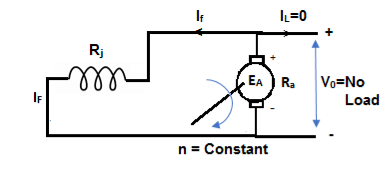
Fig: Self Excited DC motor
The field is introduced after the armature has been brought to rated speed. Just the moment after switching on the field, residue armature voltage exists which causes small value of field current. A fine steady state value is attained because of the saturation state of machines magnetic circuit. The magnetization curve is shown below:
The current in armature can be related to field current as
Ia = If
V = Ea- If Ra
In this case, field current is very small, so
V ≈ Ea (If) [magnetization characteristic]
For field current,
V = If Rf
- The intersection point P on Rf line gives the values of no-load voltage Vo and corresponding field current If.
- Vo can be adjusted by varying Rf.
- Further, the above plot can be assessed by keeping armature speed constant and varying Rf. The plot is shown below.
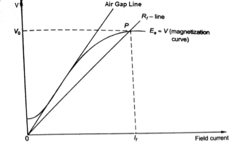
Fig: Magnetising Curve
- As Rf is increased, the value of Vo decreases.
- Value of Vo is not defined for (Rf3 = Rfc).
- As the value of field resistance here is increased to high value but does not produce high Vo, rather its value is close to residue voltage. Hence, machine field fails to excite and this value of resistance is called critical resistance Rc.
- Now keeping Rf fixed and varying armature speed, the plot is shown below:
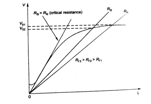
Fig: Characteristic curve with Rf fixed
- As the speed decreases, the open circuit characteristics also decrease proportionally.
- At critical Speed, the generator fails to excite.
Speed control of D.C Motors, Field Control
The speed control of DC motor is given by
N = 
The speed can be controlled by varying
i)Φ=flux/pole
Ii)Ra=Armature resistance
Iii)V=Applied voltage
For DC Series Motor: In DC Series motor speed control can be done in two ways:
i)Flux Control: In this there are four ways to control speed
a) Field Divertors
b) Armature Divertors
c) Trapped Field control field
d)Paralleling field coils
Ii) Variable resistance in series with motor
Firstly, discussing the Flux Control method to control speed in DC Series motor.
a) Field Divertors: In this one variable resistance in parallel to the field winding is connected. It is called as field divertor. We can control the current through the field divertor by adjusting its resistance. As we can control the current, the flux can also be decreased and hence the speed will increase. Below shows the figure.
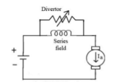
Fig: Field Divertor
b) Armature Divertor: In this the variation in speed can be controlled by varying the divertor resistance. As we know TaαφIa and Nαl/∅. Hence if flux increases (as Ia can be reduced due to armature divertor) speed will decrease. The figure is shown below.
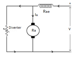
Fig: Armature Divertor
c)Trapped Field control field: In this the series field turns can be changed according to our wish. The speed can be increased by removing off some of the series turns. The figure is shown below.
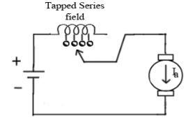
Fig: Trapped Field control field
d) Paralleling field coils: In this speed control can be done by regrouping the field coils.
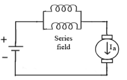
Fig: Paralleling of field coils
Ii) Variable resistance in series with motor: The voltage across armature can be reduced increasing the resistance in series with it. As the voltage reduces the speed also reduces. The below fig a shows the variable resistance across armature and fig b shows the variation of speed with respect to armature current.
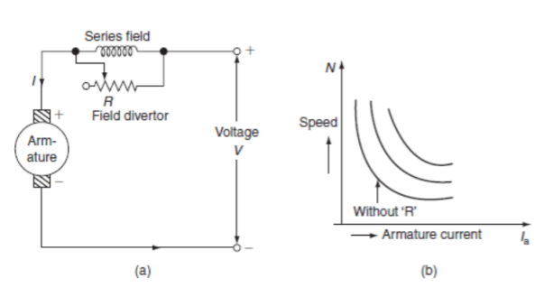
Fig: Circuit and characteristics of variable resistance in series with motor
For DC Shunt Motor: There are three basic methods to control the speed of DC Shunt motor listed below
i)Flux control method
Ii)Armature or Rheostatic control
Iii)Voltage control
i) Flux control method: As we already know that flux and speed for shunt motors are inversely proportional to each other. As the name suggests flux control which means we can control the flux and maintain required speed. The flux can be controlled by changing Ish with help of shunt field rheostat. The figure is shown below.
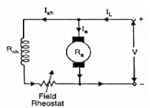
Fig: Flux control method
Ii) Armature or Rheostatic control: This is the most common method employed. In this the controlling resistance is connected directly in series with the supply of the motor. As resistance Ra is increased potential drop across armature decreases, and hence the speed too decreases. The figure is shown below.
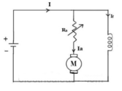
Fig: Armature control
One more to control speed here is shunting the armature and a rheostat in series with the armature is involved in this method of speed control. The voltage applied to the armature varies by varying series rheostat R1. The exciting current can be varied by varying the armature shunting resistance R2. This method of speed control is not economical due to considerable power losses in speed controlling resistances.
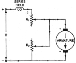
Fig: shunted armature speed control
Iii) Voltage control method: There are two ways in voltage control method
a) Multiple voltage control: In this method the shunt field of motor is connected permanently to a fixed exciting voltage, but armature is supplied with different voltages. The armature speed is approximately proportional to these different voltages. This method is not used now.
b) Ward-Leonard System: The figure below shows the ward-Leonard system. In this method speed of motor M1is controlled which is powered by generator G. The shunt field of motor is connected across DC supply. The motor M2 derives the generator. When the output voltage of the generator is fed to the motor M1 then the motor starts to rotate. When the output voltage of the generator varies then the speed of the motor also varies. By controlling the output voltage of generator speed of motor can be controlled. To attain this a field regulator is connected across the generator. The direction of rotation of motor can be reversed by excitation current of generator, this will happen by reversing the switch R.S. The motor-generator should run in same direction.
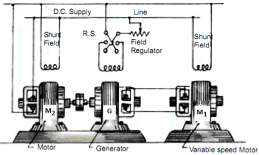
Fig: Ward Leonard System
Key takeaway
The speed can be controlled by varying
i)Φ=flux/pole
Ii)Ra=Armature resistance
Iii)V=Applied voltage
Que) A dc series motor drives a load torque of which varies as the square of the speed. The motor takes a current of 15A when speed is 500 rpm. Calculate the speed and the current when the motor field winding is shunted by a diverter of same resistance as that of the field winding.
Sol: As we already know TaαφIa and Nα l/∅
Ta1αN12
Ta2α N22

Ta1 αφ1Ia1
Ta2 αφ2Ia2
As field current is half the armature current so 
 ………(1)

Neglecting armature and series winding drop.
 ………(2)
From 1 and 2


152=25.2A
From 2 we get N2=500*2*15/25.2=595.2 rpm
Que) A 200V dc shunt motor running at 900rpm takes an armature current of 15.5A. It is required to reduce the speed to 600 rpm. What must be the value of resistance to be inserted in the armature circuit if the original resistance is0.4Ω?
Sol: N1=900rpm
Eb1=200-15.5*0.4=193.8 V
N2=600rpm
Eb2=200-15.5*Rt
Rt= total armature circuit resistance
Assuming armature current constant. Φ1= Φ2

Rt=4.57 Ω
Additional resistance required=Rt-Ra=4.57-0.4=4.17 Ω
Losses
1) Copper loss –
Armature Cu loss = Ia2 Ra
Field Cu loss: a) For shunt = Ish2Rsh
b) For series = Ise2Rse
2) Magnetic loss
a) Hysteresis loss: Wh B1.6max f
b) Eddy current loss: We B2max f2
3) Mechanical loss – They are basically the frictional losses at bearings and commutators.
Efficiency-
1) Mechanical Efficiency


2) Electrical efficiency

3) Overall efficiency


Necessity of Starter
All motors should be started with external resistance in armature circuit to limit the starting current to safe values, if not then there can be a risk of high value of torque which can cause mechanical shock to the shaft and it can also cause heavy sparking at the brushes which can damage the commutator and brush gear. At the time of starting the induced emf of motor is zero. In case of direct start of motor, the toque is much higher and motor starts quickly, which saves the energy and reduces temperature rise. Maximum allowable starting current cannot be more than 1.5 to 2.0 times the rated value. For variable speed the starting of motor has no problem.
The connection diagram of DC Shunt motor starter is shown below. It is the manual starter.
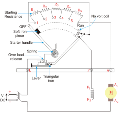
Fig: DC Shunt motor starter
In shunt motor starting to maintain high torque the starting resistance is arranged in steps. When starter is in ON position the starting resistance is cut out. The handle can go back to OFF position when there is no field current and in case of overload when the contact of relay at armature current is above certain value. Modern industries use push button type automatic starters. As shown in the figure below
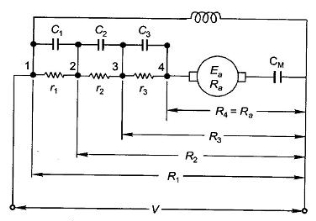
Fig: Shunt motor starting
They have automatic relays that short the section of starting resistors when the armature current has dropped to a pre-set value.
Calculation of starter step for DC Shunt Motor
From above figure when the stud is moved to point 1, the current I1 is reached.
I1 = V/R1
When the speed of motor increases the current decreases and the back emf rises. The value of current I2 is given as
I2=
 is back emf. The current I1 is given as
I1=

For k stud starter


Hence

After calculating starter step
i)Find R1
Ii)Find number of steps k
Iii)Find R1, R2…….
Key takeaway
At the time of starting the induced emf of motor is zero. In case of direct start of motor, the toque is much higher and motor starts quickly, which saves the energy and reduces temperature rise.
Que) A starter required for a 220V shunt motor. The maximum allowable current is 45A and the maximum current is about 35A. Find the number of sections of starter resistance required and the resistance of each section. The armature resistance of motor is 0.4 ohm?
Sol: I1=45 A , I2=35 A
 =1.28
=1.28
R1= Ω
Ω
As 
 =
= =11.1
=11.1


As we already know 
R1=4.44Ω
R2=
R3=
r1= R1- R2=2.01
r2= R2- R3=1.1
Similarly, r3=0.60 , r4=0.20
 can be calculated.
Three- point starter DC shunt motor
A 3- point starter is a device that helps in the starting and running of a DC shunt motor or compound wound DC motor.
A starter is a variable resistance, integrated into the number of sections as shown in the figure.
The contact points of these sections are called studs and are shown separately as OFF, 1, 2, 3, 4, 5, RUN.
There are three main points, referred to as
- ‘L’ Line terminal (Connected to positive of supply)
- ‘A’ Armature terminal (Connected to the armature winding)
- ‘F’ Field terminal (Connected to the field winding)
The construction of 3 point starter reveals that the point ‘L’ is connected to an electromagnet called overload release (OLR) as shown in the figure.
The other end of OLR is connected to the lower end of conducting lever of starter handle where spring is also attached with it, and the starter handle also contains a soft iron piece housed on it.
This handle is free to move to the other side RUN against the force of the spring. This spring brings back the handle to its original OFF position under the influence of its own force.
Another parallel path is derived from the stud ‘1’, given to another electromagnet called No Volt Coil (NVC) which is further connected to terminal ‘F.’ The starting resistance at starting is entirely in series with the armature. The OLR and NVC act as the two protecting devices of the starter.
Working of Three Point Starter
The working of the 3 point starter. To start with the handle is in the OFF position when the supply to the DC motor is switched on. Then handle is slowly moved against the spring force to contact stud No. 1.
At this point, field winding of the shunt or the compound motor gets supply through the parallel path provided to starting the resistance, through No Voltage Coil.
While entire starting resistance comes in series with the armature. The high starting armature current thus gets limited as the current equation at this stage becomes:
Ia = E / (Ra + Rst)
As the handle is moved further, it goes on making contact with studs 2, 3, 4, etc., thus gradually cutting off the series resistance from the armature circuit as the motor gathers speed.
Finally, when the starter handle is in ‘RUN’ position, the entire starting resistance is eliminated, and the motor runs with normal speed.This is because back emf is developed consequently with speed to counter the supply voltage and reduce the armature current.
So, the external electrical resistance is not required anymore and is removed for optimum operation. The handle is moved manually from OFF to the RUN position with the development of speed.
Four -point starter:
A 4 -point starter protects the armature of a DC shunt motor or compound wound DC motor against the initially high starting current of the DC motor.
A 4- point starter as the name suggests has 4 main operational points, namely
‘L’ Line terminal (Connected to positive of supply.)
‘A’ Armature terminal (Connected to the armature winding.)
‘F’ Field terminal. (Connected to the field winding.)
Like in the case of the 3 -point starter, and in addition to it there is,
A 4th point N (Connected to the No Voltage Coil NVC)
The difference in case of a 4 point starter is that the No Voltage Coil is connected independently across the supply through the fourth terminal called ‘N’ in addition to the ‘L’, ‘F’ and ‘A’.
As a direct consequence of that, any change in the field supply current does not bring about any difference in the performance of the NVC. Thus, it must be ensured that no voltage coil always produce a force which is strong enough to hold the handle in its ‘RUN’ position, against the force of the spring, under all the operational conditions.
Such a current is adjusted through No Voltage Coil with the help of fixed resistance R connected in series with the NVC using fourth point ‘N’ as shown in the figure above.
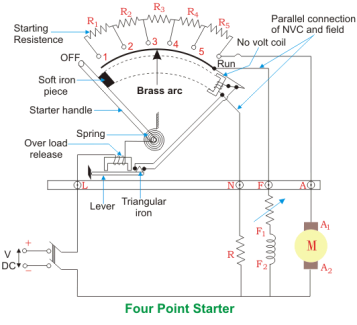
Fig. 4 Point Starter Diagram
The 4 point and 3 point starters are similar in all other ways like possessing is a variable resistance, integrated into number of sections as shown in the figure above.
The contact points of these sections are called studs and are shown separately as OFF, 1, 2, 3, 4, 5, RUN, over which the handle is free to be maneuvered manually to regulate the starting current with gathering speed.
Considering that supply is given and the handle is taken stud No.1, then the circuit is complete and the line current that starts flowing through the starter.
In this situation the current will be divided into 3 parts, flowing through 3 different points.
1 part flows through the starting resistance (R1+ R2 + R3…..) and then to the armature.
A 2nd part flowing through the field winding F.
And a 3rd part flowing through the no voltage coil in series with the protective resistance R.
So, the point to be noted here is that with this particular arrangement any change in the shunt field circuit does not bring about any change in the no voltage coil as the two circuits are independent of each other.
This essentially means that the electromagnet pull subjected upon the soft iron bar of the handle by the no voltage coil at all points of time should be high enough to keep the handle at its RUN position, or rather prevent the spring force from restoring the handle at its original OFF position, irrespective of how the field rheostat is adjusted.
Armature Reactions
When armature of a DC Machine carries current, the distributed armature winding produces its own mmf which is known as armature reaction. The figure is shown below.
The nature of armature reaction in a DC machine is cross magnetizing with its axis along the (90° to main pole).
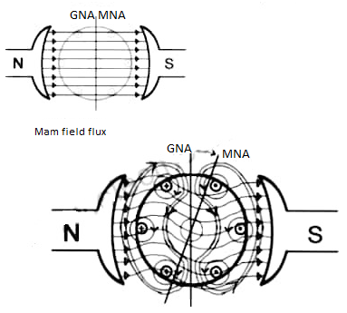
Fig MNA and GNA
MNA (Magnetic Neutral Axis) It is the axis along which no EMF generated in the armature conductors.
GNA (Geometrical Neutral Axis) It is perpendicular to the field axis.
When DC machine is running the flux due to armature and field winding exists. The armature flux is dominant on the later and hence disturbing the main field flux. This effect is called armature reaction in DC machines.
Example
Q. 1 A 4 pole, 210 V shunt motor has 450 lap wound conductor. It takes 32 A from supply mains and develops output power of 4.5 kW. The field takes 1 A. The armature resistance is 0.09 ohm and flux per pole is 30 mWb. Calculate speed and torque.
Soln. Ia = 32-1 = 31 n
Eb = V – Ia Ra = 210 - (0.09×31) = 207.21 V
Eb =
207.21 = 
N = 920.9 rpm
Tsh = 

Q.2 A 220 V, dc shunt motor has an armature resistance of 0.3 ohm and field resistance of 105 ohm. At no load speed is 1200 rpm and armature current is 2.3 A on application of rated load speed drops to 1120 rpm. Find the current and power input when motor delivers rated load.
Soln. N1 = 1200 rpm Eb1 = 220 – (0.3×2.3) = 219.31 V
N2 = 1120 rpm Eb2 = 220 – 0.3 Ia2


Ia2 = 37.93 A
Line current = Ia2 + Ish = 37.93 + (220/105) = 40 A
Power input = 220 × 40 = 8800 W
Q.3 A 230 V shunt motor runs at 1000 rpm at no load and takes 6A. The total armature resistance is 0.2 ohm and field resistance is 210 ohms. Calculate the speed when loaded and taking 40 A. Assume flux constant.
Soln.


Eb0 = V – Ia0Ra = 230 – (5×0.2) = 229 V
Eb = 230 – (39 × 0.2) = 222.2 V

N = 970.3 rpm
Q.4 The armature resistance of a 15 kW, 230 V series motor is 0? 1 ohm, the brush voltage drop is 3 V and series field resistance is 0.05 ohm. The motor takes 60 A speed is 600 rpm. Calculate speed when current is 100 A.
Soln.
Eb1 = 230 – (0.1 + 0.05) = 221 V
Eb = 230 – (0.1 + 0.05)100 = 215 V
ϕ ∝ Ia
Φ1∝60
Φ2∝100


N2=350.22 rpm
Q.5 A 230V DC Shunt motor takes 4A at no load when running at 600 rpm. The field resistance is 100 ohms. The resistance of armature at standstill gives a drop of 6V across armature terminals when 10A were passed through it. Find i) Speed at no load (ii) Torque. Normal input of motor is 6kW
Sol:
i)Speed

Ish=  =2.3A
=2.3A
F.L Power=6000
F.L line current=  =26.08A
Ia=26.08-2.3=23.78A
Ra= =0.6Ω
=0.6Ω
Eb = 230 – ( 2.3 × 0.6) = 228.62 V

N=566.2 rpm
Ii)Torque
Ta = 
Ta = 86.53 Nm
The main applications of the three types of direct current motors are given below.
Series Motors
The series DC motors are used where high starting torque is required, and variations in speed are possible. For example – the series motors are used in Traction system, Cranes, air compressors, Vacuum Cleaner, Sewing machine, etc.
Shunt Motors
The shunt motors are used where constant speed is required and starting conditions are not severe. The various applications of DC shunt motor are in Lathe Machines, Centrifugal Pumps, Fans, Blowers, Conveyors, Lifts, Weaving Machine, Spinning machines, etc.
Compound Motors
The compound motors are used where higher starting torque and fairly constant speed is required. The examples of usage of compound motors are in Presses, Shears, Conveyors, Elevators, Rolling Mills, Heavy Planners, etc.
The small DC machines whose ratings are in fractional kilowatt are mainly used as control device such in Techno generators for speed sensing and in Servo motors for positioning and tracking.
References
1. I. J. Nagrath, D.P. Kothari, “Electrical Machines,”, Tata McGraw- Hill Publishing
Company Ltd.
2. P.S. Bhimbra,”Electrical Machinery”, Khanna Publishers.
3. P.K. Mukherjee, S. Chakrabvorty, “Electrical Machines”, Dhanpat Rai Publications.
4. P.S. Bhimbra, “Generalized Theory in Electrical Machines”, Khanna Publishers.
5. D C Kulshreshtha, “Basic Electrical Engineering,” The McGraw Hill Higher Education Private Limited, New Delhi.