Unit - 3
Three Phase Induction Motor
Consider- 3Фslip ring I.M
Cut section diagram: -
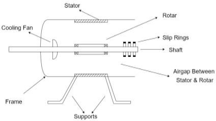
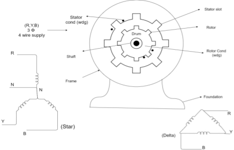
The induction motor has following important parts:
- Stator: it is the stationary part of induction motor and it is one of important part in induction motor.
- Rotor: the rotor is the rotating part of induction motor which consists of rotor wdg.
- Stator winding: this wdg. Is mounted on devastator and it generates the RMF i.e. rotating magnetic field.
- Rotor winding:- rotor winding is used to rotate the shaft of motor. This wdgis provided on rotor
- Frame :- it provides the mechanical support to the motor. It is the outer covering of motor. It protects the internal parts of motor from damage.
- Shaft:- shaft is used to connect to the load and four rotation.
- Slip rings and brushes:- slip rings are mounted on the shaft which is connected with brushes from which connection is given to the external resistant or rheostat
- Cooling fan:- this is provided for cooling purpose of motor and its internal parts.
Principle of operation of induction motor:
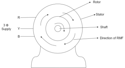
- When the 3ФA.C supply is connected across the stator of induction motor, the current starts flowing through the stator wdg. i.e the stator condition.
- Due to this current of flux (Ф) is established in the stator wdg. This flux (Ф) is alternating (changing) in nature. Thus this flux links with the rotor also, and a a Rotating Magnetic Field (RMF) is produced.
- This flux (Ф) induces in the rotor also. The RMF is produced in the air gap between stator and rotor.
- The rotor is rotating part which is till stationary, show the rotating magnetic field is cut by stationary rotor and an EMF is induced in the rotor winding. According to faraday's law of EMI the rotor EMF gives the rise to rotor current which opposes the main cause producing it according Lenz's law.
Types of induction motor:
Two main types depending upon the rotor
- Squirrel cage induction motor (squirrel cage rotor)
- Slip ring induction motor(slip ring or wound rotor)
Induction motor are also available in 1Фsupply i.e.
1. Resistance split phase induction motor
2. Capacitor start induction motor
3. Capacitor start capacitor run induction motor
4. 1Фinduction motor i.e. A.C series motors
5. Shaded pole induction motor
Torque equation of induction motor:
Torque produced in induction motor depends upon the following factors
1.The rotor power factors ( CosФ) under running condition
2.The rotor current under running condition
3. The part of RMF which induces EMF in rotor wdgi.e. flux (Ф)
We can mathematically say that,
T ∝ ϕ Ia , As per DC (M) equation
But in case of induction motor
Suffix 1 -> used for stator/stator parts (qty)
Suffix 2-> used for rotor/rotor parts(qty)
Therefore, T ∝ ϕ I2r cos ϕ2r----(1)
ϕ = flux that induces the EMF in rotor
l2r = rotor current under running condition
Cos ϕ2r = P.F of rotor
But,ϕ ∝ stator vtg E1 also i.e
ϕ ∝ E1----(2)
Transformation ratio i.e. given by K = 
Therefore,
E2 ∝ E1 and hence
E2 ∝ ϕ also
E2 at slip ’S’ is given by E2 = SE2
And also X2 at slip ‘S’ is X2 = S X2
Hence ϕ in equation can be replaced by E2
i.e. T ∝ E2 I2r cos ϕ2rU
 ----(3)----(
4 cos ϕ2r =  ------(4)
Subtract (3) and (4) into (1) equation we get,
T ∝ E2 
T ∝ 
T =  (N-m) , Torque equation of I.M.
K =  Ns’ =
Ns’ = 
T = 

At starting condition slip S=1
So, T = 

The torque developed at the moment when motor starts is called as starting torque. As we already know the motor torque Taαφ Ia. An induction motor develops gross torque Tg due to gross rotor output Pm. Then in terms of rotor input
Tg= 
In terms of rotor output the gross torque is Tg= 
Due to rotor friction and windage losses the shaft torque Tsh is less than Pm
Tsh=  (N, Ns are in rpm)
Tg =  N-m
N-m
Tsh = = 
For induction motor the torque is also proportional to the product of flux per stator pole and the rotor current, in addition to the power factor.
Starting Torque
T αφ I2 cos φ2
Or T=k φ I2 cos φ2
I2=rotor current at standstill
φ2=angle between rotor emf and rotor current
E2=rotor emf at standstill.
Also, E2αφ
So, T α E2I2 cos φ2
T=k1 E2I2 cos φ2
The starting torque Tst= k1 E2I2 cos φ2
From above section we know, I2 = Iz = E2/Z2 =  , cosφ2=R2/Z2=
  ,
,
Tst= k1 E2  .
.
For supply voltage constant, flux and E2 both are constant
Tst= 
k1=3/2πNs
Therefore, Tst=3/2πNs 
Torque-Slip Relation:
The torque slip characteristics is shown below. For low value of slip the curve is approximately a straight line. As slip increases the torque also increases and becomes maximum when s= R2/X2. This torque is called pull-out or breakdown torque Tb. From above section we already know
T= 
T α 
When slip increases more with motor load R2 becomes negligible. So, for large value of slip
T α 
Key takeaway
Tg== 
Tg  N-m
N-m
Tst= 3/2πNs 
T= = 
Starting torque and maximum torque
Starting torque is given as Tst= 
Maximum Torque Tmax =k1
Tst α
Tmax α 

a = 
Full load torque and maximum torque
Let sf be slip for full load torque.
Tfα 
Tmax α 

Dividing numerator and denominator by 

Key takeaway
Starting torque and maximum torque

Full load torque and maximum torque

Que) A 12-pole, 3-phase, 600V, 50Hz, star connected induction motor has rotor-resistance and standstill reactance of 0.04 and 0.6 ohm per phase respectively. Calculate i) speed of max. Torque ii) ratio of full load torque to max torque, if full load speed is 495rpm?
Sol: Ns=120f/P=120 x 50/12=500 rpm
For r=0.04 and x=0.6 ohm, slip torque is
Smt=a=r/x=0.04/0.6=0.067
i) Speed =(1-Smt)N=(1-0.067) x 500=466.67 rpm
Ii) Full load speed = 495rpm, slip=0.01, at full-load

Que) A 3-phase 400/200V, Y-Y connected wound rotor induction motor has 0.05 ohms resistance and 0.2 ohm stand still reactance per phase. Find the additional resistance required in the rotor circuit to make starting torque equal to the maximum torque of motor?
Sol:

Given Tst=Tmax
1=  , a=1
, a=1
a= 
1= 
r=0.15 Ω
Que: A 50hz ,6-pole induction motor has full load slip of 4%. The rotor resistance/phase = 0.02ohm and standstill reactance/phase=0.1 ohm. Find the ratio of maximum to full load torque and the speed at which the maximum torque occurs?
Sol:

a=R2/X2=0.02/0.1=0.02
 = 0.8
= 0.8
Ns = 120 x 50/6 = 1000rpm, sm= a(for maximum torque) = 0.02
N = (1-0.02) x 1000 = 980rpm
Torque of rotor in running condition is given as
T=  =
= 
Condition for maximum torque will be obtained by differentiating the above equation, we will get 


s=R2/X2
When rotor resistance per phase is equal to rotor reactance per phase under running condition, we have maximum torque. The above torque equation can be written as
Tmax = k1 
k1= 3/ 2πNs
Hence, maximum torque is given as
Tmax = 3/ 2πNs  N-m
N-m
Que) A 3-phase induction motor star connected rotor has an induced emf of 70volts between slip rings at standstill on open circuit. The rotor has a resistance and reactance per phase of 1ohm and 5ohm respectively. Calculate current/phase and power factor when slip rings are short circuited?
Sol: Standstill emf/rotor phase=70/√3 = 40.4 V
Rotor impedance/phase= √(12 + 52 = 5.09 ohm
Rotor current/phase=40.4/5.09=7.92A
Power factor cosφ=0.99
Que) A 3-phase induction motor star connected rotor has an induced emf of 70volts between slip rings at standstill on open circuit. The rotor has a resistance and reactance per phase of 1ohm and 5ohm respectively. Calculate current/phase and power factor when slip rings are connected to star connected rheostat of 2ohm?
Sol: Rotor resistance/phase=2+1 = 3 ohm
Rotor impedance/phase = √(32+52)= 5.83 ohm
Rotor current/phase = (70/√3 )/5.83 = 6.93A
Cosφ=3/5.83=0.514
Que) A 6-pole, 3-phase induction motor operates from a supply whose frequency is 50Hz. Calculate i) speed at which the magnetic field of stator is rotating. Ii)speed of rotor when slip is 4%. Iii)frequency of rotor current when slip is 3%?
Sol: i) Stator revolves at synchronous speed. So, Ns=120f/P=120 x 50/6=1000rpm
Ii)rotor speed N=(1-s)Ns=(1-0.04) x 1000=960rpm
Iii)frequency of rotor current f’=sf=0.03 x 50=90rpm
Two types of losses occur in a three-phase induction motor. These losses are,
1 Constant or fixed losses
2 Variable losses
3. Constant or Fixed Losses
Constant or fixed losses
Constant losses are those losses that are considered to remain constant over the normal working range of the induction motor. The fixed losses can be easily obtained by performing a no-load test on the three-phase induction motor. These losses are further classified as-
1. Iron or core losses,
2. Mechanical losses,
3. Brush friction losses.
1. Iron or Core Losses
1. Iron or core losses are further divided into hysteresis and eddy current losses. Eddy current losses are minimized by using lamination on the core.
2. Since by laminating the core, the area decreases, and hence resistance increases, which results in a decrease in eddy currents. Hysteresis losses are minimized by using high-grade silicon steel.
3. The core losses depend upon the frequency of the supply voltage. The frequency of stator is always supply frequency, f and the frequency of rotor is slip times the supply frequency, (sf) which is always less than the stator frequency.
4. For stator frequency of 50 Hz, rotor frequency is about 1.5 Hz because under normal running conditions slip is of the order of 3 %. Hence the rotor core loss is very small as compared to stator core loss and is usually neglected in running conditions.
2. Mechanical and Brush Friction Losses
1. Mechanical losses occur at the bearing and brush friction loss occurs in the wound rotor induction motor. These losses are zero at the start and with an increase in speed these losses increase.
2. In a three-phase induction motor the speed usually remains constant.
3. Hence these losses almost remain constant.
Variable Losses
1. These losses are also called copper losses. These losses occur due to the current flowing in stator and rotor windings.
2. As the load changes, the current flowing in rotor and stator winding also changes, and hence these losses also change. Therefore these losses are called variable losses.
3. The copper losses are obtained by performing a blocked rotor test on a three-phase induction motor. The main function of an induction motor is to convert electrical power into mechanical power.
4. During this conversion of electrical energy into mechanical energy the power flows through different stages.
5. This power flowing through different stages is shown by the power flow diagram. As we all know the input to the three-phase induction motor is a three-phase supply.
6. So, the three-phase supply is given to the stator of the three-phase induction motor.
Let, Pin = electrical power supplied to the stator of three-phase induction motor,
VL = line voltage supplied to the stator of three-phase induction motor,
IL = line current,
Cosφ = power factor of the three-phase induction motor.
Electrical power input to the stator, Pin = √3VLILcosφ
A part of this power input is used to supply stator losses which are stator iron loss and stator copper loss. The remaining power i.e (input electrical power – stator losses) is supplied to the rotor as rotor input.
So, rotor input P2 = Pin – stator losses (stator copper loss and stator iron loss).
7. Now, the rotor has to convert this rotor input into mechanical energy but this complete input cannot be converted into mechanical output as it has to supply rotor losses. As explained earlier the rotor losses are of two types rotor iron loss and rotor copper loss.
8. Since the iron loss depends upon the rotor frequency, which is very small when the rotor rotates, so it is usually neglected. So, the rotor has only rotor copper loss.
9. Therefore the rotor input has to supply these rotor copper losses. After supplying the rotor copper losses, the remaining part of Rotor input, P2 is converted into mechanical power, Pm.
10. Now this mechanical power developed is given to the load by the shaft but there occur some mechanical losses like friction and windage losses. So, the gross mechanical power developed has to be supplied to these losses. Therefore the net output power developed at the shaft, which is finally given to the load is Pout.
Pout = Pm – Mechanical losses (friction and windage losses).
Pout is called the shaft power or useful power.

Fig. Power flow diagram
Efficiency
The efficiency of 3 phase induction motor:
Efficiency is defined as the ratio of output to that of input

Rotor efficiency of 3 phase induction motor

Gross mechanical power developed /rotor input

Three-phase induction motor efficiency

Three-phase induction motor efficiency

Key takeaways:
1. The core losses depend upon the frequency of the supply voltage. The frequency of stator is always supply frequency
2. These losses are zero at the start and with an increase in speed these losses increase.
3. The copper losses are obtained by performing a blocked rotor test on a three-phase induction motor. The main function of an induction motor is to convert electrical power into mechanical power.
Torque Slip Characteristics of Three Phase Induction Motor
1. The torque slip curve for an induction motor gives us information about the variation of torque with the slip.
2. The slip is defined as the ratio of the difference of synchronous speed and actual rotor speed to the synchronous speed of the machine.
3. The variation of slip can be obtained with the variation of speed that is when speed varies the slip will also vary and the torque corresponding to that speed will also vary.
The curve can be described in three modes of operation-
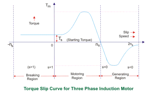
Fig. Torque slip characteristics
The torque-slip characteristic curve can be divided roughly into three regions:
1. Low slip region
2. Medium slip region
3. High slip region
Motoring Mode
1. In this mode of operation, supply is given to the stator sides and the motor always rotates below the synchronous speed. The induction motor torque varies from zero to full load torque as the slip varies. The slip varies from zero to one. It is zero at no load and one at standstill. From the curve, it is seen that the torque is directly proportional to the slip.
2. That is, more is the slip, more will be the torque produced, and vice-versa. The linear relationship simplifies the calculation of motor parameters to great extent.
Generating Mode
1. In this mode of operation induction motor runs above the synchronous speed and it should be driven by a prime mover.
2. The stator winding is connected to a three-phase supply in which it supplies electrical energy. Actually, in this case, the torque and slip both are negative so the motor receives mechanical energy and delivers electrical energy.
3. Induction motor is not much used as a generator because it requires reactive power for its operation.
4. That is, reactive power should be supplied from outside and if it runs below the synchronous speed by any means, it consumes electrical energy rather than giving it at the output. So, as far as possible, induction generators are generally avoided.
Braking Mode
1. In the Braking mode, the two leads or the polarity of the supply voltage is changed so that the motor starts to rotate in the reverse direction and as a result, the motor stops.
2. This method of braking is known as plugging. This method is used when it is required to stop the motor within a very short period.
3. The kinetic energy stored in the revolving load is dissipated as heat. Also, the motor is still receiving power from the stator which is also dissipated as heat.
4. So as a result of which motor develops enormous heat energy. For this stator is disconnected from the supply before the motor enters the braking mode.
5. If the load which the motor drives accelerates the motor in the same direction as the motor is rotating, the speed of the motor may increase more than synchronous speed. In this case, it acts as an induction generator that supplies electrical energy to the mains which tend to slow down the motor to its synchronous speed, in this case, the motor stops. This type of breaking principle is called dynamic or regenerative breaking.
Key takeaways:
1. The variation of slip can be obtained with the variation of speed that is when speed varies the slip will also vary and the torque corresponding to that speed will also vary.
2. The induction motor torque varies from zero to full load torque as the slip varies. The slip varies from zero to one.
3. Induction motor is not much used as a generator because it requires reactive power for its operation.
4.. If load which the motor drives accelerates the motor in the same direction as the motor is rotating, the speed of the motor may increase more than synchronous speed
1. When it comes to controlling an electric machine by electric drivers braking is a very important term because it helps to decrease the speed of the motor according to will and necessity. The braking of induction motors can be classified mainly into three types
Regenerative braking
1. Plugging or reverse voltage braking
2. Dynamic braking which can be further classified as
3. AC dynamic braking
4. Self-excited braking using capacitors
5. DC dynamic braking
6. Zero sequence braking
To explain that regeneration braking for induction motor, we can take help of the equation
1. Here, θs is the phase angle between the stator voltage and stator current, the simple words whenever this phase angle exceeds 90o (i.e θs>90o) regenerative braking can take place.
2. To explain this more clearly and easily we can say that whenever the speed of the rotor exceeds synchronous speed, regeneration braking occurs.
3. That is because whenever the rotor rotates at a speed more than synchronous speed there is a reverse field occurs which opposes the normal rotation of the motor and therefore braking takes place.
4. Main disadvantage of this type of braking is that the speed of the motor has to exceed synchronous speed which may not be possible every time. To acquire regenerative braking at a lower speed than synchronous speed, a variable frequency source can be used.
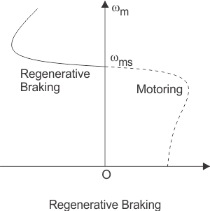
Fig. Braking graph
6. Plugging of induction motors is done by interchanging any two of the supply terminals. When the terminals have reversed the operation of the machine changes from motoring to plugging.
7. From a technical point of view and for better understanding it can be said that the slip changes from‘s’ to (2-s), which indicates that due to reversal of the terminals the torque also changes its direction and braking occurs.
8. The first classification of dynamic braking of induction motors is AC dynamic braking any one of the supply phases is disconnected from the supply and then it is either kept open or connected with the other phase.
9. The first type is known as two lead connections and the second one is known as three lead connections.
10. To understand this braking method we can assume the system to be a single-phase system. Now the motor can be considered to be fed by positive and negative sequence voltages. That’s why when the rotor resistance is high the net torque is negative and braking can be acquired.
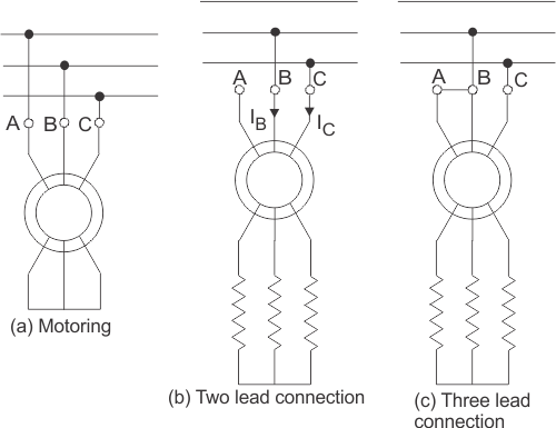
Fig. Braking systems in dynamic induction
11. Sometimes capacitors are kept permanent by connected across the supply terminals of the motor. This is called self-excited braking using capacitors of induction motors.
12. This type of braking works mainly by the property of the capacitors to store energy. Whenever the motor is disconnected from the supply the motor starts to work as a self-excited induction generator, the power comes from the capacitors connected across the terminals.
13. The values of the capacitor are so chosen that they are sufficient to make the motor work as an induction generator after being disconnected from the supply. When the motor works as an induction generator the produced torque opposes the normal rotation of the motor and hence braking takes place.
Speed control of induction motor
Speed control of induction motors can be done in six methods which are
1. Pole changing
2. Stator voltage control
3. Supply frequency control
4. Eddy current coupling
5. Rotor resistance control
1. We know that the speed of the induction motor is inversely proportional to several poles. So it is possible to increase or decrease the speed of the induction motor if the number of the poles is decreased or increased respectively.
2. The motor in which the provision of changing the number of poles is present, they are called ‘pole changing motor’ or ‘multi-speed motor’.
3. Another method of controlling the speed of induction motor drives is stator voltage control. Stator voltage is directly responsible for the rotating speed of the rotor.
4. Torque is proportional to voltage squared and the current is proportional to the voltage. So, if the stator voltage is reduced the speed reduces, and similarly if the stator voltage is increased the speed also increases.
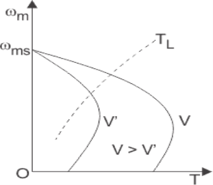
Fig. Speed control graph
5. The speed of an induction motor is proportional to the product of the supply frequency and air gap flux.
6. But as there is a chance of magnetic saturation while decreasing the supply frequency, that’s why not only the frequency but the v/f (i.e the ratio of supply voltage and frequency) is controlled and this ratio is tried to be kept constant. And if the speed is needed to be changed the ratio of v/f is changed accordingly.
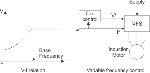
Fig. Voltage and frequency relation graph
7. The eddy current speed control method is done by placing an eddy current clutch between an induction motor is running at a fixed speed and the variable speed load. Now, what is this eddy current clutch?
8. It is nothing but an induction motor drive in which both the stator and the rotor are allowed to rotate. The rotor is coupled with the main induction motor.
9. When eddy currents are produced in the rotor drum, their interaction with the stator field and torque is produced which rotates the main motor. By controlling the DC current through the stator winding the speed of the motor can be controlled.
10. Depending on the rotor resistance, the speed of the rotor falls or increases. The variation of speed-torque characteristics with respect to change in rotor resistance is shown in the figures below.
11.This speed controlling method is better than many other methods because of its low cost
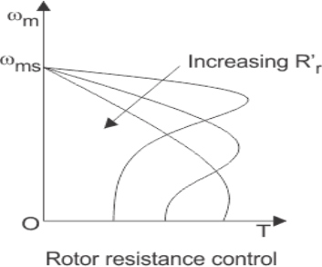
Fig. Resistance control graph
Key takeaways:
1. Torque is proportional to voltage squared and the current is proportional to the voltage. So, if the stator voltage is reduced the speed reduces, and similarly if the stator voltage is increased the speed also increases.
2. The speed of an induction motor is proportional to the product of the supply frequency and air gap flux.
3. By controlling the DC current through the stator winding the speed of the motor can be controlled.
No Load Test
1. The impedance of magnetizing path of the induction motor is large enough to obstruct the flow of current. Therefore, a small current is applied to the machine due to which there is a fall in the stator-impedance value, and rated voltage is applied across the magnetizing branch.
2. But the drop in stator-impedance value and power dissipated due to stator resistance is very small in comparison to the applied voltage. Therefore, their values are neglected and it is assumed that total power drawn is converted into core loss.
3. The air gap in a magnetizing branch in an induction motor slowly increases the exciting current and the no-load stator I2R loss can be recognized.
4. One should keep in mind that the current should not exceed its rated value otherwise rotor accelerates beyond its limit.
5. The test is performed at poly-phase voltages and rated frequency applied to the stator terminals. When the motor runs for some time and bearings get lubricated fully, at that time readings of applied voltage, input current, and input power are taken.
6. To calculate the rotational loss, subtract the stator I2R losses from the input power.

Fig. No-load test
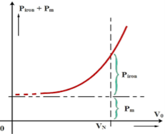
Fig. Graph for no-load test
Calculation of No-Load Test of Induction Motor
Let the total input power supplied to the induction motor be W0 watts.
W0 = √3 V1 I0 cos Ψ0 …….(1)
Where,
V1 = line voltage
I0 = No load input current
Rotational loss
Where,
S1 = stator winding loss
Nph = Number phase
The various losses like windage loss, core loss, and rotational loss are fixed losses that can be calculated by
Stator winding loss = 3Io2R1
Where,
I0 = No load input current
R1 = Resistance of the motor
Key takeaways:
1. The impedance of magnetizing path of induction motor is large enough to obstruct the flow of current
2. One should keep in mind that the current should not exceed its rated value otherwise rotor accelerates beyond its limit.
Blocked Rotor Test
1. The induction motors are widely used in industries and consume maximum power. To improve its performance characteristics certain tests have been designed like no-load test and block rotor test, etc.
2. A blocked rotor test is normally performed on an induction motor to find out the leakage impedance.
3. Apart from it, other parameters such as torque, motor, short-circuit current at normal voltage, and many more could be found from this test. The blocked rotor test is analogous to the short circuit test of the transformer.
4. Here shaft of the motor is clamped i.e. blocked so it cannot move and rotor winding is short-circuited.
5.In slip ring motor rotor winding is short-circuited through slip rings and in cage motors, rotor bars are permanently short-circuited.
6. The testing of the induction motor is a little bit complex as the resultant value of leakage impedance may get affected by rotor position, rotor frequency, and magnetic dispersion of the leakage flux path.
7.These effects could be minimized by conducting a blocking rotor current test on squirrel-cage rotors.
Process of Testing of Blocked Rotor Test of Induction Motor
1. In the blocked rotor test, it should be kept in mind that the applied voltage on the stator terminals should be low otherwise normal voltage could damage the winding of the stator.
2. In the block rotor test, the low voltage is applied so that the rotor does not rotate and its speed becomes zero and full load current passes through the stator winding.
3. The slip is unity related to zero speed of rotor hence the load resistance becomes zero. Now, slowly increase the voltage in the stator winding so that the current reaches its rated value.
4. At this point, note down the readings of the voltmeter, wattmeter, and ammeter to know the values of voltage, power, and current. The test can be repeated at different stator voltages for the accurate value.
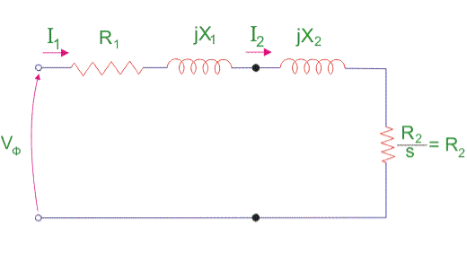
Fig. Block rotor test
5. Calculations of Blocked Rotor Test of Induction Motor
Resistance and Leakage Reactance Values
In blocked rotor test, core loss is very low due to the supply of low voltage and frictional loss is also negligible as the rotor is stationary, but stator copper losses and the rotor copper losses are reasonably high.
Let us take denote copper loss by W cu.
Therefore,
Wcu = Ws - Wc ........................(1)
Where Wc = core loss
Wcu = 3l2 R01 ..................(2)
Where R01 = Motor winding of stator and rotor as per phase referred to the stator.
Thus,
R01 = Wcu/3ls2 .................(3)
Now let us consider
Is = short circuit current
Vs = short circuit voltage
Z0 = short circuit impedance as referred to stator
Therefore,
Z01 =  ......................(4)
X01 = Motor leakage reactance per phase referred to stator can be calculated as
Stator reactance X1 and rotor reactance per phase referred to as stator X2 is normally assumed equal.
Therefore,
X01 = = √Z012 – R012 .................(5)
X1 = X2 = X01/2 .............................(6)
Similarly, stator resistance per phase R1 and rotor resistance per phase referred to stator R2 can be calculated as follows:
First, some suitable test is done on stator windings to find the value of R1 and then to find R2 subtract the R1 from R01
R2 = R01 – R1 ....................(7)
Short Circuit Current for Normal Supply Voltage
To calculate short circuit current Isc at normal voltage V of the stator, we must note short-circuit current Is and low voltage Vs applied to the stator winding.
Isc = Is (V/ Vs) ...................(8)
Key takeaways:
1. In the blocked rotor test, it should be kept in mind that the applied voltage on the stator terminals should be low otherwise normal voltage could damage the winding of the stator.
2. The testing of the induction motor is a little bit complex as the resultant value of leakage impedance may get affected by rotor position, rotor frequency, and magnetic dispersion of the leakage flux path.
3. To calculate short circuit current Isc at normal voltage V of the stator, we must note short-circuit current Is and low voltage Vs applied to the stator winding.
We classify starting methods for squirrel cage induction motor into two types based on voltage. The two types are:
1. Full voltage starting method
2. Reduced voltage method for starting squirrel cage induction motor.
Full Voltage Starting Method for Squirrel Cage Induction Motor
In this type, we have only one method of starting.
Direct on Line Starting Method
1. This method is also known as the DOL method for starting the three-phase squirrel cage induction motor. In this method, we directly switch the stator of the three-phase squirrel cage induction motor on to the supply mains.
2. The motor at the time of starting draws a very high starting current (about 5 to 7 times the full load current) for a very short duration.
3. The amount of current drawn by the motor depends upon its design and size. But such a high value of current does not harm the motor because of the rugged construction of the squirrel cage induction motor.
4. Such a high value of current causes sudden undesirable voltage drop in the supply voltage. A live example of this sudden drop of voltage is the dimming of the tube lights and bulbs in our homes at the instant of starting of refrigerator motor.
5. Now let us derive the expression for starting torque in terms of full load torque for the direct online starter. We have various quantities that involved in the expression for the starting torque are written below: We define Ts as starting torque
Tf as the full load torque
If as per phase rotor current at full load
Is as per phase rotor current at the time of starting
Sf as full load slip
Ss as starting slip
R2 as rotor resistance
Ws as the synchronous speed of the motor
Now we can directly write the expression for the torque of the induction motor as

From the help of the above expression, we write the ratio of starting torque to full load torque as

Here we have assumed that the rotor resistance is constant and it does not vary with the frequency of the rotor current.
Reduced voltage method for starting squirrel cage induction motor
In the reduced voltage method, we have three different types of starting method and these are written below:
1. Stator resistor starting method
2. Autotransformer staring method
3. Star delta starting method
Now let us discuss each of these methods in detail.
1. Stator Resistor Starting Method
Given below is the figure for the starting resistor method:
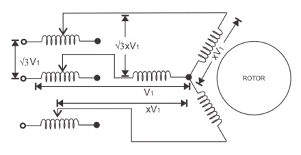
Fig. Stator resistor
1. In this method we add a resistor or a reactor in each phase as shown in the diagram (between the motor terminal and the supply mains). Thus by adding a resistor we can control the supply voltage.
2. Only a fraction of the voltage (x) of the supply voltage is applied at the time of starting of the induction motor. The value of x is always less than one.
3. Due to the drop in the voltage the starting torque also decreases. We will derive the expression for the starting torque in terms of the voltage fraction x to show the variation of the starting torque with the value of x.
4. As the motor speeds up the reactor or resistor is cut out from the circuit and finally, the resistors are short-circuited when the motor reaches its operating speed.
5. Now let us derive the expression for starting torque in terms of full load torque for the stator resistor starting method. We have various quantities that involved in the expression for the starting torque are written below: we define Ts as starting torque
Tf as the full load torque
If as per phase rotor current at full load
Is as per phase rotor current at the time of starting
Sf as full load slip
Ss as starting slip
R2 as rotor resistance
Ws as the synchronous speed of the motor
Now we can directly write the expression for the torque of the induction motor as

From the help of the above expression, we write the ratio of starting torque to full load torque as

Here we have assumed that the rotor resistance is constant and it does not vary with the frequency of the rotor current. From the above equation, we can have the expression for the starting torque in terms of the full load torque.
6. Now at the time of starting the per phase voltage is reduced to xV1, the per phase starting current is also reduced to xIs. On substituting the value of Is as xIs in the equation We have


7. This shows the variation of the starting torque with the value of x. Now there are some considerations regarding this method. If we add a series resistor then the energy losses are increased so it’s better to use a series reactor in place of a resistor because it is more effective in reducing the voltage however series reactor is more costly than the series resistance.
2. Auto Transformer Starting Method
1. As the name suggests in this method we connect the auto transformer in between the three-phase power supply and the induction motor as shown in the given diagram:
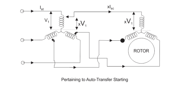
Fig. Stating of autotransformer
2. The autotransformer is a step-down transformer hence it reduces the per phase supply voltage from V1 to xV1. The reduction in voltage reduces current from Is to xIs.
3. After the motor reaches its normal operating speed, the autotransformer is disconnected and then full line voltage is applied.
3. Now let us derive the expression for starting torque in terms of full load torque for the autotransformer starting method. We have various quantities that involved in the expression for the starting torque are written below:
We define Ts as starting torque
Tf as the full load torque
If as per phase rotor current at full load
Is as per phase rotor current at the time of starting
Sf as full load slip
Ss as starting slip
R2 as rotor resistance
Ws as the synchronous speed of the motor
Now we can directly write the expression for the torque of the induction motor as

From the help of the above expression, we write the ratio of starting torque to full load torque as


4. Here we have assumed that the rotor resistance is constant and it does not vary with the frequency of the rotor current. From the above equation, we can have the expression for the starting torque in terms of the full load torque.
5. Now at the time of starting the per phase voltage is reduced to xV1, the per phase starting current is also reduced to xIs. On substituting the value of Is as xIs in equation 1. We have
This shows the variation of the starting torque with the value of x.
3. Star-Delta Starting Method
The connection diagram is shown below for the star-delta method,
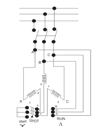
Fig. Star delta connection
1. This method is used for the motors designed to operate in delta connected winding. The terminals are marked for the phases of the stator are shown above. Now let us see this method works.
2.The stator phases are first connected to the star with the help of a triple pole double throw switch (TPDT switch) in the diagram the position is marked as 1 then after this when the steady-state speed is reached the switch is thrown to position 2 as shown in the above diagram.
3. Now, let analyze the working of the above circuit. In the first position, the terminals of the motor are short-circuited and in the second position from the diagram the terminal a, b and c are respectively connected to B, C, and A.
4. Now let us derive the expression for starting torque in terms of full load torque for the star-delta starting method. We have various quantities that involved in the expression for the starting torque are written below
Tf as the full load torque
Ts as starting torque
If as per phase rotor current at full load
Is as per phase rotor current at the time of starting
Sf as full load slip
Ss as starting slip
R2 as rotor resistance
Ws as the synchronous speed of the motor
Now we can directly write the expression for the torque of the induction motor as

From the help of the above expression, we write the ratio of starting torque to full load torque as

5. Here we have assumed that the rotor resistance is constant and it does not vary with the frequency of the rotor current. Let us assume the line voltage to be Vl then the per phase starting current when connected in star position is Iss which is given by

When the stator is in delta connected position we have starting current

From the above equation we have

6. This shows that the reduced voltage method has the advantage of reducing the starting current but the disadvantage is that all these methods of reduced voltage cause the objectionable reduction in the starting torque.
Key takeaways:
1. In DOL the amount of current drawn by the motor depends upon its design and size
2. In the stator resistor starting method Due to the drop in the voltage the starting torque also decreases.
3. In autotransformer starting method. After the motor reaches its normal operating speed, the autotransformer is disconnected and then full line voltage is applied.
4.star delta starting method is used for the motors designed to operate in delta connected winding.
Induction generators are used principally with alternative energy sources such as windmills or wind energy recovery systems for large scale power generation. They are also used to supply additional power to a load in a remote area that is being supplied by a weak transmission line.
Example
A 10 hp, 1760 rpm, 440V, three-phase induction motor operates as an asynchronous generator. The full load current of the motor is 10 A and the full load power factor is 0.8. Determine the required capacitors per phase if capacitors are connected in delta.
Answer-
Apparent power


Active power


Reactive power


For a machine to run as an asynchronous generator, capacitor bank must supply a minimum  VAR per phase
Capacitive current 

Capacitive reactance per phase 
Minimum capacitance per phase


If the load also absorbs reactive power, the capacitor bank must be increased in size to compensate.
Prime mover speed should be used to generate a frequency of 50 Hertz.
CASE STUDY
Driver Circuit for Stepper Motor
Steppers are special motors that do not have any commutator to reverse flow of the windings current. Stepper motors are the best alternatives for applications that high-accuracy motions are required such as CNC, printers and so on. Because of the simple winding and control system, the main applications of these motors are the motion controls. On the basis of the motor structure and operation, stepper motors are divided into three types: permanent magnet (PM), variable reluctance (VR) and hybrids. There is special procedure for driving each of them. In general, stepper motors are driving in full-, half- and micro-step modes. In full-step mode, to change rotor position completely, activation and deactivation signals are fed to the windings alternatively in each cycle.
In half-step, each winding can stay activated for more than on cycle. Therefore, the rotor motion is half of the full-step and the motor resolution is two times more. Micro-step driving is another alternative for motor motion that has more accuracy and continuous motion. Two main advantage of micro-step mode is the possibility for rotor to move between full and half modes and to eliminate irregular characteristics of motor torque. Stepper motor driver circuit implementation process for all three modes is
Presented. For design testing, appropriate driving signal patterns are generated using PC parallel port. Torque tests are applied to the driver circuit and experimental results extracted. As obtained, using micro-step driving, stepper motor rotates more continuously. Also, irregular torque values (appeared like holes in torque curve at resonance frequencies) are eliminated.
Control Circuit
Generally, control and driving techniques for stepper motors are categorized in open- and close-loop modes (here, open-loop mode is considered). In stepper motors, driving is done by activation and deactivation of various windings. In general stepper motor driver circuit is divided into two main parts: signaling and switching [8]. Signaling part is for generating the consequent and regular pulses (patterns) for motor driver. The switching part turns the control switches on and off according to the generated patterns. A four-phase stepper motor driver has two main parts as follows: control signal sequencer and motor driver
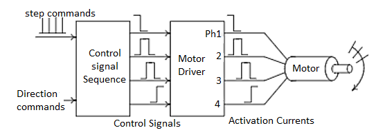
Fig. Driver Circuit
According to the nature of the windings, the current and therefore the switch state could not change suddenly except that infinite opposite voltage is applied to the winding. When the control switch of the winding is closed, the winding current increased gradually. Thus, when its state change (the switch opened), large voltage is applied to the winding. This may damage the control switches if there is no care about it. There are two main strategies to solve these problems: using diode or capacitance in parallel with the
Winding. There are several driving techniques for every type of the stepper motors. Consider a bipolar HBridge hybrid motor, as shown in Fig2. Reversing the magnet field direction, one can change the winding current flow. Achieving this, one can arrange the control switches like H letter (called H-Bridge) and put the winding between them.
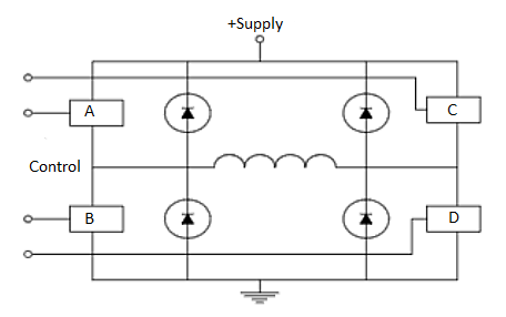
Fig. Bridge Hybrid Model
Because of four control switches, H-Bridge can have 16 different modes of operations. Some of
Them are not used generally. Some of the practical operation modes are as follows
- Forward: only A and D switches are closed.
- Reverse: only B and C switches are closed.
- Fast Decay: All switches are closed and the winding current decreased through the power
- Supply and diodes path. This mode doesn’t damage the winding and therefore the rotor can move freely without any resistance.
- Slow Decay: In this mode, the current is passed through the motor winding rotationally without any resistance. Therefore, if a few current remains in winding, this operation caused the current dissipated and the rotor stopped slowly.
It is possible that activation of control switches in H-Bridges caused short-circuit between power supplies (i.e. closing switches A and B). In these cases, usually logic gates used to eliminate short-circuit effects. Fig 3 shows the sample circuit where this technique is applied.

Fig. SC elimination from H bridge
As shown above, all of the operation modes can be accessible only with a few numbers of signals.
This is so practical when we use microcontrollers or microprocessors for control signal (pattern)
Generation (i.e. X and Y signals on the above).
Micro-step driving circuit
In micro-step mode[7], the resolution (number of steps per round) is increased. The motor used pass 1.8 degree per rotation and has resolution equals to 200 steps. After micro-step driving, the target becomes 800 steps per rotation (4 micro-steps per each step). After driver implementation for half- and full-step modes, several parts should be changed and optimized for micro-step driving. One of the main parts is the reference voltage (Vref). Another optimization is to control two phase of the motor independently. For this purpose, driver circuit must be changed to be able to control the winding current independently to the portion of the final phase current. For this, one can control the current of the motor phases to be able to move between two full steps more. According to this, digital to analog converter (DAC) and operational amplifiers (OpAmp) are used to control the reference voltage of the motor. Inputs to the ADC will determined the signal levels and the bit number can perform more accurately. Two L297 devices are used to control the L298 phases separately. These devices should be synchronized by each other. The inhibit output signals of each L297 (INH) control corresponding enable (EN) lines of the L298 (ENA and ENB).
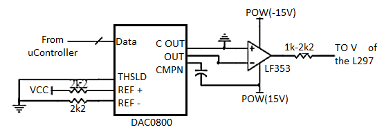
Fig. Micro-step driving circuit
References
1. I. J. Nagrath, D.P. Kothari, “Electrical Machines,”, Tata McGraw- Hill Publishing
Company Ltd.
2. P.S. Bhimbra,”Electrical Machinery”, Khanna Publishers.
3. P.K. Mukherjee, S. Chakrabvorty, “Electrical Machines”, Dhanpat Rai Publications.
4. P.S. Bhimbra, “Generalized Theory in Electrical Machines”, Khanna Publishers.
5. D C Kulshreshtha, “Basic Electrical Engineering,” The McGraw Hill Higher Education Private Limited, New Delhi.
Unit - 3
Three Phase Induction Motor
Consider- 3Фslip ring I.M
Cut section diagram: -
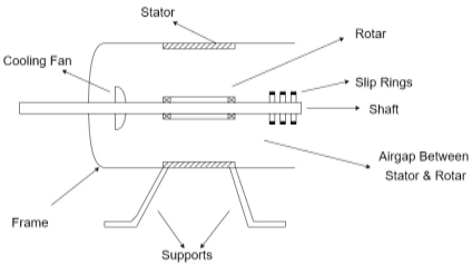
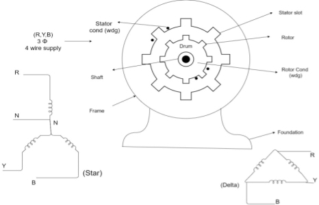
The induction motor has following important parts:
- Stator: it is the stationary part of induction motor and it is one of important part in induction motor.
- Rotor: the rotor is the rotating part of induction motor which consists of rotor wdg.
- Stator winding: this wdg. Is mounted on devastator and it generates the RMF i.e. rotating magnetic field.
- Rotor winding:- rotor winding is used to rotate the shaft of motor. This wdgis provided on rotor
- Frame :- it provides the mechanical support to the motor. It is the outer covering of motor. It protects the internal parts of motor from damage.
- Shaft:- shaft is used to connect to the load and four rotation.
- Slip rings and brushes:- slip rings are mounted on the shaft which is connected with brushes from which connection is given to the external resistant or rheostat
- Cooling fan:- this is provided for cooling purpose of motor and its internal parts.
Principle of operation of induction motor:
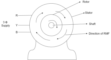
- When the 3ФA.C supply is connected across the stator of induction motor, the current starts flowing through the stator wdg. i.e the stator condition.
- Due to this current of flux (Ф) is established in the stator wdg. This flux (Ф) is alternating (changing) in nature. Thus this flux links with the rotor also, and a a Rotating Magnetic Field (RMF) is produced.
- This flux (Ф) induces in the rotor also. The RMF is produced in the air gap between stator and rotor.
- The rotor is rotating part which is till stationary, show the rotating magnetic field is cut by stationary rotor and an EMF is induced in the rotor winding. According to faraday's law of EMI the rotor EMF gives the rise to rotor current which opposes the main cause producing it according Lenz's law.
Types of induction motor:
Two main types depending upon the rotor
- Squirrel cage induction motor (squirrel cage rotor)
- Slip ring induction motor(slip ring or wound rotor)
Induction motor are also available in 1Фsupply i.e.
1. Resistance split phase induction motor
2. Capacitor start induction motor
3. Capacitor start capacitor run induction motor
4. 1Фinduction motor i.e. A.C series motors
5. Shaded pole induction motor
Torque equation of induction motor:
Torque produced in induction motor depends upon the following factors
1.The rotor power factors ( CosФ) under running condition
2.The rotor current under running condition
3. The part of RMF which induces EMF in rotor wdgi.e. flux (Ф)
We can mathematically say that,
T ∝ ϕ Ia , As per DC (M) equation
But in case of induction motor
Suffix 1 -> used for stator/stator parts (qty)
Suffix 2-> used for rotor/rotor parts(qty)
Therefore, T ∝ ϕ I2r cos ϕ2r----(1)
ϕ = flux that induces the EMF in rotor
l2r = rotor current under running condition
Cos ϕ2r = P.F of rotor
But,ϕ ∝ stator vtg E1 also i.e
ϕ ∝ E1----(2)
Transformation ratio i.e. given by K = 
Therefore,
E2 ∝ E1 and hence
E2 ∝ ϕ also
E2 at slip ’S’ is given by E2 = SE2
And also X2 at slip ‘S’ is X2 = S X2
Hence ϕ in equation can be replaced by E2
i.e. T ∝ E2 I2r cos ϕ2rU
 ----(3)----(
4 cos ϕ2r =  ------(4)
Subtract (3) and (4) into (1) equation we get,
T ∝ E2 
T ∝ 
T =  (N-m) , Torque equation of I.M.
K =  Ns’ =
Ns’ = 
T = 

At starting condition slip S=1
So, T = 

The torque developed at the moment when motor starts is called as starting torque. As we already know the motor torque Taαφ Ia. An induction motor develops gross torque Tg due to gross rotor output Pm. Then in terms of rotor input
Tg= 
In terms of rotor output the gross torque is Tg= 
Due to rotor friction and windage losses the shaft torque Tsh is less than Pm
Tsh=  (N, Ns are in rpm)
Tg =  N-m
N-m
Tsh = = 
For induction motor the torque is also proportional to the product of flux per stator pole and the rotor current, in addition to the power factor.
Starting Torque
T αφ I2 cos φ2
Or T=k φ I2 cos φ2
I2=rotor current at standstill
φ2=angle between rotor emf and rotor current
E2=rotor emf at standstill.
Also, E2αφ
So, T α E2I2 cos φ2
T=k1 E2I2 cos φ2
The starting torque Tst= k1 E2I2 cos φ2
From above section we know, I2 = Iz = E2/Z2 =  , cosφ2=R2/Z2=
  ,
,
Tst= k1 E2  .
.
For supply voltage constant, flux and E2 both are constant
Tst= 
k1=3/2πNs
Therefore, Tst=3/2πNs 
Torque-Slip Relation:
The torque slip characteristics is shown below. For low value of slip the curve is approximately a straight line. As slip increases the torque also increases and becomes maximum when s= R2/X2. This torque is called pull-out or breakdown torque Tb. From above section we already know
T= 
T α 
When slip increases more with motor load R2 becomes negligible. So, for large value of slip
T α 
Key takeaway
Tg== 
Tg  N-m
N-m
Tst= 3/2πNs 
T= = 
Starting torque and maximum torque
Starting torque is given as Tst= 
Maximum Torque Tmax =k1
Tst α
Tmax α 

a = 
Full load torque and maximum torque
Let sf be slip for full load torque.
Tfα 
Tmax α 

Dividing numerator and denominator by 

Key takeaway
Starting torque and maximum torque

Full load torque and maximum torque

Que) A 12-pole, 3-phase, 600V, 50Hz, star connected induction motor has rotor-resistance and standstill reactance of 0.04 and 0.6 ohm per phase respectively. Calculate i) speed of max. Torque ii) ratio of full load torque to max torque, if full load speed is 495rpm?
Sol: Ns=120f/P=120 x 50/12=500 rpm
For r=0.04 and x=0.6 ohm, slip torque is
Smt=a=r/x=0.04/0.6=0.067
i) Speed =(1-Smt)N=(1-0.067) x 500=466.67 rpm
Ii) Full load speed = 495rpm, slip=0.01, at full-load

Que) A 3-phase 400/200V, Y-Y connected wound rotor induction motor has 0.05 ohms resistance and 0.2 ohm stand still reactance per phase. Find the additional resistance required in the rotor circuit to make starting torque equal to the maximum torque of motor?
Sol:

Given Tst=Tmax
1=  , a=1
, a=1
a= 
1= 
r=0.15 Ω
Que: A 50hz ,6-pole induction motor has full load slip of 4%. The rotor resistance/phase = 0.02ohm and standstill reactance/phase=0.1 ohm. Find the ratio of maximum to full load torque and the speed at which the maximum torque occurs?
Sol:

a=R2/X2=0.02/0.1=0.02
 = 0.8
= 0.8
Ns = 120 x 50/6 = 1000rpm, sm= a(for maximum torque) = 0.02
N = (1-0.02) x 1000 = 980rpm
Torque of rotor in running condition is given as
T=  =
= 
Condition for maximum torque will be obtained by differentiating the above equation, we will get 


s=R2/X2
When rotor resistance per phase is equal to rotor reactance per phase under running condition, we have maximum torque. The above torque equation can be written as
Tmax = k1 
k1= 3/ 2πNs
Hence, maximum torque is given as
Tmax = 3/ 2πNs  N-m
N-m
Que) A 3-phase induction motor star connected rotor has an induced emf of 70volts between slip rings at standstill on open circuit. The rotor has a resistance and reactance per phase of 1ohm and 5ohm respectively. Calculate current/phase and power factor when slip rings are short circuited?
Sol: Standstill emf/rotor phase=70/√3 = 40.4 V
Rotor impedance/phase= √(12 + 52 = 5.09 ohm
Rotor current/phase=40.4/5.09=7.92A
Power factor cosφ=0.99
Que) A 3-phase induction motor star connected rotor has an induced emf of 70volts between slip rings at standstill on open circuit. The rotor has a resistance and reactance per phase of 1ohm and 5ohm respectively. Calculate current/phase and power factor when slip rings are connected to star connected rheostat of 2ohm?
Sol: Rotor resistance/phase=2+1 = 3 ohm
Rotor impedance/phase = √(32+52)= 5.83 ohm
Rotor current/phase = (70/√3 )/5.83 = 6.93A
Cosφ=3/5.83=0.514
Que) A 6-pole, 3-phase induction motor operates from a supply whose frequency is 50Hz. Calculate i) speed at which the magnetic field of stator is rotating. Ii)speed of rotor when slip is 4%. Iii)frequency of rotor current when slip is 3%?
Sol: i) Stator revolves at synchronous speed. So, Ns=120f/P=120 x 50/6=1000rpm
Ii)rotor speed N=(1-s)Ns=(1-0.04) x 1000=960rpm
Iii)frequency of rotor current f’=sf=0.03 x 50=90rpm
Two types of losses occur in a three-phase induction motor. These losses are,
1 Constant or fixed losses
2 Variable losses
3. Constant or Fixed Losses
Constant or fixed losses
Constant losses are those losses that are considered to remain constant over the normal working range of the induction motor. The fixed losses can be easily obtained by performing a no-load test on the three-phase induction motor. These losses are further classified as-
1. Iron or core losses,
2. Mechanical losses,
3. Brush friction losses.
1. Iron or Core Losses
1. Iron or core losses are further divided into hysteresis and eddy current losses. Eddy current losses are minimized by using lamination on the core.
2. Since by laminating the core, the area decreases, and hence resistance increases, which results in a decrease in eddy currents. Hysteresis losses are minimized by using high-grade silicon steel.
3. The core losses depend upon the frequency of the supply voltage. The frequency of stator is always supply frequency, f and the frequency of rotor is slip times the supply frequency, (sf) which is always less than the stator frequency.
4. For stator frequency of 50 Hz, rotor frequency is about 1.5 Hz because under normal running conditions slip is of the order of 3 %. Hence the rotor core loss is very small as compared to stator core loss and is usually neglected in running conditions.
2. Mechanical and Brush Friction Losses
1. Mechanical losses occur at the bearing and brush friction loss occurs in the wound rotor induction motor. These losses are zero at the start and with an increase in speed these losses increase.
2. In a three-phase induction motor the speed usually remains constant.
3. Hence these losses almost remain constant.
Variable Losses
1. These losses are also called copper losses. These losses occur due to the current flowing in stator and rotor windings.
2. As the load changes, the current flowing in rotor and stator winding also changes, and hence these losses also change. Therefore these losses are called variable losses.
3. The copper losses are obtained by performing a blocked rotor test on a three-phase induction motor. The main function of an induction motor is to convert electrical power into mechanical power.
4. During this conversion of electrical energy into mechanical energy the power flows through different stages.
5. This power flowing through different stages is shown by the power flow diagram. As we all know the input to the three-phase induction motor is a three-phase supply.
6. So, the three-phase supply is given to the stator of the three-phase induction motor.
Let, Pin = electrical power supplied to the stator of three-phase induction motor,
VL = line voltage supplied to the stator of three-phase induction motor,
IL = line current,
Cosφ = power factor of the three-phase induction motor.
Electrical power input to the stator, Pin = √3VLILcosφ
A part of this power input is used to supply stator losses which are stator iron loss and stator copper loss. The remaining power i.e (input electrical power – stator losses) is supplied to the rotor as rotor input.
So, rotor input P2 = Pin – stator losses (stator copper loss and stator iron loss).
7. Now, the rotor has to convert this rotor input into mechanical energy but this complete input cannot be converted into mechanical output as it has to supply rotor losses. As explained earlier the rotor losses are of two types rotor iron loss and rotor copper loss.
8. Since the iron loss depends upon the rotor frequency, which is very small when the rotor rotates, so it is usually neglected. So, the rotor has only rotor copper loss.
9. Therefore the rotor input has to supply these rotor copper losses. After supplying the rotor copper losses, the remaining part of Rotor input, P2 is converted into mechanical power, Pm.
10. Now this mechanical power developed is given to the load by the shaft but there occur some mechanical losses like friction and windage losses. So, the gross mechanical power developed has to be supplied to these losses. Therefore the net output power developed at the shaft, which is finally given to the load is Pout.
Pout = Pm – Mechanical losses (friction and windage losses).
Pout is called the shaft power or useful power.

Fig. Power flow diagram
Efficiency
The efficiency of 3 phase induction motor:
Efficiency is defined as the ratio of output to that of input

Rotor efficiency of 3 phase induction motor

Gross mechanical power developed /rotor input

Three-phase induction motor efficiency

Three-phase induction motor efficiency

Key takeaways:
1. The core losses depend upon the frequency of the supply voltage. The frequency of stator is always supply frequency
2. These losses are zero at the start and with an increase in speed these losses increase.
3. The copper losses are obtained by performing a blocked rotor test on a three-phase induction motor. The main function of an induction motor is to convert electrical power into mechanical power.
Torque Slip Characteristics of Three Phase Induction Motor
1. The torque slip curve for an induction motor gives us information about the variation of torque with the slip.
2. The slip is defined as the ratio of the difference of synchronous speed and actual rotor speed to the synchronous speed of the machine.
3. The variation of slip can be obtained with the variation of speed that is when speed varies the slip will also vary and the torque corresponding to that speed will also vary.
The curve can be described in three modes of operation-

Fig. Torque slip characteristics
The torque-slip characteristic curve can be divided roughly into three regions:
1. Low slip region
2. Medium slip region
3. High slip region
Motoring Mode
1. In this mode of operation, supply is given to the stator sides and the motor always rotates below the synchronous speed. The induction motor torque varies from zero to full load torque as the slip varies. The slip varies from zero to one. It is zero at no load and one at standstill. From the curve, it is seen that the torque is directly proportional to the slip.
2. That is, more is the slip, more will be the torque produced, and vice-versa. The linear relationship simplifies the calculation of motor parameters to great extent.
Generating Mode
1. In this mode of operation induction motor runs above the synchronous speed and it should be driven by a prime mover.
2. The stator winding is connected to a three-phase supply in which it supplies electrical energy. Actually, in this case, the torque and slip both are negative so the motor receives mechanical energy and delivers electrical energy.
3. Induction motor is not much used as a generator because it requires reactive power for its operation.
4. That is, reactive power should be supplied from outside and if it runs below the synchronous speed by any means, it consumes electrical energy rather than giving it at the output. So, as far as possible, induction generators are generally avoided.
Braking Mode
1. In the Braking mode, the two leads or the polarity of the supply voltage is changed so that the motor starts to rotate in the reverse direction and as a result, the motor stops.
2. This method of braking is known as plugging. This method is used when it is required to stop the motor within a very short period.
3. The kinetic energy stored in the revolving load is dissipated as heat. Also, the motor is still receiving power from the stator which is also dissipated as heat.
4. So as a result of which motor develops enormous heat energy. For this stator is disconnected from the supply before the motor enters the braking mode.
5. If the load which the motor drives accelerates the motor in the same direction as the motor is rotating, the speed of the motor may increase more than synchronous speed. In this case, it acts as an induction generator that supplies electrical energy to the mains which tend to slow down the motor to its synchronous speed, in this case, the motor stops. This type of breaking principle is called dynamic or regenerative breaking.
Key takeaways:
1. The variation of slip can be obtained with the variation of speed that is when speed varies the slip will also vary and the torque corresponding to that speed will also vary.
2. The induction motor torque varies from zero to full load torque as the slip varies. The slip varies from zero to one.
3. Induction motor is not much used as a generator because it requires reactive power for its operation.
4.. If load which the motor drives accelerates the motor in the same direction as the motor is rotating, the speed of the motor may increase more than synchronous speed
1. When it comes to controlling an electric machine by electric drivers braking is a very important term because it helps to decrease the speed of the motor according to will and necessity. The braking of induction motors can be classified mainly into three types
Regenerative braking
1. Plugging or reverse voltage braking
2. Dynamic braking which can be further classified as
3. AC dynamic braking
4. Self-excited braking using capacitors
5. DC dynamic braking
6. Zero sequence braking
To explain that regeneration braking for induction motor, we can take help of the equation
1. Here, θs is the phase angle between the stator voltage and stator current, the simple words whenever this phase angle exceeds 90o (i.e θs>90o) regenerative braking can take place.
2. To explain this more clearly and easily we can say that whenever the speed of the rotor exceeds synchronous speed, regeneration braking occurs.
3. That is because whenever the rotor rotates at a speed more than synchronous speed there is a reverse field occurs which opposes the normal rotation of the motor and therefore braking takes place.
4. Main disadvantage of this type of braking is that the speed of the motor has to exceed synchronous speed which may not be possible every time. To acquire regenerative braking at a lower speed than synchronous speed, a variable frequency source can be used.
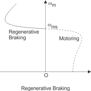
Fig. Braking graph
6. Plugging of induction motors is done by interchanging any two of the supply terminals. When the terminals have reversed the operation of the machine changes from motoring to plugging.
7. From a technical point of view and for better understanding it can be said that the slip changes from‘s’ to (2-s), which indicates that due to reversal of the terminals the torque also changes its direction and braking occurs.
8. The first classification of dynamic braking of induction motors is AC dynamic braking any one of the supply phases is disconnected from the supply and then it is either kept open or connected with the other phase.
9. The first type is known as two lead connections and the second one is known as three lead connections.
10. To understand this braking method we can assume the system to be a single-phase system. Now the motor can be considered to be fed by positive and negative sequence voltages. That’s why when the rotor resistance is high the net torque is negative and braking can be acquired.
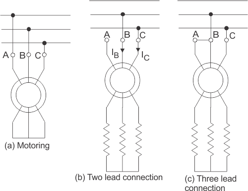
Fig. Braking systems in dynamic induction
11. Sometimes capacitors are kept permanent by connected across the supply terminals of the motor. This is called self-excited braking using capacitors of induction motors.
12. This type of braking works mainly by the property of the capacitors to store energy. Whenever the motor is disconnected from the supply the motor starts to work as a self-excited induction generator, the power comes from the capacitors connected across the terminals.
13. The values of the capacitor are so chosen that they are sufficient to make the motor work as an induction generator after being disconnected from the supply. When the motor works as an induction generator the produced torque opposes the normal rotation of the motor and hence braking takes place.
Speed control of induction motor
Speed control of induction motors can be done in six methods which are
1. Pole changing
2. Stator voltage control
3. Supply frequency control
4. Eddy current coupling
5. Rotor resistance control
1. We know that the speed of the induction motor is inversely proportional to several poles. So it is possible to increase or decrease the speed of the induction motor if the number of the poles is decreased or increased respectively.
2. The motor in which the provision of changing the number of poles is present, they are called ‘pole changing motor’ or ‘multi-speed motor’.
3. Another method of controlling the speed of induction motor drives is stator voltage control. Stator voltage is directly responsible for the rotating speed of the rotor.
4. Torque is proportional to voltage squared and the current is proportional to the voltage. So, if the stator voltage is reduced the speed reduces, and similarly if the stator voltage is increased the speed also increases.
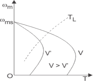
Fig. Speed control graph
5. The speed of an induction motor is proportional to the product of the supply frequency and air gap flux.
6. But as there is a chance of magnetic saturation while decreasing the supply frequency, that’s why not only the frequency but the v/f (i.e the ratio of supply voltage and frequency) is controlled and this ratio is tried to be kept constant. And if the speed is needed to be changed the ratio of v/f is changed accordingly.
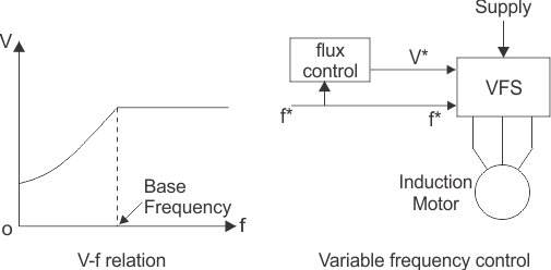
Fig. Voltage and frequency relation graph
7. The eddy current speed control method is done by placing an eddy current clutch between an induction motor is running at a fixed speed and the variable speed load. Now, what is this eddy current clutch?
8. It is nothing but an induction motor drive in which both the stator and the rotor are allowed to rotate. The rotor is coupled with the main induction motor.
9. When eddy currents are produced in the rotor drum, their interaction with the stator field and torque is produced which rotates the main motor. By controlling the DC current through the stator winding the speed of the motor can be controlled.
10. Depending on the rotor resistance, the speed of the rotor falls or increases. The variation of speed-torque characteristics with respect to change in rotor resistance is shown in the figures below.
11.This speed controlling method is better than many other methods because of its low cost
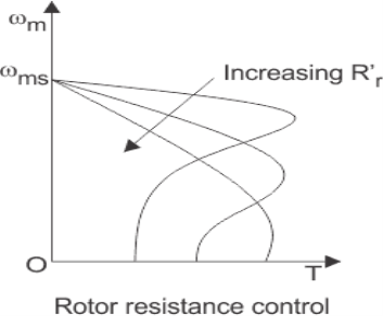
Fig. Resistance control graph
Key takeaways:
1. Torque is proportional to voltage squared and the current is proportional to the voltage. So, if the stator voltage is reduced the speed reduces, and similarly if the stator voltage is increased the speed also increases.
2. The speed of an induction motor is proportional to the product of the supply frequency and air gap flux.
3. By controlling the DC current through the stator winding the speed of the motor can be controlled.
No Load Test
1. The impedance of magnetizing path of the induction motor is large enough to obstruct the flow of current. Therefore, a small current is applied to the machine due to which there is a fall in the stator-impedance value, and rated voltage is applied across the magnetizing branch.
2. But the drop in stator-impedance value and power dissipated due to stator resistance is very small in comparison to the applied voltage. Therefore, their values are neglected and it is assumed that total power drawn is converted into core loss.
3. The air gap in a magnetizing branch in an induction motor slowly increases the exciting current and the no-load stator I2R loss can be recognized.
4. One should keep in mind that the current should not exceed its rated value otherwise rotor accelerates beyond its limit.
5. The test is performed at poly-phase voltages and rated frequency applied to the stator terminals. When the motor runs for some time and bearings get lubricated fully, at that time readings of applied voltage, input current, and input power are taken.
6. To calculate the rotational loss, subtract the stator I2R losses from the input power.
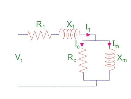
Fig. No-load test
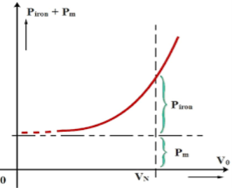
Fig. Graph for no-load test
Calculation of No-Load Test of Induction Motor
Let the total input power supplied to the induction motor be W0 watts.
W0 = √3 V1 I0 cos Ψ0 …….(1)
Where,
V1 = line voltage
I0 = No load input current
Rotational loss
Where,
S1 = stator winding loss
Nph = Number phase
The various losses like windage loss, core loss, and rotational loss are fixed losses that can be calculated by
Stator winding loss = 3Io2R1
Where,
I0 = No load input current
R1 = Resistance of the motor
Key takeaways:
1. The impedance of magnetizing path of induction motor is large enough to obstruct the flow of current
2. One should keep in mind that the current should not exceed its rated value otherwise rotor accelerates beyond its limit.
Blocked Rotor Test
1. The induction motors are widely used in industries and consume maximum power. To improve its performance characteristics certain tests have been designed like no-load test and block rotor test, etc.
2. A blocked rotor test is normally performed on an induction motor to find out the leakage impedance.
3. Apart from it, other parameters such as torque, motor, short-circuit current at normal voltage, and many more could be found from this test. The blocked rotor test is analogous to the short circuit test of the transformer.
4. Here shaft of the motor is clamped i.e. blocked so it cannot move and rotor winding is short-circuited.
5.In slip ring motor rotor winding is short-circuited through slip rings and in cage motors, rotor bars are permanently short-circuited.
6. The testing of the induction motor is a little bit complex as the resultant value of leakage impedance may get affected by rotor position, rotor frequency, and magnetic dispersion of the leakage flux path.
7.These effects could be minimized by conducting a blocking rotor current test on squirrel-cage rotors.
Process of Testing of Blocked Rotor Test of Induction Motor
1. In the blocked rotor test, it should be kept in mind that the applied voltage on the stator terminals should be low otherwise normal voltage could damage the winding of the stator.
2. In the block rotor test, the low voltage is applied so that the rotor does not rotate and its speed becomes zero and full load current passes through the stator winding.
3. The slip is unity related to zero speed of rotor hence the load resistance becomes zero. Now, slowly increase the voltage in the stator winding so that the current reaches its rated value.
4. At this point, note down the readings of the voltmeter, wattmeter, and ammeter to know the values of voltage, power, and current. The test can be repeated at different stator voltages for the accurate value.
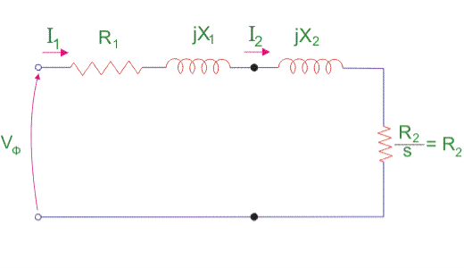
Fig. Block rotor test
5. Calculations of Blocked Rotor Test of Induction Motor
Resistance and Leakage Reactance Values
In blocked rotor test, core loss is very low due to the supply of low voltage and frictional loss is also negligible as the rotor is stationary, but stator copper losses and the rotor copper losses are reasonably high.
Let us take denote copper loss by W cu.
Therefore,
Wcu = Ws - Wc ........................(1)
Where Wc = core loss
Wcu = 3l2 R01 ..................(2)
Where R01 = Motor winding of stator and rotor as per phase referred to the stator.
Thus,
R01 = Wcu/3ls2 .................(3)
Now let us consider
Is = short circuit current
Vs = short circuit voltage
Z0 = short circuit impedance as referred to stator
Therefore,
Z01 =  ......................(4)
X01 = Motor leakage reactance per phase referred to stator can be calculated as
Stator reactance X1 and rotor reactance per phase referred to as stator X2 is normally assumed equal.
Therefore,
X01 = = √Z012 – R012 .................(5)
X1 = X2 = X01/2 .............................(6)
Similarly, stator resistance per phase R1 and rotor resistance per phase referred to stator R2 can be calculated as follows:
First, some suitable test is done on stator windings to find the value of R1 and then to find R2 subtract the R1 from R01
R2 = R01 – R1 ....................(7)
Short Circuit Current for Normal Supply Voltage
To calculate short circuit current Isc at normal voltage V of the stator, we must note short-circuit current Is and low voltage Vs applied to the stator winding.
Isc = Is (V/ Vs) ...................(8)
Key takeaways:
1. In the blocked rotor test, it should be kept in mind that the applied voltage on the stator terminals should be low otherwise normal voltage could damage the winding of the stator.
2. The testing of the induction motor is a little bit complex as the resultant value of leakage impedance may get affected by rotor position, rotor frequency, and magnetic dispersion of the leakage flux path.
3. To calculate short circuit current Isc at normal voltage V of the stator, we must note short-circuit current Is and low voltage Vs applied to the stator winding.
We classify starting methods for squirrel cage induction motor into two types based on voltage. The two types are:
1. Full voltage starting method
2. Reduced voltage method for starting squirrel cage induction motor.
Full Voltage Starting Method for Squirrel Cage Induction Motor
In this type, we have only one method of starting.
Direct on Line Starting Method
1. This method is also known as the DOL method for starting the three-phase squirrel cage induction motor. In this method, we directly switch the stator of the three-phase squirrel cage induction motor on to the supply mains.
2. The motor at the time of starting draws a very high starting current (about 5 to 7 times the full load current) for a very short duration.
3. The amount of current drawn by the motor depends upon its design and size. But such a high value of current does not harm the motor because of the rugged construction of the squirrel cage induction motor.
4. Such a high value of current causes sudden undesirable voltage drop in the supply voltage. A live example of this sudden drop of voltage is the dimming of the tube lights and bulbs in our homes at the instant of starting of refrigerator motor.
5. Now let us derive the expression for starting torque in terms of full load torque for the direct online starter. We have various quantities that involved in the expression for the starting torque are written below: We define Ts as starting torque
Tf as the full load torque
If as per phase rotor current at full load
Is as per phase rotor current at the time of starting
Sf as full load slip
Ss as starting slip
R2 as rotor resistance
Ws as the synchronous speed of the motor
Now we can directly write the expression for the torque of the induction motor as

From the help of the above expression, we write the ratio of starting torque to full load torque as

Here we have assumed that the rotor resistance is constant and it does not vary with the frequency of the rotor current.
Reduced voltage method for starting squirrel cage induction motor
In the reduced voltage method, we have three different types of starting method and these are written below:
1. Stator resistor starting method
2. Autotransformer staring method
3. Star delta starting method
Now let us discuss each of these methods in detail.
1. Stator Resistor Starting Method
Given below is the figure for the starting resistor method:
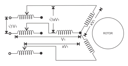
Fig. Stator resistor
1. In this method we add a resistor or a reactor in each phase as shown in the diagram (between the motor terminal and the supply mains). Thus by adding a resistor we can control the supply voltage.
2. Only a fraction of the voltage (x) of the supply voltage is applied at the time of starting of the induction motor. The value of x is always less than one.
3. Due to the drop in the voltage the starting torque also decreases. We will derive the expression for the starting torque in terms of the voltage fraction x to show the variation of the starting torque with the value of x.
4. As the motor speeds up the reactor or resistor is cut out from the circuit and finally, the resistors are short-circuited when the motor reaches its operating speed.
5. Now let us derive the expression for starting torque in terms of full load torque for the stator resistor starting method. We have various quantities that involved in the expression for the starting torque are written below: we define Ts as starting torque
Tf as the full load torque
If as per phase rotor current at full load
Is as per phase rotor current at the time of starting
Sf as full load slip
Ss as starting slip
R2 as rotor resistance
Ws as the synchronous speed of the motor
Now we can directly write the expression for the torque of the induction motor as

From the help of the above expression, we write the ratio of starting torque to full load torque as

Here we have assumed that the rotor resistance is constant and it does not vary with the frequency of the rotor current. From the above equation, we can have the expression for the starting torque in terms of the full load torque.
6. Now at the time of starting the per phase voltage is reduced to xV1, the per phase starting current is also reduced to xIs. On substituting the value of Is as xIs in the equation We have


7. This shows the variation of the starting torque with the value of x. Now there are some considerations regarding this method. If we add a series resistor then the energy losses are increased so it’s better to use a series reactor in place of a resistor because it is more effective in reducing the voltage however series reactor is more costly than the series resistance.
2. Auto Transformer Starting Method
1. As the name suggests in this method we connect the auto transformer in between the three-phase power supply and the induction motor as shown in the given diagram:
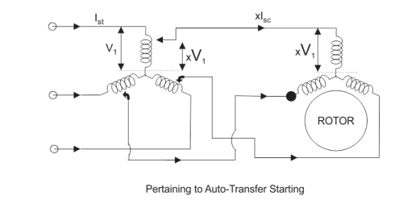
Fig. Stating of autotransformer
2. The autotransformer is a step-down transformer hence it reduces the per phase supply voltage from V1 to xV1. The reduction in voltage reduces current from Is to xIs.
3. After the motor reaches its normal operating speed, the autotransformer is disconnected and then full line voltage is applied.
3. Now let us derive the expression for starting torque in terms of full load torque for the autotransformer starting method. We have various quantities that involved in the expression for the starting torque are written below:
We define Ts as starting torque
Tf as the full load torque
If as per phase rotor current at full load
Is as per phase rotor current at the time of starting
Sf as full load slip
Ss as starting slip
R2 as rotor resistance
Ws as the synchronous speed of the motor
Now we can directly write the expression for the torque of the induction motor as

From the help of the above expression, we write the ratio of starting torque to full load torque as


4. Here we have assumed that the rotor resistance is constant and it does not vary with the frequency of the rotor current. From the above equation, we can have the expression for the starting torque in terms of the full load torque.
5. Now at the time of starting the per phase voltage is reduced to xV1, the per phase starting current is also reduced to xIs. On substituting the value of Is as xIs in equation 1. We have
This shows the variation of the starting torque with the value of x.
3. Star-Delta Starting Method
The connection diagram is shown below for the star-delta method,
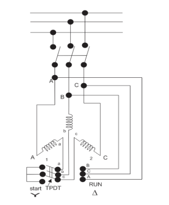
Fig. Star delta connection
1. This method is used for the motors designed to operate in delta connected winding. The terminals are marked for the phases of the stator are shown above. Now let us see this method works.
2.The stator phases are first connected to the star with the help of a triple pole double throw switch (TPDT switch) in the diagram the position is marked as 1 then after this when the steady-state speed is reached the switch is thrown to position 2 as shown in the above diagram.
3. Now, let analyze the working of the above circuit. In the first position, the terminals of the motor are short-circuited and in the second position from the diagram the terminal a, b and c are respectively connected to B, C, and A.
4. Now let us derive the expression for starting torque in terms of full load torque for the star-delta starting method. We have various quantities that involved in the expression for the starting torque are written below
Tf as the full load torque
Ts as starting torque
If as per phase rotor current at full load
Is as per phase rotor current at the time of starting
Sf as full load slip
Ss as starting slip
R2 as rotor resistance
Ws as the synchronous speed of the motor
Now we can directly write the expression for the torque of the induction motor as

From the help of the above expression, we write the ratio of starting torque to full load torque as

5. Here we have assumed that the rotor resistance is constant and it does not vary with the frequency of the rotor current. Let us assume the line voltage to be Vl then the per phase starting current when connected in star position is Iss which is given by

When the stator is in delta connected position we have starting current

From the above equation we have

6. This shows that the reduced voltage method has the advantage of reducing the starting current but the disadvantage is that all these methods of reduced voltage cause the objectionable reduction in the starting torque.
Key takeaways:
1. In DOL the amount of current drawn by the motor depends upon its design and size
2. In the stator resistor starting method Due to the drop in the voltage the starting torque also decreases.
3. In autotransformer starting method. After the motor reaches its normal operating speed, the autotransformer is disconnected and then full line voltage is applied.
4.star delta starting method is used for the motors designed to operate in delta connected winding.
Induction generators are used principally with alternative energy sources such as windmills or wind energy recovery systems for large scale power generation. They are also used to supply additional power to a load in a remote area that is being supplied by a weak transmission line.
Example
A 10 hp, 1760 rpm, 440V, three-phase induction motor operates as an asynchronous generator. The full load current of the motor is 10 A and the full load power factor is 0.8. Determine the required capacitors per phase if capacitors are connected in delta.
Answer-
Apparent power


Active power


Reactive power


For a machine to run as an asynchronous generator, capacitor bank must supply a minimum  VAR per phase
Capacitive current 

Capacitive reactance per phase 
Minimum capacitance per phase


If the load also absorbs reactive power, the capacitor bank must be increased in size to compensate.
Prime mover speed should be used to generate a frequency of 50 Hertz.
CASE STUDY
Driver Circuit for Stepper Motor
Steppers are special motors that do not have any commutator to reverse flow of the windings current. Stepper motors are the best alternatives for applications that high-accuracy motions are required such as CNC, printers and so on. Because of the simple winding and control system, the main applications of these motors are the motion controls. On the basis of the motor structure and operation, stepper motors are divided into three types: permanent magnet (PM), variable reluctance (VR) and hybrids. There is special procedure for driving each of them. In general, stepper motors are driving in full-, half- and micro-step modes. In full-step mode, to change rotor position completely, activation and deactivation signals are fed to the windings alternatively in each cycle.
In half-step, each winding can stay activated for more than on cycle. Therefore, the rotor motion is half of the full-step and the motor resolution is two times more. Micro-step driving is another alternative for motor motion that has more accuracy and continuous motion. Two main advantage of micro-step mode is the possibility for rotor to move between full and half modes and to eliminate irregular characteristics of motor torque. Stepper motor driver circuit implementation process for all three modes is
Presented. For design testing, appropriate driving signal patterns are generated using PC parallel port. Torque tests are applied to the driver circuit and experimental results extracted. As obtained, using micro-step driving, stepper motor rotates more continuously. Also, irregular torque values (appeared like holes in torque curve at resonance frequencies) are eliminated.
Control Circuit
Generally, control and driving techniques for stepper motors are categorized in open- and close-loop modes (here, open-loop mode is considered). In stepper motors, driving is done by activation and deactivation of various windings. In general stepper motor driver circuit is divided into two main parts: signaling and switching [8]. Signaling part is for generating the consequent and regular pulses (patterns) for motor driver. The switching part turns the control switches on and off according to the generated patterns. A four-phase stepper motor driver has two main parts as follows: control signal sequencer and motor driver
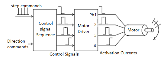
Fig. Driver Circuit
According to the nature of the windings, the current and therefore the switch state could not change suddenly except that infinite opposite voltage is applied to the winding. When the control switch of the winding is closed, the winding current increased gradually. Thus, when its state change (the switch opened), large voltage is applied to the winding. This may damage the control switches if there is no care about it. There are two main strategies to solve these problems: using diode or capacitance in parallel with the
Winding. There are several driving techniques for every type of the stepper motors. Consider a bipolar HBridge hybrid motor, as shown in Fig2. Reversing the magnet field direction, one can change the winding current flow. Achieving this, one can arrange the control switches like H letter (called H-Bridge) and put the winding between them.
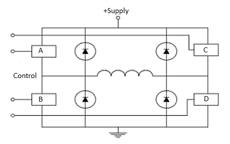
Fig. Bridge Hybrid Model
Because of four control switches, H-Bridge can have 16 different modes of operations. Some of
Them are not used generally. Some of the practical operation modes are as follows
- Forward: only A and D switches are closed.
- Reverse: only B and C switches are closed.
- Fast Decay: All switches are closed and the winding current decreased through the power
- Supply and diodes path. This mode doesn’t damage the winding and therefore the rotor can move freely without any resistance.
- Slow Decay: In this mode, the current is passed through the motor winding rotationally without any resistance. Therefore, if a few current remains in winding, this operation caused the current dissipated and the rotor stopped slowly.
It is possible that activation of control switches in H-Bridges caused short-circuit between power supplies (i.e. closing switches A and B). In these cases, usually logic gates used to eliminate short-circuit effects. Fig 3 shows the sample circuit where this technique is applied.
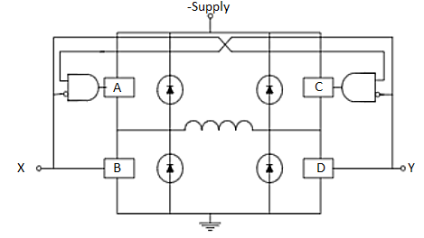
Fig. SC elimination from H bridge
As shown above, all of the operation modes can be accessible only with a few numbers of signals.
This is so practical when we use microcontrollers or microprocessors for control signal (pattern)
Generation (i.e. X and Y signals on the above).
Micro-step driving circuit
In micro-step mode[7], the resolution (number of steps per round) is increased. The motor used pass 1.8 degree per rotation and has resolution equals to 200 steps. After micro-step driving, the target becomes 800 steps per rotation (4 micro-steps per each step). After driver implementation for half- and full-step modes, several parts should be changed and optimized for micro-step driving. One of the main parts is the reference voltage (Vref). Another optimization is to control two phase of the motor independently. For this purpose, driver circuit must be changed to be able to control the winding current independently to the portion of the final phase current. For this, one can control the current of the motor phases to be able to move between two full steps more. According to this, digital to analog converter (DAC) and operational amplifiers (OpAmp) are used to control the reference voltage of the motor. Inputs to the ADC will determined the signal levels and the bit number can perform more accurately. Two L297 devices are used to control the L298 phases separately. These devices should be synchronized by each other. The inhibit output signals of each L297 (INH) control corresponding enable (EN) lines of the L298 (ENA and ENB).
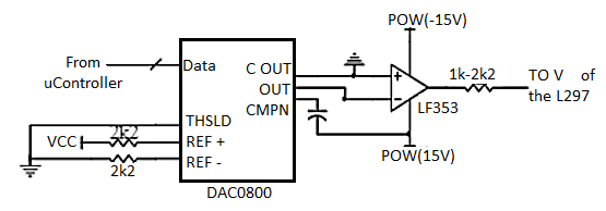
Fig. Micro-step driving circuit
References
1. I. J. Nagrath, D.P. Kothari, “Electrical Machines,”, Tata McGraw- Hill Publishing
Company Ltd.
2. P.S. Bhimbra,”Electrical Machinery”, Khanna Publishers.
3. P.K. Mukherjee, S. Chakrabvorty, “Electrical Machines”, Dhanpat Rai Publications.
4. P.S. Bhimbra, “Generalized Theory in Electrical Machines”, Khanna Publishers.
5. D C Kulshreshtha, “Basic Electrical Engineering,” The McGraw Hill Higher Education Private Limited, New Delhi.