Unit - 5
Single Phase Machines
A Single- Phase Induction Motor consists of a single- phase winding which is mounted on the stator of the motor and a cage winding placed on the rotor. A pulsating magnetic field is produced, when the stator winding of the single-phase induction motor shown below is energised by a single- phase supply.
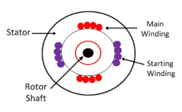
The word Pulsating means that the field builds up in one direction falls to zero and then builds up in the opposite direction. Under these conditions, the rotor of an induction motor does not rotate. Hence, a single -phase induction motor is not self-starting. It requires some special starting means.
If the 1 phase stator winding is excited and the rotor of the motor is rotated by an auxiliary means and the starting device is then removed, the motor continues to rotate in the direction in which it is started.
The performance of the single- phase induction motor is analysed by the two theories. One is known as the Double Revolving Field Theory, and the other is Cross Field Theory.
The double revolving field theory of single- phase induction motor states that a pulsating magnetic field is resolved into two rotating magnetic fields. They are equal in magnitude but opposite in directions. The induction motor responds to each of the magnetic fields separately. The net torque in the motor is equal to the sum of the torque due to each of the two magnetic fields.
The equation for an alternating magnetic field is given as

Where βmax is the maximum value of the sinusoidally distributed air gap flux density produced by a properly distributed stator winding carrying an alternating current of the frequency ω, and α is the space displacement angle measured from the axis of the stator winding.
So, the equation (1) can be written as

The first term of the right-hand side of the equation (2) represents the revolving field moving in the positive α direction. It is known as a Forward Rotating field. Similarly, the second term shows the revolving field moving in the negative α direction and is known as the Backward Rotating field.
The direction in which the single- phase motor is started initially is known as the positive direction. Both the revolving field rotates at the synchronous speed.
ωs = 2πf in the opposite direction.
Thus, the pulsating magnetic field is resolved into two rotating magnetic fields. Both are equal in magnitude and opposite in direction but at the same frequency.
At the standstill condition, the induced voltages are equal and opposite as a result; the two torques are also equal and opposite. Thus, the net torque is zero and, therefore, a single- phase induction motor has no starting torque.
Methods for Making Single Phase Induction as Self- Starting Motor
The single-phase induction motors are not self-starting because the produced stator flux is alternating in nature and at the starting, the two components of this flux cancel each other and hence there is no net torque. The solution to this problem is that if we make the stator flux rotating type, rather than alternating type, which rotates in one particular direction ,then the induction motor will become self-starting.
Now for producing this rotating magnetic field, we require two alternating flux, having some phase difference angle between them. When these two fluxes interact with each other, they will produce a resultant flux. This resultant flux is rotating in nature and rotates in space in one particular direction only.
Once the motor starts running, we can remove the additional flux. The motor will continue to run under the influence of the main flux only. Depending upon the methods for making asynchronous motor as Self-Starting Motor, there are mainly four types of single -phase induction motor namely,
- Split phase induction motor,
- Capacitor start inductor motor,
- Capacitor start capacitor run induction motor,
- Shaded pole induction motor.
- Permanent split capacitor motor or single value capacitor motor.
The double-revolving field theory of single-phase induction motors states that a stationary pulsating magnetic field can be resolved into two rotating magnetic fields, each of equal magnitude but rotating in opposite directions. The induction motor response to each magnetic field separately and the net torque in the motor is equal to the sum of the torques due to each of the two magnetic fields.
The equation for an alternating magnetic field whose axis is fixed in space is given by

Where 𝛃max is the maximum value of the sinusoidally distributed air-gap flux density produced by a properly distributed stator winding carrying an alternating current of frequency ω and α is space displacement angle measured from the axis of the stator winding.


The first term on the RHS represents the equation of a revolving field moving in the positive 𝛂 direction. It has a maximum value equal to 
The second term on the RHS represents the equation of revolving field moving in negative α direction. It has a maximum value equal to 
The field moving in the positive α direction is called the forward rotating field. The field moving in the negative 𝛂 direction is called a backward rotating field.
The positive direction is the direction in which the single-phase motor is started initially.
When the rotor is stationary, the induced voltages are equal and opposite consequently two torques are also equal and opposite. Hence, at standstill, the net torque is zero. In other words, a single-phase induction motor with a single stator winding inherently has no starting torque.
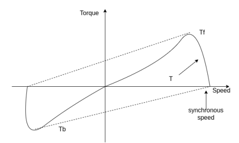
Fig. Torque-Speed Characteristics
Key takeaway
The double-revolving field theory of single-phase induction motors states that a stationary pulsating magnetic field can be resolved into two rotating magnetic fields, each of equal magnitude but rotating in opposite directions.
Split phase Induction Motor:
In this type of motor an auxiliary winding is connected in addition to the main winding. There is one switch called centrifugal switch (S) which disconnects the auxiliary winding from the main winding. If the starting winding has high resistance than only a phase difference can be created between these windings. The main purpose of creating this phase difference is to get the magnetic field rotated because IM cannot self start.
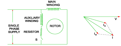
Fig: Split phase IM
For highly resistive winding the current is almost in phase with the voltage and for highly inductive winding the current lag behind the voltage by large angle. The starting winding is highly resistive so, the current flowing in the starting winding lags behind the applied voltage by very small angle and the running winding is highly inductive in nature so, the current flowing in running winding lags behind applied voltage by large angle. The resultant of these two currents is IT. The resultant of these two currents produce rotating magnetic field which rotates in one direction. In split phase induction motor, the starting and main current get splitted from each other by some angle so this motor got its name as split phase induction motor.
Shaded pole:
This motor works I three operating regions. The poles of the motor are shaded by copper ring which are inductive. They are divided in two equal halves. The operation of such motor takes place at different flux changes:
i) When flux change from zero to positive maximum the copper band is short circuited and maximum current flows through it. This current produces its own flux. This flux opposes the main flux. So, in non-shaded part there is non uniform distribution of flux casing the magnetic axis to shift in middle of the non-shaded part.
Ii) When flux is still at its maximum and very less induced emf in the shaded portion. The main flux is not affected by the induced emf and hence, uniform flux remains.
Iii) The flux the decreases from maximum positive to zero, the current is high. The copper band is short circuited and maximum current flows through it. This current produces its own flux. This flux opposes the main flux. So, in shaded part there is non uniform distribution of flux casing the magnetic axis to shift in middle of the shaded part.
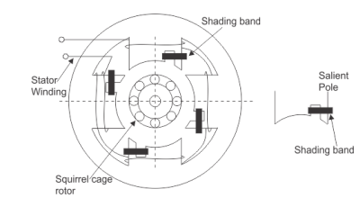
Fig: Shaded Pole Induction Motor
Capacitor start IM and Capacitor start capacitor run IM: These two motors have same working so discussing them together. In induction motor there is no rotating flux so the motor cannot be self-started. So, a phase difference is being produced to get the rotating magnetic field. A capacitor is used to create a phase difference in this case.
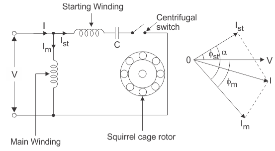
As the figure above shows we have main winding and starting winding. The capacitor is connected with the starting winding. The current Ist through the capacitor leads the voltage by some angle. The large phase difference between main winding current and starting winding current produces a resultant current I. This I generate rotating magnetic field.
These motors produce very high starting torque. In capacitor start induction motor, the centrifugal switch is provided so as to disconnect the starting winding when the motor attains a speed up to 75 to 80% of the synchronous speed but in case of capacitor start capacitors run induction motor there is no centrifugal switch so, capacitor remains in the circuit and helps to improve the power factor and the running conditions of single phase induction motor.
1. The Split Phase Motor is also known as a Resistance Start Motor. It has a single cage rotor, and its stator has two windings known as main winding and starting winding.
2. Both the windings are displaced 90 degrees in space. The main winding has very low resistance and a high inductive reactance whereas the starting winding has high resistance and low inductive reactance.
3. Split-Phase-Induction-Motor-resistor is connected in series with the auxiliary winding. The current in the two windings is not equal as a result the rotating field is not uniform.
4. Hence, the starting torque is small, of the order of 1.5 to 2 times of the starting running torque. At the starting of the motor both the windings are connected in parallel.
5. As soon as the motor reaches the speed of about 70 to 80 % of the synchronous speed the starting winding is disconnected automatically from the supply mains.
6. If the motors are rated about 100 Watt or more, a centrifugal switch is used to disconnect the starting winding and for the smaller rating motors relay is used for the disconnecting of the winding.
7. A relay is connected in series with the main winding. In the starting, the heavy current flows in the circuit, and the contact of the relay gets closed.
8. Thus, the starting winding is in the circuit, and as the motor attains the predetermined speed, the current in the relay starts decreasing. Therefore, the relay opens and disconnects the auxiliary winding from the supply, making the motor runs on the main winding only.
The phasor diagram of the Split Phase Induction Motor is shown below.
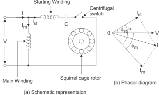
Fig. Schematic diagram and phasor diagram of split-phase induction motor
9. Split-Phase-Induction-Motor-The current in the main winding (IM) lag behind the supply voltage V almost by the 90-degree angle. The current in the auxiliary winding IA is approximately in phase with the line voltage.
10. Thus, there exists a time difference between the currents of the two windings. The time phase difference ϕ is not 90 degrees, but of the order of 30 degrees. This phase difference is enough to produce a rotating magnetic field.
Applications of Split Phase Induction Motor
This type of motors are cheap and are suitable for easily starting loads where the frequency of starting is limited. This type of motor is not used for drives that require more than 1 KW because of the low starting torque. The various applications are as follows:
1. Used in the washing machine, and air conditioning fans.
2. The motors are used in mixer grinder, floor polishers.
3. Blowers, Centrifugal pumps
4. Drilling and lathe machine.
Key takeaways:
1. As soon as the motor reaches the speed of about 70 to 80 % of the synchronous speed the starting winding is disconnected automatically from the supply mains.
2. This type of motor is not used for drives that require more than 1 KW because of the low starting torque
These are used in low power applications and widely used in domestic applications as well as industrial. And some of those are mentioned below
- Pumps
- Compressors
- Small fans
- Mixers
- Toys
- High speed vacuum cleaners
- Electric shavers
- Drilling machines
A series motor designed for operation on DC does not show good performance when operated on AC.
Small fractional bp what is known as universal motors are widely used for food mixers, vacuum cleaners, hair dryers, electric shavers, portable drills, sewing machines etc.
They are ac series motors generally without compensating winding and can be used on both AC and DC.
They have ratings: below 0.75 HP and have high operating speed of around 7000 rpm or so.
The high speed results in a small weight and size of the motor. The friction and windage losses are sufficient to limit the no load speed to a safe value.
Armature current is small, so that serious commutation problems are eliminated.
Phasor diagram-
In a universal motor the q axis field created by armature current is also present in addition to the Direct axis field ϕd created by the series field winding.
In an AC series motor with compensating winding the q axis field is neutralized by the effect of compensating winding.
Both these fields alternate at supply frequency. Each of these field sets up rotational EMF and transformer EMF.
The d axis flux ϕd creates a rotational EMF across the brushes.
In a DC machine this EMF E is
E = 
Where ϕ =Flux per pole
Z=number of armature conductors
P=number of poles
A=number of parallel paths
n= speed, revolutions/second
The frequency corresponding to speed n is 
Therefore,
E = 2 
If flux ϕ is alternating i.e., ϕ= ϕd sin ωt, the instantaneous value of rotational EMF er is

And the rms value Er is

This EMF is in phase with flux 
Since flux is alternating flux, transformer EMF is also induced in armature coils. This EMF adds to zero at the brushes.
The q axis flux  (created by armature coils) also sets up rotational and transformer EMFs. The transformer EMF due to this flux
  Is
Is

Where
 =RMS value of transformer EMF, volts.
f=supply frequency
 =breadth factor (since the armature winding is distributed in slots)
If 

Since  is alternating at the supply frequency f, it induces a transformer EMF in the field winding which is a concentrated winding of Nf turns. This EMF is given by

This EMF is in quadrature with flux  therefore,
  and
and  are in phase. Both these EMF are proportional to and in quadrature with current I. Therefore, it is possible to write
  , where X is a constant of proportionality and has the dimensions of reactance.
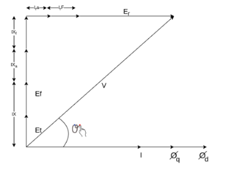
Fig. Phasor Diagram of Universal Motor
Example
A 2 pole, 50 HZ, 230-volt universal motor has 1200 armature turns and 400 series field turns. When operated on AC, the full load current is 1 A, field flux is 0.0008 weber and speed is 7000 rpm. The total resistance and leakage reactance are 20 ohm and 30 ohm respectively. Find
a) Transformer EMF induced in the armature winding by the quadrature flux
b) Quadrature flux
c) HP output
d) Speed of operation if machine is connected to DC supply and takes 1 A. The armature is wave wound.
Solution->
a) 
A=2, Z=1200*2, 


=158.37V

= √2 π (50) (400)(0.0008)
=71V
The phasor diagram is shown below
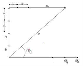


Et = 44.2 V
b) 
44.2 = 2 × √2 (50) 

c) 

=0.814
Cos θ = 0.776 lagging
Power input= V I Cos θ
= 230 × 1 × 0.776
= 178.48 watt
Copper losses = l2(ra+rf)
= 20 watt
Neglecting other losses=power output=178.48-20
=158.48 watt

When connected to DC supply
Vdc = 230 Vr Idc = 1 A
Ebdc = 230 – Idc (ra + rf)
=230-20
=210V


=9282 rpm
4. The motor of above example is provided with a compensating winding having a resistance of 2 ohm and reactance of 5 ohm. The compensating winding neutralizes armature flux completely. Find the speeds of operation on AC and DC if V=230V and I=1A
Since ϕq has been neutralized fully
Et = 0,Xc = 5Ω,rc = 2Ω
V2 = 
2302 = (71 + 1(30 + 5))2 + [ Er + 1 (20 + 2)]2
Er = 182.12 V
If Nac is the new speed for AC operation

Nac = 8050 rpm
When connected to DC supply
Erdc = Vdc – Idc (ra + rf + rc)
=230 – 1(20 +2 )
=208

Ndc = 9194 rpm
5. A universal series motor has a resistance of 30 and an inductance of 0.5 H. When connected to a 250 V dc supply and loaded to take 0.8 A it runs at 2000 rpm. Determine the speed, torque and power factor, when connected to a 250 V, 50 Hz ac supply and loaded to take the same current.
Operation of motor on dc
Ebdc = V-IaRa = 250-0.8 x 30 = 226V
Ndc = 2000rpm
Operation motor on ac
XL = 2πfL = 2πx 50x0.5=157 𝛀
From phasor below we get
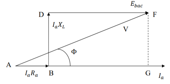
AF2 = AG2 + GF2
V2 = (AB + BG)2 + GF2 = (AB + DF)2 + GF2
= (Ia Ra + Ebac)2 + (IaXl)2
Ebac = - 0.8 × 30 + 
= - 24 + 216.12 = 192.12 V
Since the currents in dc and ac operation are equal, the flux will also be equal ɸac= ɸdc


Power factor cos ϕ =  (lagging)
Mechanical power developed
Pmech = Ebac Ia = 192.12 × 0.8 = 153.7 W
Torque developed
τ = 
A Hysteresis Motor is a synchronous motor with a uniform air gap and without DC excitation. It operates both in single and three phase supply.
The Torque in a Hysteresis Motor is produced due to hysteresis and eddy current induced in the rotor by the action of the rotating flux of the stator windings.
The working of the motor depends on the working of the continuously revolving magnetic flux. For the split phase operation, the stator winding of the motor has two single phase supply. This stator winding remains continuously connected to the single phase supply both at the starting as well as the running of the motor.
The rotor of the motor is made up of smooth chrome steel cylinder and it has no winding. It has high retentivity and because of this, it is very difficult to change the magnetic polarities once they are caused by the revolving flux of the rotor. The rotor of the hysteresis motor moves synchronously because the pole of the motor magnetically locks with the stator which has opposite polarities.
Construction of Stator of Hysteresis Motor
The stator of the hysteresis motor produces a rotating magnetic field and is almost similar to the stator of the induction motor. Thus, the stator of the motor is connected either to single supply or to the three phase supply.
The stator winding of the single-phase hysteresis motor is made of permanent split capacitor type or shaded pole type. The capacitor is used with an auxiliary winding in order to produce a uniform field.
Construction of Rotor of Hysteresis Motor
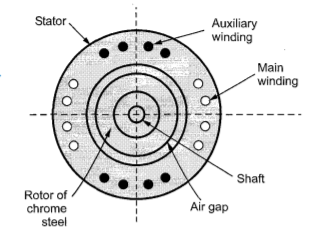
The rotor of the hysteresis motor consists of the core of aluminium or some other non-magnetic material which carries a layer of special magnetic material. The figure shows the rotor of the hysteresis motor.
The outer layer has a number of thin rings forming a laminated rotor. The rotor of the motor is a smooth cylinder, and it does not carry any windings. The ring is made of hard chrome or cobalt steel having a large hysteresis loop as shown in the figure below.
Operation of a Hysteresis Motor
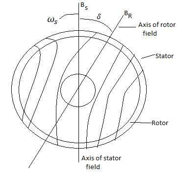
When supply is given applied to the stator, a rotating magnetic field is produced. This magnetic field magnetises the rotor ring and induces pole within it.
Due to the hysteresis loss in the rotor, the induced rotor flux lags behind the rotating stator flux.
The angle δ between the stator magnetic field BS and the rotor magnetic field BR is responsible for the production of the torque. The angle δ depends on the shape of the hysteresis loop and not on the frequency.
Thus, the value of Coercive force and residual flux density of the magnetic material should be large.
The ideal material would have a rectangular hysteresis loop as shown by loop 1 in the hysteresis loop figure. The stator magnetic field produces Eddy currents in the rotor. As a result, they produce their own magnetic field.
The eddy current loss is given by the equation,
Pe = Kef2s2 B2
Where, ke is Eddy current constant
f2 is the eddy current frequency
B is the flux density
The relation between rotor frequency f2 and supply frequency f1 is f2 = sf1 where s is the slip.
Therefore, Pe = Ke s2 f12 B2
The torque due to eddy current is Te = Pe/swsor Te = K’s
K’= Kef12B2/ws
The hysteresis loss is Ph = Khf2B1.6 or Kh sf1B1.6
The Torque due to hysteresis is Th = Ph/sws= k’’
K’’ = Khf1B1.6/ws
From the equation it is clear that the torque is proportional to the slip. Therefore, as the speed of the rotor increases the value of Ʈe decreases.
As the speed of the motor reaches synchronous speed, the slip becomes zero and torque also becomes zero.
As the electromagnet torque is developed by the motor is because of the hysteresis loss and remains constant at all rotor speed until the breakdown torque.
At the synchronous speed, the eddy current torque is zero and only torque due to hysteresis loss is present.
Torque Speed characteristic of Hysteresis Motor
The speed torque curve of the motor is shown below.
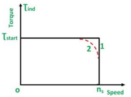
Curve 1 is the ideal curve, and the curve 2 is the practical hysteresis motor curve.
The torque-speed characteristic of the hysteresis motor is different from an induction motor.
Since, at the synchronous speed, the torque developed by an induction motor becomes zero, whereas in the hysteresis motor the torque is constant at all the speed even at the synchronous speed.
Thus, from the curve, it is seen that the locked rotor, starting and pull out torque is equal.
The noise level of the hysteresis motor is very low as compared to the induction motor because it operates at a constant speed and its rotor is smooth.
This type of motor is smoothest running, quietest single phase motor and is used for quality sound reproduction equipment like record players, tape recorders, etc. It is also employed in electric clocks and other timing devices.
The term “DC motor” is traditionally used to refer to “brushed DC motors”. In DC motors section, we have seen that brushes are required to convert alternating current generated in DC generators to direct current (and vice versa for DC motors). We have also seen that a “field winding” is used to produce the magnetic field required for energy conversion. If the winding is replaced by permanent magnets, the rotating magnetic field is then generated without the need of separate winding. Besides, the losses in the field will be eliminated. There has been a significant improvement in permanent magnet technology since last few years. The permanent magnets are alloys like Neodymium Iron Boron (NdFeB) and Samarium Cobalt have become popular in recent years. Now, if permanent magnets are placed on rotor, the armature winding will be stationary and hence brushes can be removed. This has two advantages - 1. Resistive losses in brushes are completely eliminated 2. Maintenance and safety issues are also taken care of. Thus, the DC motor with permanent magnets without brushes is called brushless DC motor or simply BLDC motor.
The operating principle of BLDC motor is same as that of the DC motor. Conductors facing a particular magnet pole (say N pole) carry current in one direction while those facing the other pole carry current in opposite direction. By virtue of this, the fields created by magnet and armature conductors are always orthogonal to each other as shown in the Figure. Note the naming convention “direct axis” and “quadrature axis”. N S direct axis quadrature axis armature coils field coil
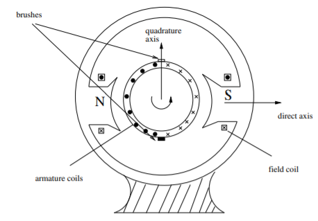
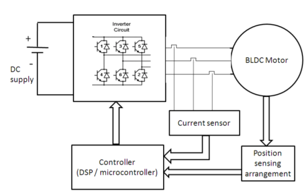
Suppose a two pole rotor is rotating under an armature. When N pole passes completely across a conductor, some mechanism is necessary to change the direction of current in that conductor. Otherwise, direction of force on the conductor will be reversed. In a conventional DC motor, the number of commutator segments equals the number of conductors in the armature. When a commutator segment switches from one brush to the other, there is a change in supply direction (in case of motor). In BLDC machine, this reversal of direction of current is done via power electronic switches. Now, the instant of reversing the direction is a function of position of rotor. Hence, sensing of position is required which is “feedback” to the power electronics drive which “drives and controls” the supply given to the motor. Hence complete block diagram of a BLDC drive is as shown in Figure. It consists of 3 parts
- BLDC machine
- Power electronics (DC-AC converter)
- Position sensing and drive control system
AC series motor are also known as the modified DC series motor as their construction is very similar to that of the DC series motor.
What will happen when we give an AC supply to DC series motor?
1) An AC supply will produce a unidirectional torque because the direction of both the currents (i.e. armature current and field current reverses) at the same time.
2) Due to presence of alternating current, Eddy currents are induced in the yoke and field course which result in excessive heating of the yoke and field cores.
3) Due to the inductance of the field and the armature circuit, the power factor would become very low.
4) There is sparking at the brushes of the DC series motor.
Thus, considering above points we can say that we don't have good performance of DC series motor on the application of AC supply. There need some modifications
a) In order to reduce the Eddy currents there is need to laminate the yoke and field core.
b) The power factor is directly related to reactance of the field and armature circuit and we can reduce the field winding reactance by reducing the number of turns in the field winding. But on reducing the number of turns, field MMF will decrease and due to this the air gap flux will decrease. The overall result of this is that there is an increase in the speed of the motor but decrease in the motor torque which is not desired.


The solution to this problem is the use of compensating winding.
c) The number of armature conductors is increased in order to get the required torque with the low flux.
Key takeaway
There are eddy current losses and lamination is required to reduce them. The torque developed is given as

Examples
Q1) Determine torque established by the armature of six pole DC motor having 680 conductors, two paths in parallel, 24mWb flux/pole and armature current 50A?
Sol: 
T= x24x10-3x50x680x (4/2) =259.74 N-m
Q2) A 220V DC Shunt motor runs at 450rpm when armature current is 39A. Calculate speed if the torque is doubled. The armature has a resistance of 0.2 ohm?
Sol: Ta αφIa
Ta1 αφIa1 and Ta2 αφIa2
2= Ia2/39
Ia2=78A
N2/N1=Eb2/Eb1
Eb1=220-(39x0.2) =212.2Volts
Eb2=220-(78x0.2) =204.4Volts
N2/450=204.4/212.2
N2=433.46 rpm
Q.3 A 4 pole, 210 V shunt motor has 450 lap wound conductor. It takes 32 A from supply mains and develops output power of 4.5 kW. The field takes 1 A. The armature resistance is 0.09 ohm and flux per pole is 30 mWb. Calculate speed and torque.
Soln. Ia = 32-1 = 31 n
Eb = V – Ia Ra = 210 - (0.09×31) = 207.21 V


N = 920.9 rpm


Q.4 A 220 V, dc shunt motor has an armature resistance of 0.3 ohm and field resistance of 105 ohm. At no load speed is 1200 rpm and armature current is 2.3 A on application of rated load speed drops to 1120 rpm. Find the current and power input when motor delivers rated load.
Soln. N1 = 1200 rpm Eb1 = 220 – (0.3×2.3) = 219.31 V
N2 = 1120 rpm Eb2 = 220 – 0.3 Ia2


Ia2 = 37.93 A
Line current = Ia2 + Ish = 37.93 + (220/105) = 40 A
Power input = 220 × 40 = 8800 W
Q.5 A 230 V shunt motor runs at 1000 rpm at no load and takes 6A. The total armature resistance is 0.2 ohm and field resistance is 210 ohms. Calculate the speed when loaded and taking 40 A. Assume flux constant.
Soln. 


Q.6 The armature resistance of a 15 kW, 230 V series motor is 0? 1 ohm, the brush voltage drop is 3 V and series field resistance is 0.05 ohm. The motor takes 60 A speed is 600 rpm. Calculate speed when current is 100 A.
Soln.


Φ1 60
60
Φ2 100
100


N2=350.22 rpm
Q.7 A 230V DC Shunt motor takes 4A at no load when running at 600 rpm. The field resistance is 100 ohms. The resistance of armature at standstill gives a drop of 6V across armature terminals when 10A were passed through it. Find i) Speed at no load (ii) Torque. Normal input of motor is 6kW
Sol:
i)Speed 
Ish=  =2.3A
=2.3A
F.L Power=6000
F.L line current=  =26.08A
Ia=26.08-2.3=23.78A
Ra= =0.6Ω
=0.6Ω


N=566.2 rpm
Ii)Torque
 =
=

References
1. I. J. Nagrath, D.P. Kothari, “Electrical Machines,”, Tata McGraw- Hill Publishing
Company Ltd.
2. P.S. Bhimbra, “Electrical Machinery”, Khanna Publishers.
3. P.K. Mukherjee, S. Chakrabvorty, “Electrical Machines”, Dhanpat Rai Publications.
4. P.S. Bhimbra, “Generalized Theory in Electrical Machines”, Khanna Publishers.
5. D C Kulshreshtha, “Basic Electrical Engineering,” The McGraw Hill Higher Education Private Limited, New Delhi.